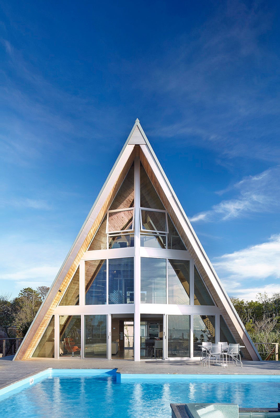
It is shaped like a kite...
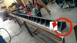
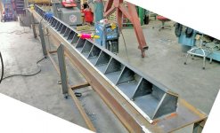
Never in my life have I seen a "Heater Vent" made from 5/8 plate with 3/8 thick KITE shaped formers... you seriously can't see that it is shaped like a kite in cross section? in the earlier pics there are only 3 of the 4 sides shown tacked in place, each KITE shaped former is full welded in place, and the outer plates are full welded inside EXCEPT the last plate the formers are 8" apart, there just ain't no way to get a little guy in there to weld the last plate on...
the wider plates are 7" the narrower are 4 5/16, the wider plates had to be beveled with a track torch on one edge. then all the seams had to be stitch welded (Skip Welded) in 4" segments it still curved up we shrunk it with a rosebud in a couple spots, we cut it and laid it out in a couple spots, all of the seams had to be filled and high so they could be ground back down and profiled, at one point there were 3 of us skip welding 3 different seams trying to avoid being right next to each other, then letting it cool completely then stitching it some more. the Baseplate is 3/4" Plate cut on the plasma table to shape. it is a vertical structural post that separates the glazing on the front of a house. since there is no real support on that wall except the side posts and this post, we were the second attempt at this another shop tried it and couldn't get it straight. I just finished welding the last seam and filling in gaps and grinding the last seam this morning. Then sprayed it with Red oxide primer


![Beam%203_zpsn2rs20ur[1].jpg](/forum/data/attachments/570/570770-504ddc88cd3e8d3bceb74bc0382f1cad.jpg)


![IMG_20170206_193720111[1].jpg](/forum/data/attachments/546/546346-3510cd6b54587bfcadd1122ba11ae688.jpg)
![IMG_20170206_193705915[1].jpg](/forum/data/attachments/546/546293-2618bbdc1b7cf0969caf6948b010c9e2.jpg)
![IMG_20170206_193544053[1].jpg](/forum/data/attachments/546/546252-ba2a8fa6208db28da723b727349ba1a8.jpg)


