To avoid these ads, REGISTER NOW!

Show us your welding projects

TimeWarpF100

Well-known member
Joined
Aug 21, 2010
Messages
6,784
Location
not here
Here is what I started with. 300.00 truck ready for scraper. Bought a new frame from ford in closest WB possible. Stock 129" WB frame was 126" WB. Hard part was trying to get computers to work on the 126" wb when donor was for 145" wb.

I installed the full firewall (quiet steel) floor and full dash from the F150
DSC00156.JPGDSC00157.JPG
 
To avoid these ads, REGISTER NOW!

TimeWarpF100

Well-known member
Joined
Aug 21, 2010
Messages
6,784
Location
not here
To accommodate the 6" wider frame I modified the cab in this way to make it appear stock.
Shortening the frame or extending the bed?
Stock '66 WB was 129" the frame was for 126" wb. I moved the cab forward on chassis 1" and removed 2" from bed to make it fit.
Original donor truck had a 145" wb so used that PCM.
Never know where bed was shortened. ALso grafted in the fuel door and capless filler. All metal finished no bondo
13329343_265382483816446_4068679825644342291_o.jpg
 

sanddan

Well-known member
Joined
Jul 7, 2005
Messages
708
Location
Oregon
I bought this old 10"x36" bench top lathe many months ago and it came with a chintzy homemade angle iron stand that a despised. So I threw the old one in the scrap pile and made a new one with built in tool storage had paint mixed up to match the 1980 Taiwanese lathe. I'm also going to fabricate up a rear splash guard sometime over Christmas.
Here’s the one did for my PM1340 lathe. Tool box is from HF.E24A7D82-BDA3-43CD-82A4-408EA5DDD60D.jpeg
 

metal1313

Well-known member
Joined
Apr 28, 2009
Messages
3,416
Location
clinton NJ
Flopping around when? You can pull a pin and remove the entire jack when it's not in use lifting the mower. Only the stub piece that it slides onto is permanently mounted to the mower.
i totally didnt notice the pin at all, I like it, and if i has a z-turn i would def do the same. now i'm trying to figure out how to make something similar work on my little lawn tractor, i refuse to pay hundreds for a mower lift to use 2-3 times a year that will otherwise just sit around and take up room
 

TimeWarpF100

Well-known member
Joined
Aug 21, 2010
Messages
6,784
Location
not here
I just finished a rotisserie for use in 1965-66 Ford truck restoration mostly.
Cabs, boxes, full chassis’s. Many multi use.

Some key features i wanted. Started from a very basic base sketch then added on, made changes once i got going. Taking a few cab/box measurements i knew i needed a 44” swing.
Because i couldn’t buy remnants of proper pipe sizes i had to make like a bushing for more precise fit. It was during making these pieces i had a brainstorm to add a brake vs drilling holes for multiple positions. *(Don't have a lathe or mill just a 35.00 drill press from 40yrs ago used and basic hand tools)

And, the hidden brake system works fantastic! Something i have not seen done.

Old age kicking in and simply not able to crawl under a cab out back under multiple times needed figured to make attempt to build my own. Most of it afterthoughts like hidden brakes and the area around wheels to keep height low.
The 6 8” tall steel wheels good for 1050lb ea are really nice for pushing in dirt.
I was quite surprised how perfect it pushes all by pure luck 🍀. Work alone 90+ % of time.
I also added in a adjustable length arm in middle. A full 1’ plus between rotis and cab both ends to allow full body work and final paint. 5FE4B4CE-0DB8-452B-BF29-7940037EEF6A.jpeg86211286-D6C4-4980-9F28-263F6B1FA893.jpeg8A1A1EEA-40FB-40F4-B7A2-B206FD61E838.jpeg7F1ECB7D-66D0-428E-B849-196CED058386.jpeg30C0B926-016C-47EC-A349-D103EE4704B7.jpeg
 

Old Man Roger

Well-known member
Joined
Apr 6, 2017
Messages
17,427
Location
Palm Coast Florida
Here is a short vid of it in operation. Total beginner so do not post here often. Not to mention 180 deg from a engineer. I gotta do it like a puzzle. Throw in some metal basic stuff and see what I can put together.

At first I didn’t see anyone standing back there, I thought you had some kind of remote control.lol
 

TimeWarpF100

Well-known member
Joined
Aug 21, 2010
Messages
6,784
Location
not here
^^Nice work on the rotisserie! How does the hidden brake work? I was looking for it in the photos, but apparently it is too well hidden.
Thanks! Well hidden ha! I will post more pics. There are actually 4 brakes. During testing 1 brake with 10 ft lb tq would give 100 lb rotating resistance so total adjustable. I had no idea how it would balance just guessed where the weight would be and to keep it within the 44" radius. At no time during rotation will it go far on it's own if I let go no brake applied.
Have had quite a few say I should patent it but the patent office said they do NOT take food stamps, so I guess that is out . .
Fancy caster cutouts too. 👍
I wanted it to have decent look but yet keep it simple and low for ease of use with the tall 8" steel casters.

Will post more detail in a bit.
 

IRQVET

Well-known member
Joined
Jun 29, 2015
Messages
1,188
Location
Forgotten Coast (FL)
I had to replace alot of sheet metal on my 49 Willys after bubba the bondo bandit got his hands on it. Dude made an entire cab corner out of bondo. (WTF does that!?) So I stripped this thing down to bare metal, and I cut out all rust and bondo and replaced with with new sheet metal. Now its a bondo free rig.

Jeep Sitting.JPG

Hobart Jeep.jpg

Shark Bite.jpgShark bit fixed.jpg
 
Last edited:

ekuhn

Well-known member
Joined
Jun 7, 2010
Messages
223
Location
08873
Working on a little side project. I welded up this 2 1/2” x 1/4” tube to this 1/4” plate. The plate warped slightly. This was a trial run, so I just used the flux core wire I had in my welder. Will make welds prettier next time. I did a small stitch on each side to hold it in place and square, then welded each face.

Question is how can I prevent the 1/4” plate from warping? Clamp closer to the tube?

AC9B1F87-7DA6-4052-8ADC-C9E4B0B0D736.jpeg

62C76205-D63A-4D37-A6AE-246C38D1B11C.jpeg
 

f150skidoo

Well-known member
Joined
Dec 29, 2012
Messages
1,206
Location
Ontario, Canada
I built this toe jack out of material I had kicking around. The bottle jack originally had a clevis mount that had a thrust bearing so the jack could rotate. I machined a matching pocket so I can rotate the jack around to multiple positions to operate the toe jack. The bottom plate is 5/8" with the fixed mast being 2" 1/4" wall square tube, the moving part is truck receiver tube with the toe and top cylinder mounts made from 3/8" plate. Tomorrow I'm going to put it to the test by lifting my 2200 lb milling machine up so I can put levelling feet under it
 

Attachments

  • IMG_1446.jpg
    IMG_1446.jpg
    987.8 KB · Views: 116
  • IMG_1447.jpg
    IMG_1447.jpg
    785.4 KB · Views: 116
  • IMG_1448.jpg
    IMG_1448.jpg
    831.6 KB · Views: 122
  • IMG_1450.jpg
    IMG_1450.jpg
    950.9 KB · Views: 121

f150skidoo

Well-known member
Joined
Dec 29, 2012
Messages
1,206
Location
Ontario, Canada
Working on a little side project. I welded up this 2 1/2” x 1/4” tube to this 1/4” plate. The plate warped slightly. This was a trial run, so I just used the flux core wire I had in my welder. Will make welds prettier next time. I did a small stitch on each side to hold it in place and square, then welded each face.

Question is how can I prevent the 1/4” plate from warping? Clamp closer to the tube?

AC9B1F87-7DA6-4052-8ADC-C9E4B0B0D736.jpeg

62C76205-D63A-4D37-A6AE-246C38D1B11C.jpeg
Clamping to a table will help but no matter what you do there will always be some distortion.
 

TimeWarpF100

Well-known member
Joined
Aug 21, 2010
Messages
6,784
Location
not here
^^Nice work on the rotisserie! How does the hidden brake work? I was looking for it in the photos, but apparently it is too well hidden.
Sshhh, don’t tell anyone.
There are 4 of them. There was zero thought for a brake but because of availability on pipe/tubing sizes there was too much slop. Thickness issue etc so started to make bushing/sleeves then idea hit me worth a attempt to see what happens.

see post 7681 here:


0A3397F5-7E93-4641-A2E7-94FDFF00AF3E.jpeg
 

welder4956

Well-known member
Joined
Apr 8, 2010
Messages
3,059
Location
Birmingham, AL USA
Sshhh, don’t tell anyone.
There are 4 of them. There was zero thought for a brake but because of availability on pipe/tubing sizes there was too much slop. Thickness issue etc so started to make bushing/sleeves then idea hit me worth a attempt to see what happens.

see post 7681 here:


0A3397F5-7E93-4641-A2E7-94FDFF00AF3E.jpeg
Simple but genius. I like it. The bolt tightens against the segment piece that is sandwiched in the middle.
 
To avoid these ads, REGISTER NOW!

sanddan

Well-known member
Joined
Jul 7, 2005
Messages
708
Location
Oregon
Working on a little side project. I welded up this 2 1/2” x 1/4” tube to this 1/4” plate. The plate warped slightly. This was a trial run, so I just used the flux core wire I had in my welder. Will make welds prettier next time. I did a small stitch on each side to hold it in place and square, then welded each face.

Question is how can I prevent the 1/4” plate from warping? Clamp closer to the tube?

AC9B1F87-7DA6-4052-8ADC-C9E4B0B0D736.jpeg

62C76205-D63A-4D37-A6AE-246C38D1B11C.jpeg
Less weld. Or short weld then let cool before next bead. Rinse and repeat. It’s the heat concentrated in the center of the thin plate that causes it to warp. Clamping closer to welds and leaving them on until it totally cools might help. Pretty common.
 

iagsxr

Well-known member
Joined
Jan 10, 2010
Messages
1,499
Location
Vinton, Iowa
Working on a little side project. I welded up this 2 1/2” x 1/4” tube to this 1/4” plate. The plate warped slightly. This was a trial run, so I just used the flux core wire I had in my welder. Will make welds prettier next time. I did a small stitch on each side to hold it in place and square, then welded each face.

Question is how can I prevent the 1/4” plate from warping? Clamp closer to the tube?

AC9B1F87-7DA6-4052-8ADC-C9E4B0B0D736.jpeg

62C76205-D63A-4D37-A6AE-246C38D1B11C.jpeg

Everything everyone's already said plus:

Clamp it to your table bowed the opposite direction. Like put washers under the ends then clamp it down.

Use your torch to flame straighten it. Basically heat the bottom of the plate so it pulls back straight as it cools. YouTube's your friend there if you want to learn.
 

Kenstone1

Well-known member
Joined
Oct 2, 2015
Messages
734
Working on a little side project. I welded up this 2 1/2” x 1/4” tube to this 1/4” plate. The plate warped slightly. This was a trial run, so I just used the flux core wire I had in my welder. Will make welds prettier next time. I did a small stitch on each side to hold it in place and square, then welded each face.

Question is how can I prevent the 1/4” plate from warping? Clamp closer to the tube?

AC9B1F87-7DA6-4052-8ADC-C9E4B0B0D736.jpeg

62C76205-D63A-4D37-A6AE-246C38D1B11C.jpeg
A couple of whacks with a hammer out on the ends of the flat plate will straighten that out.
Yes, a hammer, man's 1st tool...
:D
.
 

f150skidoo

Well-known member
Joined
Dec 29, 2012
Messages
1,206
Location
Ontario, Canada
Skidoo, fantastic job. I need the same so wondering what gauge metal you used and does it seem like the right gauge? Also what color did you use? Mine is Enco green.
The backsplash was made from 16 gauge and its good and strong. The paint I had custom tinted by a local Benjamin Moore store into their SuperSpec HP DTM product.
 

Blue Chips

Well-known member
Joined
Jan 25, 2012
Messages
199
Location
Maine
I fabricated this cart/trolley for a small 6HP OB motor. (BTW, I posted this a while back on a UK forum, hence the term "trolley.") The angle of the upright frame is adjustable for motor variations, the mounting board height can be changed, and the cart folds for storage. The basic design is nothing new. I borrowed some ideas from a number of carts that I’ve seen, adding a minor twist of my own here and there. It's pretty hefty, being made of 1-1/4" square tube with 1/8" wall thickness.

I made a few small changes from my original design. For instance, I started out using clevis pins and spring cotter pins (aka, hairpins) for locking the adjustable positions, but I found that it was easy to lose the cotters, and they might be difficult for some people to pull out without a pair of pliers, so I replaced them with bolts and large four-prong knobs.

Now that I’ve tried mounting the motor on the cart, I think I’d make a couple of other changes, like mounting the cart handle lower to allow the tiller handle to be fully unfolded to a horizontal position, although that’s a minor thing to me. I'm sure that other design changes will suggest themselves as I use this and discover its shortcomings.

trolley-and-motor.jpg

trolley-without-motor.jpg

trolley-folded-for-storage.jpg

I was experimenting with a free trial version of Sketchup Pro at the time, and I thought that designing the cart would be a good excuse to learn to use the app. I also tried a couple of animation and rendering extensions for Sketchup, which worked pretty well. Here's a rendered animation that I made with a couple of Sketchup extensions. I'm trying to remember what extensions I used, but it's been a couple of years since I made this, so I'd have to look them up.


I'm now in the process of learning to use Fusion 360.

My standard disclaimer: This is an experimental, prototype device. I do not guarantee the safety, efficacy, or applicability of any devices, designs, or ideas that I have described or depicted here. Any use of these devices, designs, or ideas is entirely at your own risk.
 

LG63

Well-known member
Joined
Sep 7, 2012
Messages
1,003
I fabricated this cart/trolley for a small 6HP OB motor. (BTW, I posted this a while back on a UK forum, hence the term "trolley.") The angle of the upright frame is adjustable for motor variations, the mounting board height can be changed, and the cart folds for storage. The basic design is nothing new. I borrowed some ideas from a number of carts that I’ve seen, adding a minor twist of my own here and there. It's pretty hefty, being made of 1-1/4" square tube with 1/8" wall thickness.

I made a few small changes from my original design. For instance, I started out using clevis pins and spring cotter pins (aka, hairpins) for locking the adjustable positions, but I found that it was easy to lose the cotters, and they might be difficult for some people to pull out without a pair of pliers, so I replaced them with bolts and large four-prong knobs.

Now that I’ve tried mounting the motor on the cart, I think I’d make a couple of other changes, like mounting the cart handle lower to allow the tiller handle to be fully unfolded to a horizontal position, although that’s a minor thing to me. I'm sure that other design changes will suggest themselves as I use this and discover its shortcomings.

trolley-and-motor.jpg

trolley-without-motor.jpg

trolley-folded-for-storage.jpg

I was experimenting with a free trial version of Sketchup Pro at the time, and I thought that designing the cart would be a good excuse to learn to use the app. I also tried a couple of animation and rendering extensions for Sketchup, which worked pretty well. Here's a rendered animation that I made with a couple of Sketchup extensions. I'm trying to remember what extensions I used, but it's been a couple of years since I made this, so I'd have to look them up.


I'm now in the process of learning to use Fusion 360.

My standard disclaimer: This is an experimental, prototype device. I do not guarantee the safety, efficacy, or applicability of any devices, designs, or ideas that I have described or depicted here. Any use of these devices, designs, or ideas is entirely at your own risk.
Slick design, well thought out and excellent fit and finish. I used those same Magliner wheels on a recent project.
 

Blue Chips

Well-known member
Joined
Jan 25, 2012
Messages
199
Location
Maine
Thanks, @LG63. I plan to use another set of Magliner wheels on an upcoming project. One thing I like about the wheels is that they have decent bearings. I'll post a few more welding/fabrication projects here when I have a moment. Most of my free time these days is spent restoring an old house, but I try to play in the shop once in a while.
 

zmotorsports

ALLIANCE MEMBER
Joined
Oct 20, 2009
Messages
21,328
Location
Northern Utah
I fabricated this cart/trolley for a small 6HP OB motor. (BTW, I posted this a while back on a UK forum, hence the term "trolley.") The angle of the upright frame is adjustable for motor variations, the mounting board height can be changed, and the cart folds for storage. The basic design is nothing new. I borrowed some ideas from a number of carts that I’ve seen, adding a minor twist of my own here and there. It's pretty hefty, being made of 1-1/4" square tube with 1/8" wall thickness.

I made a few small changes from my original design. For instance, I started out using clevis pins and spring cotter pins (aka, hairpins) for locking the adjustable positions, but I found that it was easy to lose the cotters, and they might be difficult for some people to pull out without a pair of pliers, so I replaced them with bolts and large four-prong knobs.

Now that I’ve tried mounting the motor on the cart, I think I’d make a couple of other changes, like mounting the cart handle lower to allow the tiller handle to be fully unfolded to a horizontal position, although that’s a minor thing to me. I'm sure that other design changes will suggest themselves as I use this and discover its shortcomings.

trolley-and-motor.jpg

trolley-without-motor.jpg

trolley-folded-for-storage.jpg

I was experimenting with a free trial version of Sketchup Pro at the time, and I thought that designing the cart would be a good excuse to learn to use the app. I also tried a couple of animation and rendering extensions for Sketchup, which worked pretty well. Here's a rendered animation that I made with a couple of Sketchup extensions. I'm trying to remember what extensions I used, but it's been a couple of years since I made this, so I'd have to look them up.


I'm now in the process of learning to use Fusion 360.

My standard disclaimer: This is an experimental, prototype device. I do not guarantee the safety, efficacy, or applicability of any devices, designs, or ideas that I have described or depicted here. Any use of these devices, designs, or ideas is entirely at your own risk.

Very nice work on both the design as well as the execution. :thumbup:
 

zmotorsports

ALLIANCE MEMBER
Joined
Oct 20, 2009
Messages
21,328
Location
Northern Utah
Thanks. BTW, I see you're in Utah. I lived in Salt Lake off and on for over 35 years...longer in Utah than anywhere else. I rather miss it, especially the red rock country, although I love it here in coastal Maine. More projects to be posted as time permits.

Yeah, lived here my whole life and still love it. I try to avoid Salt Lake however, too crowded for me and not impressed with the caliber of people moving into our state lately. If I'm being honest I really wish people would quit moving to Utah, period. ;) Never been to Maine but the New England area is on our bucket list to travel with our coach once we retire. We have friends who love the area and travel there every couple of years.
 

Blue Chips

Well-known member
Joined
Jan 25, 2012
Messages
199
Location
Maine
I'm playing catch-up on this forum, as I've posted some of my projects to other forums in the past, and here's another welding project that I put together a couple of years ago:

I fabricated this welding cart to hold a new Everlast PowerTIG 210 EXT AC/DC IGBT inverter-technology welder that I had ordered.

I already had about 60 feet of mild-steel angle that was originally intended for a project that never materialized, plus a bunch of swivel casters left over from when I constructed a boat dock several years earlier, so my out-of-pocket expenses didn't break the bank.

Most of the cart is constructed from 1.5 in x 1.5 in x .125 in steel angle, with some smaller angle here and there. Each side rail of the top shelf consists of a double set of steel angles that extend unbroken to the post at the back of the cart. I installed two 3/8" all-thread "suspension" rods to add more rigidity to the top shelf. The middle shelf is for accessories and won't be carrying much weight, and its one-piece side rails extend to the rear post. It would have been easier (and faster) to fabricate the cart from square tube, but I saved some cash by using what I had on hand.

When the welder arrived, I found that the new model was longer than the previous year’s model, so I had to lengthen the top shelf a bit.

I mounted a handle on the front of the cart, plus a pair of handles on the back that act like handlebars to make it easy to maneuver.

three-quarter-view-without-shelf-bottoms.jpg

The shelf bottoms (see below) are 1/8" steel and removeable to make future modifications easier (i.e., if I discover that I did something stupid, it’s easier to fix). For now, I’m reserving the bottom shelf for a TIG cooler unit that I 'might' eventually build or buy if/when the treasury has been adequately replenished. I like the open-shelf design, as I think it allows for a variety of configuration options. Admittedly, the cable hooks on the sides may interfere with side access to the middle shelf to some degree, but if they prove to be a problem, it’s easy enough to reposition a hook by drilling a mounting hole in a different location. So far, no problem. I was tempted to mount the hooks on the back of the cart, but I wanted to avoid having a “long cart in a short workshop."

Ithree-quarter-view-with-shelf-bottoms.jpg

My little workshop is pretty crowded, so I needed as much maneuverability as possible, and four swivel casters make the cart very nimble. The shop floor is nice and flat, but I added thumb-screw brakes to the front casters anyway, just in case I ever need to keep the cart from rolling away, such as when used out in my driveway, which has a slight slope to it. I plan to add brakes to the rear casters as well.

thumb-screw-brake.jpg

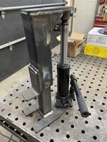
The argon cylinder is secured with a large U-bolt with a piece of high-pressure air hose on it for padding, and the cylinder is pulled snugly against a V-shaped pair of angles welded to the frame, with a chunk of conveyor belt for padding. The cylinder doesn't contact the screw that holds the padding on the frame, as I designed it to leave a gap in the middle. I don’t like cylinders to clank around when moving a cart (it’s just a “thing” of mine), and this setup holds the cylinder securely...and quietly. I also added some pieces of conveyor belt as spacers/bumpers to fit the welder snugly into the top shelf, so that it can't slide around, plus a strap to further secure the welder.

I made a set of low-cost filler-rod tubes from schedule 40 PVC electrical conduit. The tubes have male and female thread adapters where the top and bottom sections connect, and by using a thick O-ring, the tops screw on easily and stop against the O-ring before the threads get screwed on far enough to start binding. I had to sand off the raised letters on the edge of the female adapter to allow a tight seal against the O-ring. I fashioned internal plugs for the top and bottom ends out of slices of solid PVC rod, sanded them a bit to fit snugly, and solvent-glued them in. The tops might look open in the photos, but that's only because the plugs are darker than the conduit. The plugs eliminated the need for PVC fittings at the top and bottom, which allows me to slide the tubes in and out of the steel rings that I welded onto the sides of the cart. Here are a few views of the cart:

rear-view-of-cylinder-clamp.jpg

filler-rod-tube-holder-rings.jpg

front-view-with-welder-cropped.jpg

cart-left-side-cropped.jpg

tig-cart-three-quarter-right-side-cropped.jpg

Future modifications might include mounting a short metal tube somewhere on the cart to hold short pieces of filler rod, and maybe a built-in rest for a TIG torch. I might also try to figure out some sort of drawer or bin for the accessories. The only consumables that I carry on the cart are filler rods. My workshop is small enough that the other TIG consumables are just a few steps away.

My standard disclaimer: I do not guarantee the safety, efficacy, or applicability of any of my designs or ideas that I have described here in this thread. Any use of my designs or ideas is entirely at your own risk.
 
To avoid these ads, REGISTER NOW!
Top Bottom