To avoid these ads, REGISTER NOW!

Soldering copper air piping question

rjprice

Well-known member
Joined
Jan 5, 2006
Messages
64
Location
tx
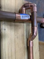
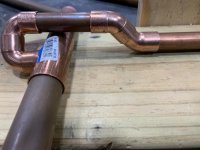
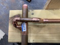
I am about to begin installing copper air piping in my 40x60 shop. 3/4" pipe and 1/2" drops.

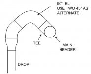
I have plywood walls and will be attaching the piping near the top of the 8ft wall. I attached some pictures of a mock-up of an air drop and was was wondering if I need to solder all of these pieces at the same time of if I can solder them in 2 steps?

I was thinking I could solder the 3/4" tee, the two street 90s and the short 1/2" pipe together in one step and then the two street 45s and the rest of the drop in the second step? Is there a better way? Suggestions???
 

Attachments

  • IMG_1552.jpg
    IMG_1552.jpg
    93.9 KB · Views: 319
  • IMG_1553.jpg
    IMG_1553.jpg
    137 KB · Views: 265
  • IMG_1554.jpg
    IMG_1554.jpg
    150 KB · Views: 241
To avoid these ads, REGISTER NOW!

pbon

Well-known member
Joined
May 14, 2017
Messages
3,498
Why can’t the Tee point down so you don’t need all the extra joints?
 

BD1

Well-known member
Joined
Mar 18, 2007
Messages
4,602
Location
north side
Why can’t the Tee point down so you don’t need all the extra joints?


Tee UP provides the driest air possible. The horizontal main can be pitched with a blow down drain at the end of main.

As for your piping, you could anneal the drop and form the 45 set as needed and avoid fittings.

If you dry fit the fittings out if the tee, use Sharpie to mark position, and prefab.
Then you'll only have the top of the tee to do.


Sent from my iPhone using Tapatalk
 

LS6 Tommy

Well-known member
Joined
Dec 27, 2013
Messages
26,162
Location
Northern NJ
I'd skip all the ells. Tee straight down and have a drip leg and a blow down ball valve on the bottom of the drop, just below the takeoff. That's how industrial runs are done. If you use any high demand air tools the moisture will follow the airflowup a vertical tee anyway.

Tommy
 

BD1

Well-known member
Joined
Mar 18, 2007
Messages
4,602
Location
north side
I'd skip all the ells. Tee straight down and have a drip leg and a blow down ball valve on the bottom of the drop, just below the takeoff. That's how industrial runs are done. The moisture will follow the airflowup a vertical tee anyway.

Tommy


Drops taken off bottom as you stated can be done with a blow down valve setup. That vale and fittings will surpass the cost of the fittings used on the main .
All commercial air piping we do is always off the top of main. Most engineers require this.
These are system where they want dry air.
Big dollar driers and filters are installed.


Sent from my iPhone using Tapatalk
 

joeswamp

Well-known member
Joined
Jul 25, 2007
Messages
2,418
Location
Massachusetts
Another way to simplify it is to space the 3/4 a little further off the wall. That way the drop leg just goes up and behind it.
 

LS6 Tommy

Well-known member
Joined
Dec 27, 2013
Messages
26,162
Location
Northern NJ
Drops taken off bottom as you stated can be done with a blow down valve setup. That vale and fittings will surpass the cost of the fittings used on the main .
All commercial air piping we do is always off the top of main. Most engineers require this.
These are system where they want dry air.
Big dollar driers and filters are installed.

That's kind of outdated engineering. Modern lab quality clean air systems pipe straight down as there is zero moisture content or oil in the main anyway. You need a blowdown at the bottom of a T/O no matter what. The SOP for using clean air in a lab or pharma plant requires it to be blown down at the T/O before hooking up to the equipment to purge particulates introduced from assembly/disassembly of the lines, then another blowdown at the actual equipment. :thumbup:

Tommy
 

matt_i

Well-known member
Joined
Mar 14, 2008
Messages
10,726
Location
SE Michigan
You can of course solder in 2 steps.

But, I prefer to do it all at once, the heat conducts and makes the next joint go faster.

A fitting that got heated but not soldered, I clean again because usually a light oxide layer develops that interferes with the wetting of the solder.

If you solder that close to the wood, be careful and don't vacate the area immediately after completion.
 

56Mark

Well-known member
Joined
Oct 26, 2014
Messages
359
Location
Fall Branch, TN
That's kind of outdated engineering. Modern lab quality clean air systems pipe straight down as there is zero moisture content or oil in the main anyway. You need a blowdown at the bottom of a T/O no matter what. The SOP for using clean air in a lab or pharma plant requires it to be blown down at the T/O before hooking up to the equipment to purge particulates introduced from assembly/disassembly of the lines, then another blowdown at the actual equipment. :thumbup:

Tommy

Who has lab quality air at home? I have designed industrial pump and pipe systems for years and some of that was plant air. I work in a very large plant where we have hundreds of buildings and thousands of HP of air compressors and generally our plant air is not that dry. Where needed, we install refrigerant or desiccant dryers and filtration. I always take the air off of the top of the header. Sometimes, will increase the pipe size at the take off to slow the velocity and let the water fall out. We do this sometimes with small tanks referred to as "knock out pots".

I did my home similar to what the OP has shown, minus the 45's; I went behind and down the wall with 2 90's. Header is sloped with a drain at the end. I have a two stage, 5 HP Quincy and never notice any moisture coming out the exhaust of my tools like I used to when running a smaller compressor with rubber hose.
 

Firebrick43

Well-known member
Joined
May 12, 2015
Messages
14,032
Location
West central Indiana
How many drops are you doing? A ridgid ratcheting pipe bender bought off eBay could easily pay for all those fittings if you do many. If you were closer I would let you barrow mine. 358 for 1/2 copper pipe (type L) and 378 for 3/4” copper (type L)
Paid about 130$ each for mine in really nice condition on eBay.
 

theoldwizard1

Well-known member
Joined
Feb 22, 2011
Messages
43,142
Location
SE MI
Hint : If you have not done a lot of soldering, find some solder with lead in it. Much easier to work with.
 

Terry D

Well-known member
Joined
Mar 25, 2015
Messages
2,202
Location
St. Louis, MO.
I also at first thought, just turn the tee down. But after reading the entire thread, it makes all the sense. Learn something new everyday.
 
OP
R

rjprice

Well-known member
Joined
Jan 5, 2006
Messages
64
Location
tx
Thanks to all who have posted replies. Ill probably do 5 drops.

I was going to put a ball valve at the bottom of each drop, too. If I plan to do that, should I tee off the bottom?

DUH on the going behind the header. Those street 45s are about $2 each so easier and cheaper. Genius!
 

Firebrick43

Well-known member
Joined
May 12, 2015
Messages
14,032
Location
West central Indiana
Yes to the tee maybe 6” up from the valve. The idea is the droplets have more mass and continue on straight and the lighter air makes the 90. Yea for 5 drops a bender does not make sense.
 

LS6 Tommy

Well-known member
Joined
Dec 27, 2013
Messages
26,162
Location
Northern NJ
Who has lab quality air at home? I have designed industrial pump and pipe systems for years and some of that was plant air. I work in a very large plant where we have hundreds of buildings and thousands of HP of air compressors and generally our plant air is not that dry. Where needed, we install refrigerant or desiccant dryers and filtration. I always take the air off of the top of the header. Sometimes, will increase the pipe size at the take off to slow the velocity and let the water fall out. We do this sometimes with small tanks referred to as "knock out pots".

I did my home similar to what the OP has shown, minus the 45's; I went behind and down the wall with 2 90's. Header is sloped with a drain at the end. I have a two stage, 5 HP Quincy and never notice any moisture coming out the exhaust of my tools like I used to when running a smaller compressor with rubber hose.

I didn't mean to come across the way I did. I just meant the whole tee up methodology is not really used as much as it used to be. Most uses that require reasonably dry air have point of use dryers and a homeowner that is not doing any paint work won't even need it, especially with a blow down at the T/O. In any event, there is absolutely nothing wrong with going tee up. :thumbup:

Tommy
 

PWC Repair

Well-known member
Joined
Dec 27, 2012
Messages
3,178
Location
Arkansas
When I did all my piping on my radiant heat system I built it trying to work the last joint to be done in the easiest position possible. Like in your pic I would assemble from the top of the tee to the 45 on the drop. 45 already solderd to the drop. Reason being, last 2 joints will both be flowing down into the joint and easier to make nice.
 

dkroth

Well-known member
Joined
Mar 11, 2010
Messages
3,067
Location
Rochester, New York
I don't doubt the tee-up method has some benefit. However, I also expect high volume applications like media blasting and certain air tools will simply carry the moisture up and over.

If you need clean, dry air, you need a system with the correct components to reliably create it.


.
 

Snip

Well-known member
Joined
Jan 9, 2011
Messages
446
Location
Crossville, Tennessee
One thought, the OP could take 2 thin (18-20 ga) sheet metal or aluminum and place a small section of old welding blanket sandwiched between them and slide it behind the heat affected zone and reduce the risk of damage to the combustable materials. This added thickness may require spacing the upstream and downstream piping away slightly from the wall to maintain straight runs after soldering.
I myself like the idea of drawing the air off of the top of the main and plan on doing this in my future shop along with a valved drop/blow-off at the bottom of each leg.
 
To avoid these ads, REGISTER NOW!

johninct

Well-known member
Joined
Dec 21, 2010
Messages
2,595
T up. Solider any way that is easier for you. I did 3/4" drops so I have plenty of air. You never know your air needs in the future.
 

kelpaso1

MEMBER EMERITUS
Joined
Sep 28, 2009
Messages
3,962
Location
New Brunswick
Not worth the work or expense going tee up like you show. That many elbows and change of direction of the air greatly reduces cfm to the tool at the end.
 

The Cobbler

Super Moderator
Staff member
Joined
Oct 24, 2013
Messages
25,879
Location
Niagara Region, Ontario, Canada
I ran my main line below the outlets , so the tee points up, and a short section of pipe, then the 90°.
Op. to reduce your fittings, turn the tee facing out , use 2 90°. the moisture will lay on the bottom of the pipe. the branch is higher than the run. you won't get any water out of the branch . pitch the main down with a drain at the end
 

American Locomotive

Well-known member
Joined
Jan 8, 2017
Messages
10,953
Location
Rhode Island
You can do Tee-Up if you want, but it's not really going to make a difference for average homeowner stuff. I'd just have the blow-down valve at the bottom and save the hassle of doing all that extra soldering.
 

matt_i

Well-known member
Joined
Mar 14, 2008
Messages
10,726
Location
SE Michigan
The tee-up is just fine, although the trunk line needs its own drip leg drop at the end or low-point (if purposely sloped). A person could save on a lot of cash if they had one drip leg instead of 10. As was mentioned all of the ball valves add up.

Personally I wouldn't worry about the extra fittings, this is ~100psi air not ductwork fed by a squirrel cage fan. The bigger factors are the length of the pipe/hose and quick connectors.
 

SimS

Well-known member
Joined
Jun 11, 2007
Messages
62
If you want to keep the tee-up, what about a short 3/4 flex line/hose to make the transition to the vertical?
SimS
 

Iron-Iceberg

Well-known member
Joined
Feb 14, 2006
Messages
887
Location
A-town
Back to the original question.
Start soldering at the lowest point. The heat will travel up. If you start at the top you will have to wait for each joint to cool before you start the one below it or the solder will run out of the upper joints.
After the first lower joint the rest will be pre heated and go really fast.
Just my experience.
 

Mr onetwo

Well-known member
Joined
Apr 6, 2011
Messages
2,008
Location
Coastal Maine
I would space all the piping out from the wall about 4" , take your drops off the top, turn them straight back and down the wall (eliminating the 45's) standing off about 2" and terminate with a ball valve and tee arrangement.Pitch the main to a drain and you should be nice and dry.Maybe old school engineering, but has worked for 100 years.Read the attached blurb from TiP:thumbup:
 

Attachments

  • Capture.jpg
    Capture.jpg
    156.4 KB · Views: 159

Mr onetwo

Well-known member
Joined
Apr 6, 2011
Messages
2,008
Location
Coastal Maine
if you want to eliminate joints and get fancy, you could employ these little jewels:bounce:
 

Attachments

  • 12 return bends.jpg
    12 return bends.jpg
    105.8 KB · Views: 202

4 FN 27

ALLIANCE MEMBER
Joined
Oct 19, 2015
Messages
4,635
Location
Minnesnowta
Go up and over on your Drops and straight down on your Drip Legs.

Every foot of Copper Tubing adds to your "Reserve Tank". Don't worry about pressure drops because of elbows. Elbows are not as restrictive as FLR's, Regulators and Connections. Yes they do impede but hardly enough to notice a measurable difference unless you are running a very small main Loop.

Here are some pics. The only thing I would have done different is my up and over Drops is I would have went 4 inches up before going over. I have not had any issues ever in any system I have done like this.

My preference is to create a loop around each room so it is dual fed from both directions at the Drop. This lessens the pressure drop. Understand you are still pulling from a single source of air but the Loop becomes the Reserve.

I try to put a Drip Leg in every corner of every room.

If you haven't purchased materials yet I would suggest you step up to 1 inch on your main Loops...if you have the 3/4 will do fine too.

Drop on the right, Drip on the Left:

attachment.php


attachment.php


attachment.php
 

Attachments

  • IMG_8088.jpg
    IMG_8088.jpg
    102.3 KB · Views: 497
  • IMG_8086.jpg
    IMG_8086.jpg
    79 KB · Views: 497
  • IMG_8085.jpg
    IMG_8085.jpg
    77.2 KB · Views: 494
OP
R

rjprice

Well-known member
Joined
Jan 5, 2006
Messages
64
Location
tx
Awesome work! Thanks, these are exactly the pictures I have been looking for.
 

engineer2

Well-known member
Joined
Dec 13, 2009
Messages
11,798
Location
Chicago burbs
Up and over is what I was taught by my old man. Your aftercooler will reduce moisture or your air dryer remove it, but what if either of those fail? It's just added insurance. Our course, you main run will slope towards a drain valve. We never get water in the drain legs unless the air dryer breaks down, which has happened once.
 

Attachments

  • pipedrop.jpg
    pipedrop.jpg
    14.6 KB · Views: 42

Miss the Pontiacs

Well-known member
Joined
Nov 7, 2016
Messages
16,450
Location
Saskatchewan Canada
Back to the original question.
Start soldering at the lowest point. The heat will travel up. If you start at the top you will have to wait for each joint to cool before you start the one below it or the solder will run out of the upper joints.
After the first lower joint the rest will be pre heated and go really fast.
Just my experience.

I xcellent point :thumbup:

4FN27. That is a really nice job:bowdown:
 
Last edited:

nadogail

Well-known member
Joined
Jan 23, 2009
Messages
31,946
Location
Coronado, CA
For Compressed Air Pipelines I use 50/50 solder. You will not find it at Home Depot, I get mine from an Industrial Supply House. They sell it for sheet metal work.
 
OP
R

rjprice

Well-known member
Joined
Jan 5, 2006
Messages
64
Location
tx
Go up and over on your Drops and straight down on your Drip Legs.

Every foot of Copper Tubing adds to your "Reserve Tank". Don't worry about pressure drops because of elbows. Elbows are not as restrictive as FLR's, Regulators and Connections. Yes they do impede but hardly enough to notice a measurable difference unless you are running a very small main Loop.

Here are some pics. The only thing I would have done different is my up and over Drops is I would have went 4 inches up before going over. I have not had any issues ever in any system I have done like this.

My preference is to create a loop around each room so it is dual fed from both directions at the Drop. This lessens the pressure drop. Understand you are still pulling from a single source of air but the Loop becomes the Reserve.

I try to put a Drip Leg in every corner of every room.

If you haven't purchased materials yet I would suggest you step up to 1 inch on your main Loops...if you have the 3/4 will do fine too.

Drop on the right, Drip on the Left:


Very nice work. You mind if I ask where you got the wall mounts? Did you make them?
 

Leaflessshadetree

Well-known member
Joined
Aug 1, 2013
Messages
7,152
Location
Don't ask.
I'd space the main line off the wall. I'd also prebuild the drops all the way to the Tee.
Depending on length and spacing between drops I might prebuild entire sections then just have a few connections to solder once its all hung.
 
To avoid these ads, REGISTER NOW!
Top Bottom