To avoid these ads, REGISTER NOW!

Soldering copper air piping question

4 FN 27

ALLIANCE MEMBER
Joined
Oct 19, 2015
Messages
4,635
Location
Minnesnowta
Very nice work. You mind if I ask where you got the wall mounts? Did you make them?

Like everything else I make them if I can...and I did.

.120 thk 2 x 2 304 Stainless Plates. Ordered 3/8 x 1 and 3/8 x 3 Set Screws from McMaster and plug welded them to the plates.

Laid out the system on the computer and came up with all the cut sizes for the little parts and made them on the Lathe saving me the headache of trying to clean every piece.

Also bought 1/2, 3/4 and 1 inch Internal Brushes and adapted them to work in a Cordless Drill saving more time.

I pre-assembled as much as I could on the bench.

It does take some planning to do it this way.
 
To avoid these ads, REGISTER NOW!
OP
R

rjprice

Well-known member
Joined
Jan 5, 2006
Messages
64
Location
tx
Like everything else I make them if I can...and I did.

.120 thk 2 x 2 304 Stainless Plates. Ordered 3/8 x 1 and 3/8 x 3 Set Screws from McMaster and plug welded them to the plates.

Laid out the system on the computer and came up with all the cut sizes for the little parts and made them on the Lathe saving me the headache of trying to clean every piece.

Also bought 1/2, 3/4 and 1 inch Internal Brushes and adapted them to work in a Cordless Drill saving more time.

I pre-assembled as much as I could on the bench.

It does take some planning to do it this way.

Awesome. I may make my own, too. Thanks.
 

nadogail

Well-known member
Joined
Jan 23, 2009
Messages
31,948
Location
Coronado, CA
I would space all the piping out from the wall about 4" , take your drops off the top, turn them straight back and down the wall (eliminating the 45's) standing off about 2" and terminate with a ball valve and tee arrangement.Pitch the main to a drain and you should be nice and dry.Maybe old school engineering, but has worked for 100 years.Read the attached blurb from TiP:thumbup:

Why argue with 100 years of proven success?
 
OP
R

rjprice

Well-known member
Joined
Jan 5, 2006
Messages
64
Location
tx
Can't wait to see the finished system!!!

I love Pneumatic Management!!!

I was wondering if you welded those set screws with mig or tig? Were the set screws zinc plated or plain steel? Also, how far apart were the pipe brackets?

Reason I ask is I can buy copper plated brass or galv mounting plates that are pre-threaded for about $2. A piece of threaded rod, the split clamp and a couple of nuts add another $3. About $5 per bracket. Really adds up....

This is quick connect/drain setup I plan to use at each drop. The ball valve will be much lower than shown:
 

Attachments

  • IMG_1474 (002).jpg
    IMG_1474 (002).jpg
    129.5 KB · Views: 109

4 FN 27

ALLIANCE MEMBER
Joined
Oct 19, 2015
Messages
4,635
Location
Minnesnowta
I was wondering if you welded those set screws with mig or tig? Were the set screws zinc plated or plain steel? Also, how far apart were the pipe brackets?

Reason I ask is I can buy copper plated brass or galv mounting plates that are pre-threaded for about $2. A piece of threaded rod, the split clamp and a couple of nuts add another $3. About $5 per bracket. Really adds up....

This is quick connect/drain setup I plan to use at each drop. The ball valve will be much lower than shown:

Everything is Stainless. The Plate and the Set Screws. Thus TIG Welded.

The "Make or Buy" decision is personal preference. I make what I can as practice. However if time is an issue then I buy.

Your quick connect/drain setup looks good. You are smart using Brass fittings. Iron Pipe fittings rust on the inside introducing contaminants into your air supply.

Your drip leg doesn't have to be too long unless you are making a lot of water with your air. And I mean a lot of water.

I would suggest using Pipe Dope instead of Teflon Tape on your fittings. Teflon Tape tends to migrate as a contaminant through the system at first. The small piece that break off go through your tools and if your painting can really raise heck with your Paint Gun.

I tend to stay away from Threaded Fittings where ever possible when moving air. A properly soldered join will not and cannot leak. NTP can at times be a real pain to get them to 100% seal...again my opinion because I hate air leaks.

In our Fabrication Shop we "can" feed the entire operation using a 30HP Screw Compressor. In the system there is a 30 and 50HP Screw. The 50 is the Lead Compressor and the 30 is the Lag. We have a 2 inch Main Feeder Loop through out the 110,000 sq ft facility using 1, 3/4 and 1/2 Drop to machines depending on volume required. We have 1868.2 feet of 2 inch copper on the ceiling and hundreds of Drops. The system is laid out in a grid so we can shutdown areas should we have to add a new drop while keeping the rest of the plant operational. The only place there is a Threaded fitting is at the end of a drop or at the Regulator System.
 

sberry

Banned
Joined
Jun 18, 2005
Messages
35,747
Location
Brethren, Michigan
I was wondering if you welded those set screws with mig or tig? Were the set screws zinc plated or plain steel? Also, how far apart were the pipe brackets?

Reason I ask is I can buy copper plated brass or galv mounting plates that are pre-threaded for about $2. A piece of threaded rod, the split clamp and a couple of nuts add another $3. About $5 per bracket. Really adds up....

This is quick connect/drain setup I plan to use at each drop. The ball valve will be much lower than shown:

What is it a guy is gonna plug in there x2? We had an engineer in for something and one of the things he noticed was the air. NO hydrants, all the hoses and the reels a user needs screwed to the hydrants and the only coupler is at the tool end of a hose on a reel.
At the risk of being rude here the workmanship is fantastic, no argument with that but the design here lacks and the main reason is a whole bushel of fittings where 1 or 2 would do. The goal is to make a system that works, that is adequate and meets demand rather than see how many fittings and how much money can be parked in it.
All that might be irrelevant to the OP but its worth noting due to the fact that lots of other guys will try to emulate it at the expense of real useful stuff they would gain some return from.
14 fittings in that 1 cluster alone. Another 7 or 8 in the drop above it, 20 fittings to put in a hydrant.
 
Last edited:

sberry

Banned
Joined
Jun 18, 2005
Messages
35,747
Location
Brethren, Michigan
I could have possibly removed 1 from this yet, doesn't even have a drain prior to the filter, the filter is the catch. Local ball valve ahead of it. Only coupler is on the reel connected to it.
I just looked at one of my own could have reduced a handful on,,, after I did it might have changed the design a little but its irrelevant to the operation, took about 5 minutes with ready made screwed free or cheap parts, made the length work out, would have had to change a couple mounting brackets and add a fitting to the secondary so it was a wash.
I am not immune to doing it, when I started plumbing I had to use every fitting they ever invent but the longer I go the simpler I get, the better it works.
 

Attachments

  • air reggie.jpg
    air reggie.jpg
    75.2 KB · Views: 60
Last edited:

sberry

Banned
Joined
Jun 18, 2005
Messages
35,747
Location
Brethren, Michigan
I need to get a pic of a replacement boiler my bud a masta did. He did it for me, gave me a deal that I couldn't do it myself for but the parts and the design were interesting. I added new electric service to it but gas fired hot water with 4 or 5 zones. I paid the bill on delivery from the jobber, a generic slant fin type job and a box of 90 decree elbows 3 sticks of 3/4, a 4 t maybe, a couple threaded male adapters and a valve or 2.
He might have used a couple other fittings from the truck but he does this on auto pilot, he is a ****** contractor and should do this one simple thing but put a 100 of them in and while there are some pipe runs on some pieces slightly longer than they got to be , added up to well less than a stick build all the turns out of 50 cent elbows and scrap pipe so to speak got a buck and I more joint to solder in to a turn vs matching 3$ street L and even 45 cost some extra.
I bought a box of stuff a while back 3/4 copper, some 1/2 in a bucket where the customer bought the stock and had a bunch of left over special fittings. Lots of them 3$. Common 3/4 90 was 65 cents at a box store.
This could even go over the top with 2 90 and put a kink in the pipe to match any kind of hanger, since its on a branch and tree, might have connected equipment, the right connection eliminates disconnecting charged sections of hose under pressure.
Ist fitting in the drop pipe when its part of the branch tree is a valve that totally disconnects the following equipment. following the valve,,, a ****** from the common pipe and a threaded adapter if going in top or a 90 /******/adapter if I gonna go in the side of a filter if needed or screwed fitting or hose reel on. A filter doesn't hurt, some places like common garaged can use a common secondary regulated
 

4 FN 27

ALLIANCE MEMBER
Joined
Oct 19, 2015
Messages
4,635
Location
Minnesnowta
What is it a guy is gonna plug in there x2? We had an engineer in for something and one of the things he noticed was the air. NO hydrants, all the hoses and the reels a user needs screwed to the hydrants and the only coupler is at the tool end of a hose on a reel.
At the risk of being rude here the workmanship is fantastic, no argument with that but the design here lacks and the main reason is a whole bushel of fittings where 1 or 2 would do. The goal is to make a system that works, that is adequate and meets demand rather than see how many fittings and how much money can be parked in it.
All that might be irrelevant to the OP but its worth noting due to the fact that lots of other guys will try to emulate it at the expense of real useful stuff they would gain some return from.
14 fittings in that 1 cluster alone. Another 7 or 8 in the drop above it, 20 fittings to put in a hydrant.

I could have possibly removed 1 from this yet, doesn't even have a drain prior to the filter, the filter is the catch. Local ball valve ahead of it. Only coupler is on the reel connected to it.
I just looked at one of my own could have reduced a handful on,,, after I did it might have changed the design a little but its irrelevant to the operation, took about 5 minutes with ready made screwed free or cheap parts, made the length work out, would have had to change a couple mounting brackets and add a fitting to the secondary so it was a wash.
I am not immune to doing it, when I started plumbing I had to use every fitting they ever invent but the longer I go the simpler I get, the better it works.

I need to get a pic of a replacement boiler my bud a masta did. He did it for me, gave me a deal that I couldn't do it myself for but the parts and the design were interesting. I added new electric service to it but gas fired hot water with 4 or 5 zones. I paid the bill on delivery from the jobber, a generic slant fin type job and a box of 90 decree elbows 3 sticks of 3/4, a 4 t maybe, a couple threaded male adapters and a valve or 2.
He might have used a couple other fittings from the truck but he does this on auto pilot, he is a ****** contractor and should do this one simple thing but put a 100 of them in and while there are some pipe runs on some pieces slightly longer than they got to be , added up to well less than a stick build all the turns out of 50 cent elbows and scrap pipe so to speak got a buck and I more joint to solder in to a turn vs matching 3$ street L and even 45 cost some extra.
I bought a box of stuff a while back 3/4 copper, some 1/2 in a bucket where the customer bought the stock and had a bunch of left over special fittings. Lots of them 3$. Common 3/4 90 was 65 cents at a box store.
This could even go over the top with 2 90 and put a kink in the pipe to match any kind of hanger, since its on a branch and tree, might have connected equipment, the right connection eliminates disconnecting charged sections of hose under pressure.
Ist fitting in the drop pipe when its part of the branch tree is a valve that totally disconnects the following equipment. following the valve,,, a ****** from the common pipe and a threaded adapter if going in top or a 90 /******/adapter if I gonna go in the side of a filter if needed or screwed fitting or hose reel on. A filter doesn't hurt, some places like common garaged can use a common secondary regulated

sberry while I sincerely respect your :bowdown:"Minimalist Lifestyle":bowdown: in everything you do...some of us are just wired different and our purpose is to keep Fitting Companies in business:beer:...and come up with things that fit our own personal needs.

I could get by with a 100 ft Air Hose hooked up to the end of my Compressor but I wanted an air system, Looped and double fed with drops and drips everywhere I want/need one. That is just me...I do what I do and you do what you do. And both work...I know I am happy and I suspect you might be too with your accomplishments...

All is good...
 

sberry

Banned
Joined
Jun 18, 2005
Messages
35,747
Location
Brethren, Michigan
Pat mentions screwed. I like it all screwed at the end. I agree that leaks are a non deal soldered and with 1/2 I am bad if I use a pipe wrench but need to stay with the channelocks with screwed. I am more a 3/4 guy due to the fact it feels good with a wrench.
For most small garages some simple manifold/piping, could be some simple pieces and all 1/2. Using 1 thing at a time, one size pipe, less reduction. Steel pipe is closer to 5/8 than 1/2. Even in a big garage the 1/2 works cause its got 100 ft of pipe but only 1 elbow and straight in to the equipment.
 

sberry

Banned
Joined
Jun 18, 2005
Messages
35,747
Location
Brethren, Michigan
My coments were not aimed at anyone in particular even, I tend to look at it as a thing. I understand your position about doing what you want, no argument at all about that, its not going to effect your bottom line, in the scheme wont hurt a thing.
Most people want to be artist or are masters are not asking, I am tending to consider that and in a how to solder this all up I gonna say reduce several times for best design, we got some comment about losses thru the turns but this is so over kill its rather moot. Whats another 5$ for the hanger when we got a hundred in parts at every drop just to turn a little air 90 degrees.
3rdly,,, if I was going to solder it up might build it on the floor and hang most of it. Might even leak test. I think there was another piece added to this deal yet. It was a little work to get all the features in as few pieces. As for losses thru the turns here, all 3/4 before running on to 1/2 branches. While I might work on a truck or a tractor I am not a truck tire service center either.
I am a believer in pipe, nothing wrong with it even when a hose would do. Where a hose can work is test and prototype, temp. Work the geometry out and then pipe it. I stopped what I was foing to fix one a while back, changed the design from when I first built it and moved the hydrant about 20 ft to make it a walk up plug for sandblast and another routine chore. The original looked good on paper but ended up parking something in front of it and it made it a circus act with a hose to use it.
 

Attachments

  • air pipes.jpg
    air pipes.jpg
    118.9 KB · Views: 36
Last edited:
To avoid these ads, REGISTER NOW!

rattle_snake

Well-known member
Joined
Jun 25, 2015
Messages
5,194
Location
Chandler, AZ
FWIW, another vote to skip up-n-over in a home shop....

Keeping the condensate in the main line, at the same time using it to deliver air isn't ideal. I'd rather get it out of the main line into a drop, where it can be drained. So unless you plan to have dedicated condensate drops like 'FN..... (bad *** system by the way!)

Also, I have not observed any reference to 'PVC' in this thread yet.
:headscrat
 
Last edited:

sberry

Banned
Joined
Jun 18, 2005
Messages
35,747
Location
Brethren, Michigan
I would vote tee down and dip leg with drain after the outlet.

03D49DFB-213D-490A-8B21-80CD2DECD74B.jpg

If this branch and t like a valve ahead of the t to shut off any connected equipment, local disconnect. Nice for build as you go, can turn off as needed, turns off hoses and reels in some cases without turning off rest of system or other drops.
 

sberry

Banned
Joined
Jun 18, 2005
Messages
35,747
Location
Brethren, Michigan
If you want to keep the tee-up, what about a short 3/4 flex line/hose to make the transition to the vertical?
SimS

Not really, ideally the main should be hard pipe, any rubber, hoses, unions, regulators after a ball valve. Look where the valve is. On the hard drop. Some more simple systems may use the service valve at the comp, more advanced systems an additional local valve.
Pic 3 was plumbed in to an existing mount, I could have moved the bracket and plumbed straight in to the top of the filter, simply screwed it on but had a whole box of stuff in front of me including ready made ******* where it all came to length let me tighten it in place after the valve. It was so easy.
 

Attachments

  • air 4.jpg
    air 4.jpg
    71.1 KB · Views: 30
  • air reggie.jpg
    air reggie.jpg
    75.2 KB · Views: 28
  • paint air dis.jpg
    paint air dis.jpg
    43.2 KB · Views: 34
Last edited:

4 FN 27

ALLIANCE MEMBER
Joined
Oct 19, 2015
Messages
4,635
Location
Minnesnowta
Every bend you put in there slows your flow. 'fluid dynamics' at play whether it's water or air.

we got some comment about losses thru the turns but this is so over kill its rather moot.

sberry nails it right here!!! Thanks sberry for getting me out of my chair last night and getting online to do a little learning.

I have often heard elbows reduce flow or create pressure drops...I agree but to what extent? So I did a little digging...and I am in no way an expert to the level of a physicist that would understand the dynamics of Pressure Loss Coefficient (PLC) formulas...and does it matter? My Air System both at home and at the plant have never held me back from doing a job using air because of Elbows and Tee's.

At the end of the day most information I found researching floats back to "Equivalent Pipe Length". Meaning for every Elbow or Tee you introduce to the system it is equal to adding a given length of pipe to the system.

Thus adding 1 90° elbow is the equivalent of adding 6 inches of pipe to a Half Inch Drop. For 3/4 inch 1 90° Elbow would add 8.4 inches of pipe.

So if you do go up and over by adding 2 90° Elbows and a Tee making your drop 32.4 inches shorter and it will net out at a zero loss or gain on a 1/2 inch drop.

The Math:

2 90° is equal to 1 foot of Equivalent Pipe Length

1 Tee (Side Outlet) is equal to 1.7 feet Equivalent Pipe Length

(1 ft = 12 inches) + (1.7 ft = 20.4 inches) = 32.4 inches

This is the simplest chart I could find showing the "Equivalent Pipe Length" method:

attachment.php


Sure beats the formula...:beer:

attachment.php


I am all ears if there is a better formula or chart...or somebody here can break this down further and explain it in a fashion that a guy with more calluses than brains can understand.
 

Attachments

  • Pressure Drop.jpg
    Pressure Drop.jpg
    110.8 KB · Views: 151
  • Pressure Drop02.jpg
    Pressure Drop02.jpg
    56.5 KB · Views: 148

sberry

Banned
Joined
Jun 18, 2005
Messages
35,747
Location
Brethren, Michigan
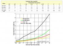
If I study enough I cam make some sense out of the charts and I elude to it some in one of these threads, some regarding fitting capacity or ratings. This chart refers to it in velocity I think, I might go back and look but,,,,,, while all of that does have some effect it is dependant on applied load. The losses would be greater with identical loads in 1/2 than in 3/4. For practical matters for guys on the forum who are loading a pipe,, or wire to 1/2 capacity then it's all moot, got a 3/4 feeding a 1/2 drop to 50 ft of 3/8 hose then the losses down the main is irrelevent. If we are engineering a complex machine running it all out then it's different.
Kind of like improved air filter on an engine, on a 600 hp race car means something at wot, put the same filter on a 4 cyl ant cruise speed not so much to gain at 1/2 throttle. We put a 20A breaker on a circuit and calculate v drop at 20,, then use it for a 7A grinder or 50 watt, or even 500 watt light, drop might be a consideration at full capacity but with a less tool doesn't matter or is irrelevent.
Guys are using 3/4 pipe here, worry about losses wouldn't be a concern with a 1/2 with the tools they are using. Doubly or so considering some of the short distance. Pex has some neat charts, one they publish for 100 ft but another for 60 which is close to most circuits than 100, quite a little difference under max velocity figures, really changes a leap when the load is reduced. A guy can really see this across voltage drop charts for 120v, at 20A starts adding up fast, at 5 is a different matter.
 
Last edited:

sberry

Banned
Joined
Jun 18, 2005
Messages
35,747
Location
Brethren, Michigan
Go up and over on your Drops and straight down on your Drip Legs.

Every foot of Copper Tubing adds to your "Reserve Tank". Don't worry about pressure drops because of elbows. Elbows are not as restrictive as FLR's, Regulators and Connections. Yes they do impede but hardly enough to notice a measurable difference unless you are running a very small main Loop.

Here are some pics. The only thing I would have done different is my up and over Drops is I would have went 4 inches up before going over. I have not had any issues ever in any system I have done like this.

My preference is to create a loop around each room so it is dual fed from both directions at the Drop. This lessens the pressure drop. Understand you are still pulling from a single source of air but the Loop becomes the Reserve.

I try to put a Drip Leg in every corner of every room.

If you haven't purchased materials yet I would suggest you step up to 1 inch on your main Loops...if you have the 3/4 will do fine too.

Drop on the right, Drip on the Left:


Very nice work. You mind if I ask where you got the wall mounts? Did you make them?

This is kind of a poster case for this discussion. How big are the rooms, how much demand? Common tools? 200 200 room or 20x20? Increase to inch to gain 2 gallons and 1# loss? Lose 30# down a hose reel and 1 down the main. Of course regulators reduce pressure,,, it's what they are there for. Losses across connectors only relevant if it effects the use of the tool. In some cases restriction is good, hence the invention of the sink supply tube vs plumbing them direct with 1/2 and it doesn't help running 3/4 especially in the advent of low flow which are restrictor same as in air, the oblect is to get the work from it not to just see how much we can dump which over supply does.
I got some large hydrants, got the supply to back it up for tank filling which is a different load than hand wash.
Very important with limited service, they even build it in to silcocks so opening wide open doesn't drop the incoming to none. Only real hi demand most see is impact, even sandblast is limited by the capacity of the comp. Big hose, big air jet just runs it out past its capacity, you can drain a 5 hp comp quickly with a 3/8 hose, extended sanding, grinding and blasting are limited by comp,, not by hose.
 
Last edited:

sberry

Banned
Joined
Jun 18, 2005
Messages
35,747
Location
Brethren, Michigan
I was running a tool common to many here the other day. 100 ft of 1/2 steel on the hi side to a regulator then 50 ft of half after and 50 thru a 3x8 reel with 2 connectors, 1 being an old automotive I stuck on it as a disconnect. Due to impact had the reg set 130 or so, man the sander was hot I had to turn it's dial down which is a restrictor,, but thought for giggles, all the losses and still 120 at the tool, way too much. Not an issue of not enough but just the oposite.
 

sberry

Banned
Joined
Jun 18, 2005
Messages
35,747
Location
Brethren, Michigan
Pat, you ever get any water down the drip leg?
I did a redesign. I had underfloor plastic I put in a hurry/cost when I built. It worked but collected water in the filters. It didn't seem to hurt, not sure how it did with plasma nozzles but never got it in the paint filters but,,, I abandoned it and totally redesigned the mini fold and went to vertical and overhead steel.
Re did 3 drops, 2 didn't put any thing in and ran right in to the filter, 1 has a 2 ft over the top feed, that is understandable but all goes to the other run, not a drop in the filter. I put a Drip in the other one, wouldn't have needed it, was only a couple fittings and I cracked the valve a couple 3 times in the years since and none.
The old man if old was somehow flinging drops in to the line went to storage building, it collected water even not in use and just caught it once before it froze off, just barely and had to keep an eye on it, now none. Super dry.
 
Last edited:

4 FN 27

ALLIANCE MEMBER
Joined
Oct 19, 2015
Messages
4,635
Location
Minnesnowta
Pat, you ever get any water down the drip leg?

I have not gotten any moisture to speak of in any of the Drip Legs in the Machine Shop or Car Shop. I tend to crack the valves on occasion when the compressor is just starting to build pressure. This allows me to see droplets vs moisture vapor. Have not seen any to date.

Now at the Compressor I will see a little droplets from the 2 Legs before the Pre and Coalescing Filters. The 2 Legs were installed in case I wanted to add an Industrial Refrigerated Air Dryer.

And during the high humidity of the summer the Pre-Filter will relieve it's self on occasion as well as the Coalescing Filter every great once and a while.

The Drip Leg on the Main Vertical Line will have a few drops too if I am doing a bit of Sand Blasting.

I have an Auto Drain on the Compressor and that will dump a few ounces a day during the summer.

The Compressor is located in what I call the cold storage area. It never gets below 50° in the dead of winter because I heat it. In the summer I keep the whole place sealed up 95% of the time with Air Conditioning in the whole building except the Cold Storage Area. That area stays below 76° all summer for the most part. So the Air remains pretty constant relative to the season we are in.

I also run Dehumidifiers though out the building. Once the humidity hits 40% in any one area I turn on that Dehumidifier. They are set for 35%. So at the peak of the summer there might be 5 Dehumidifiers running at any given time. I hate rust...adding the Water Jet in the system adds to the Humidity issue. For the most part it remains pretty dry.

The Auto Drain:

attachment.php


The Refrigerated Air Dryer Manifold, Pre Filter, Coalescing and Drip Leg on the Main Feeder:

attachment.php
 

Attachments

  • IMG_3878.jpg
    IMG_3878.jpg
    124.7 KB · Views: 161
  • IMG_8091.jpg
    IMG_8091.jpg
    106.6 KB · Views: 162

glentre

Well-known member
Joined
May 21, 2016
Messages
909
Location
Gloucester, Virginia
Looks like you are going to end up with some nice piping runs and you can make it look like a real pro job with a few easy techniques.

First, remove those lousy bar code labels most stores put on every fitting. Soldering the fittings with the labels on will char them & they will look like hell after.

If you don't already have experience, look at some YouTube videos on how to solder properly. After heating the fitting evenly no matter what position it's in, just touch the solder wire to both sides and watch the bubbles which shows the fitting has drawn the solder in. Adding any more solder than that just makes a mess with solder dripping and running all over and even inside the pipe on the top joint of the vertical joints. You never need to build up a bead of solder at the joint.

As soon as the joint (or multiple joints if you are doing a number of fittings at one time) hardens, wipe it all around with a wet rag. This is the easiest way to get rid of the flux residue.

For a really cool looking piping run, steel wool all of your piping and fittings before assembly, clean off the flux after soldering and then add a coat of poly to the whole run so your assembly will look shiny new for years.

Of course, if you are not a neatnick or **** like some of us, you might be just as satisfied ending up with flux that hasn't been removed turning green, several inches of solder that has run down from your vertical joints and sagging solder drips from your horizontal ones. Depends on how nice you want your shop to look...........or not.

Glen
 

sberry

Banned
Joined
Jun 18, 2005
Messages
35,747
Location
Brethren, Michigan
I got a Bud who is a ****** contractor but is a copper pipe whiz, does it on auto pilot. Its neat to watch. Everyone who wants to do this should have the opportunity to watch someone like that sweat out a boiler job.
 
To avoid these ads, REGISTER NOW!
Top Bottom