To avoid these ads, REGISTER NOW!

Super Efficient HRV retrofit with smoke filter for $300?

Denwood

Well-known member
Joined
Sep 22, 2014
Messages
4,192
Location
Thunder Bay, Ontario, Canada
I’m conducting a bit of a science experiment. Can you take an older HRV, (in this case with a known fire hazard motor), and retrofit it as an ECM miser? Model is a Venmar AVS Solo 2…apparently was quite a popular unit. The unit was slated for disposal.
In the initial test (temp probes at all four ports) the HRV is “bench” balanced via a vane anemometer to 88 CFM, using 19 watts total power, with a measured efficiency of 89% over about four hours of testing with outside temps 37-40F. I’m using two EC fans, mounted externally.
The questions are about balancing:

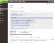
1. There is a balancing chart attached, however my assumption is that it would be useless in the current configuration with the OEM motor and housings removed.

2. If I take measurements of static pressure on the door ports in the new configuration (with measured CFM on 5′ long, 6″ ducts), can I correlate these to balance once fully installed? My thinking is to take statics via the door balance ports at all the motor speeds, measure flow and basically make a new chart.

3. Once the system is fully installed, will the chart I made in step 2 be ok to determine CFM rates?

4. I am not balancing using dampers, but rather EC fan speeds as there are two separate controllers.
I’m hoping some you trade gurus out there will chime in on this one 🙂

Unit in "OEM" configuration:
IMG_8380.JPEG

Motor and housing partially removed.

IMG_8404.JPG

Testing with temp probes two PTC heaters to simulate 70F inside air...

IMG_8401.JPG

Balancing chart on the HRV.

IMG_8412.JPG

I ran my test (heating intake air to about 70F) for about four hours. Sound was measured 1 meter from the motors at 54.5 db. Surprisingly quiet with no silencers (coming later) installed. I was able to spin up the OEM motor (just barely) and tested power use at 300 watts. The motor lower sleeve bearing (poor design that starts fires!) had enough play to allow contact between stator and rotor...so my guess is that a new one would use less power. Still, from the OEM psc motor's rated 210 watts or so, we're down to just 19 watts (including the HRV control, and two motors running).

There is a recall in effect for these, and similar units: https://globalnews.ca/news/6298646/air-exchanger-recall-canada/
You can buy a new motor, but it's $200 for the part, and uses the same (bad) sleeve bearing design. The "safety" device they send out is a plug with an embedded 3 amp fuse. It does not fix the motor issue, but will prevent a fire.

..so, a bit surprised by how well it performed!

IMG_8407.PNG

Balanced at 89 CFM for now using a vane anemometer at intake/exhaust:

IMG_8399.PNG

Sound measurements, about 1 meter from fans at loudest point:

IMG_8410.PNG

Power use by two EC fans and HRV control unit:


IMG_8397.JPEG
 
To avoid these ads, REGISTER NOW!
OP
D

Denwood

Well-known member
Joined
Sep 22, 2014
Messages
4,192
Location
Thunder Bay, Ontario, Canada
I figured this out with a Magnehelic Pressure gauge in hand. The balancing reference chart references air flow measured over the core itself at various static pressures, so it doesn't matter what you do (like removing the OEM motor and a pile of fan shrouding)...you can still use the balancing chart to extrapolate air flow from the ventilator. It's pretty handy in that you can fully install ducting, filtration etc, then dial in your air flow and balance back on the HRV via the door ports :) Rather than using dampers though, you can do everything in this case by changing the EC motor speeds on intake and exhaust to dial things in. That's more efficient.

48443_1666069154_E1C503D5-9B5C-4AA3-9CAD-43209177EBA4-700x1515.png


IMG_8417.JPG
 

PoorUB

Well-known member
Joined
Mar 29, 2021
Messages
11,660
Location
Fargo, ND
I would assume the factory chart should be fairly accurate, after all they are measuring pressure drop across the heat exchanger. How the air gets to the heat exchanger should not matter.

If you want to verify you can mock up a device to measure pressure drop across and orifice. You just need a piece of sheet metal, cut an fairly accurate hole, say four or five inches in diameter, install it in your duct, a long straight run will give the best results, then measure pressure drop at various fan speeds. There is info on the 'net that will give you PD at various CFM.
 
OP
D

Denwood

Well-known member
Joined
Sep 22, 2014
Messages
4,192
Location
Thunder Bay, Ontario, Canada
@PoorUB, thanks :) I did confirm the pressure reading with LFM air flow measurements using a small hand held anemometer, measuring flow at intake and exhaust with about 48" long, 6" diameter ducting on the HRV outside intake and exhaust. It's a bit tricky getting readings (wide variations depending on where you hold the device), but I'm about 100% sure now that the probes are measuring pressure drop across the core, and that restrictions in the ducting are accurately reflected in the balancing flow chart. It's a lot easier to use the Magnehelic diff gauge and likely more accurate...the factory has done the work for us here :)

I'm just waiting for a 14x14x4 MERV 13 filter setup to arrive so I can put the system into play. I've also bench tested a "grow tent" charcoal filter on the system with some fire smoke and it actually worked quite well. I think they are a 100% effective solution for folks with wild fire smoke issues. They are a bit restrictive but I can still get 60 CFM from the system (my target) with the charcoal filter in place. It's basically a canister full of activated charcoal. Not sure if I'll figure an outside (so easy to remove when not needed) setup for this filter, or sort one inside. I would only use it when smoke outside is an issue.

StorePhoto1__30559.jpg
 
OP
D

Denwood

Well-known member
Joined
Sep 22, 2014
Messages
4,192
Location
Thunder Bay, Ontario, Canada
Here is a mock up of the“smoke” configuration of the HRV. The activated charcoal canister is a bit restrictive (drops flow about 7-10 CFM) but it does a good job in my smoke intake tests. Basically this setup replaces the OEM intake filter, and fits in the area formerly occupied by the OEM blower. It will be set up with the baffle plate to just slide in when needed.

B834AC62-00D1-4132-A5A3-AB806EB39A6C.jpeg
 
Last edited:
OP
D

Denwood

Well-known member
Joined
Sep 22, 2014
Messages
4,192
Location
Thunder Bay, Ontario, Canada
My target was 60 CFM delivered constantly and quietly, which we're at...but I'd recommend going with 6" EC fans if you need higher airflow from a setup like this. The fresh air intake side EC fan will need to be on setting 6 or 7 (of 8 speeds) when the carbon filter is in place to deliver 60-65 CFM of air flow. Exhaust (stale air out) only needs to be setting 4 or so to balance that flow. Alternatively, just get a 6" fan for the intake as that is where all the filtration lives :)

I'm still waiting for the 14x14x4 filter housing which will host a MERV13 air filter.
 

u3b3rg33k

Well-known member
Joined
Dec 18, 2017
Messages
4,048
@Denwood have you done any CO2 measurements to see where this puts you? I picked up a meter and found my place was much higher than I anticipated. I've been using my range hood on low/quiet (which should be moving about 100CFM) and a slightly open window, and that brings the numbers in-line with where they should be. obviously this is not a great solution for the heating season.
 
OP
D

Denwood

Well-known member
Joined
Sep 22, 2014
Messages
4,192
Location
Thunder Bay, Ontario, Canada
I've been monitoring C02 levels off an on since installing the Panasonic spot ERV (4-5 years), including logging with a laptop for a few days. Now keep in mind, the home is over 100 years old, and we have only a spot ERV in play. The "new" system will drop fresh air in the living area, and pull air from a stairwell ceiling next the kitchen which in itself will be a big improvement.

My target is 60 CFM based on the fact that with 30 CFM from the Panasonic ERV, the home (with four persons inside) we are sometimes under 700 ppm, but often over. Mornings show the highest levels upstairs (3 bedrooms on 2nd floor) as you'd expect, and this can still go over 1100 ppm. Open a window on the 2nd floor, and the levels drop pretty quickly. This is a bit hard to do at -25 C though.

The main living area (where the fresh air from the HRV will be dumped) is also where the largest two air returns for the forced air furnace are located. At night, the fan is set on the furnace to run continuously at about 450 CFM (to provide air to bedrooms). The furnace uses an ECM motor so at low speed uses very little power.

On windy days (say 30km/h and up ) there is no need for mechanical ventilation and C02 levels drop all by themselves due to air pressure on the building envelope. I measured the same behaviour in our new, super insulated, commercial building...a much tighter building. Co2 levels were always low on windy days.

Doubling supply CFM (while also dramatically increasing efficiency) will double the ventilation rate, but lower the BTU requirement to heat that air. At temps below 20 F, the Panasonic ERV spends about 80% of the duty cycle just exhausting at 20 CFM which is not so great at very cold temps. The Venmar mod'd HRV will spend a lot less time in defrost mode, and when doing so will not be exhausting air.
 
OP
D

Denwood

Well-known member
Joined
Sep 22, 2014
Messages
4,192
Location
Thunder Bay, Ontario, Canada
The filter housing showed up today for the new ventilation system. It allows you to swap in 14x14x4 filters (MERV 13 in this case) which will filter outside air being pulled into the house to a much higher degree than the internal HRV dust filters. I've measured very low resistance It has very low resistance with the 14 x 14 x 4 filter, so mission accomplished :) I'm using masking tape as this setup is very temporary...the final install will use duct seal mastic. I need to take a few measurements and make sure all the bits will fit ok into their final resting place.

IMG_8455.jpg

The filter that came with the unit. I looked at a few YouTube videos comparing filters and learned that the 4" versions flow a lot better simply due to more filter media in play.

IMG_8456.jpg

A few tweaks for better air sealing around the filter:

IMG_8457.jpg

IMG_8458.jpg

Mocking things up to make sure it will all fit...

IMG_8460.jpg

It looks like 60 CFM will be no problem with the filtration in place. I've believe I've also figured out a potential solution to control the motor speeds via the house automation and a few 0-10V dimmers. I've never worked with 0-10V devices (LED lights, EC motors etc.) and it's a bit hard to figure out how everything works. I've checked the AC Infinity motor controller leads (while the fans are running) so it looks like two wires deliver a small amount of current (10V) and the other two provide a signal from 0-10V depending on the desired motor speed. Fingers crossed.

The end goal is varying the individual motor speeds so that balancing can vary dynamically as needed. For example, if the induction cook top/ exhaust fan setup fires up the exhaust fan, the same system can potentially adjust the HRV's ECM motors to balance the house.
 

u3b3rg33k

Well-known member
Joined
Dec 18, 2017
Messages
4,048
That's a beast. What's the application?
taking a printing press from 'mostly ambient' air recirculation (read: room air, fumes) to 100% OA. heater core is for bringing up the air temp in the colder months, HRV is for that whole *heating outside air is stupid* thing. curve says it should recover somewhere around 60% sensible (no latent in this application).
 
OP
D

Denwood

Well-known member
Joined
Sep 22, 2014
Messages
4,192
Location
Thunder Bay, Ontario, Canada
I hear a lot of talk of late regarding air quality just about everywhere I look, particularly post-covid. One of of my best staff came from a printing operation, working under similar conditions which had become an issue for her health. She was pretty happy to be working in a net zero goal space with radiant heat, Co2 monitoring, active night cooling etc.

Tempeff is manufacturing units with that capacity (not cheap) but that can work at 90% sensible with no defrost strategy: https://riada.ca/wp-content/uploads/2020/12/RGSP.pdf
 

u3b3rg33k

Well-known member
Joined
Dec 18, 2017
Messages
4,048
I hear a lot of talk of late regarding air quality just about everywhere I look, particularly post-covid. One of of my best staff came from a printing operation, working under similar conditions which had become an issue for her health. She was pretty happy to be working in a net zero goal space with radiant heat, Co2 monitoring, active night cooling etc.

Tempeff is manufacturing units with that capacity (not cheap) but that can work at 90% sensible with no defrost strategy: https://riada.ca/wp-content/uploads/2020/12/RGSP.pdf
not to hijack your thread too much, but my other HVAC project this year was a DIY(ish) VRF MAU:
upper level piping & actuator.jpegintake.jpegindoor coil.jpegJADE.jpeg
 
OP
D

Denwood

Well-known member
Joined
Sep 22, 2014
Messages
4,192
Location
Thunder Bay, Ontario, Canada
No hijack at all. I love that concept as you've basically done a DIY economizer(ish) that brings in cool air for cooling when outside conditions warrant, yes? Kind of cool that Honeywell has a control for that application.
 
OP
D

Denwood

Well-known member
Joined
Sep 22, 2014
Messages
4,192
Location
Thunder Bay, Ontario, Canada
I've been looking for a solution to automate fan speed on the AC Infinity EC fan motors in my mod'd HRV and have been stumped for two reasons:

1. AC infinity does not "support" any other control of their devices so did not provide any information.

2. Qubino (which sells a 0-10V zWave dimmer device) is only supported for EU zWave frequencies so no joy here in NA.

Enter the Leviton **ZS057-D0Z** which is sold as part of the "Illumina RF" wireless control line of Leviton controls. It's a 0-10V dimmer that is connected and installed as a standard 120V light switch. It has two extra wire leads for the 0-10V device to be controlled. What's not obvious, or listed anywhere, is that this device is actually a standard Zigbee device and can be paired to Hubitat (and I'm sure SmartThings). I purchased two of them from Aartech here in Canada...a great vendor to deal with for automation bits: https://www.aartech.ca/zs057-d0z/leviton-lumina-rf-decora-0-10v-wall-dimmer-2-4ghz.html

IMG_8464.jpg

Terrabloom (I'm using one of their 6" inline EC fans for my kitchen exhaust) answered by queries with a basic "if it's designed to work as a 0-10V dimmer, it will work with their fans. Terrabloom does have a video on creating your own DIY speed control for their EC fans, but you'd be doing a custom Arduino board to do it. They do include a cable with their EC fans for DIY control, so you'd just need to connect two wires from that harness to do it if using the Leviton dimmer:

Leviton violet wire connects to Terrabloom blue
Leviton grey wire connects to Terrabloom black
The other Terrabloom wires are left disconnected (red and yellow)

terrabloom%20DIY.jpg

You just need to set the driver to "Generic Zigbee Dimmer" after inclusion to Hubitat, configure, and save your changes in the device driver interface. Setting the level for the device in Hubitat then controls motor speed..and the setting is also reflected via the green LEDs on the Leviton Dimmer. This means you can both manually control the fan as well as do it via the zigbee wireless protocol and automation hub. This opens up a ton of opportunities to control fan speed based on temperature, occupancy, CO2 sensors etc. etc.

IMG_8465.png


IMG_8466.png

For AC Infinity fans like the Cloudline T6 fan fan pictured here, the connections are pretty simple.

Remove the 4 wires that connect to the AC Infinity remote control, and connect the Levition as below. You can check with a multimeter with the standard controller first to make sure you have the correct wires.

The AC Infinity wire colours (controller is disconnected in this photo) correspond as follows:

Red = +10 Volts to power controller (does not vary with motor speed changes)
Black = ground for +10 Volt power to controler (does not change with motor speed changes)
Yellow = + 0-10 V signal to control motor speed.
White = ground for 0-10 V motor speed control.

Leviton Violet (0-10V signal) goes to AC Infinity Yellow terminal (pictured below)
Leviton Grey wire (ground) goes to AC Infinity Black terminal (pictured below..note the correction in the pic below)

aeb0c1d7850414112a4173247f4e4a9ef15f0c4e_2_375x500.jpeg

I suspect a lot of folks with these fans will want control them via Hubitat and/or Smarthings ...so there you go :)

The above bits will be used to dynamically provide make up air with kitchen exhaust fan use (already automated), vary speed on occupancy and potentially avoid defrost cycles by ramping exhaust over intake when the core temperature drops. Staging is being done here to figure out the package sizing, filtration (MERV 13 via 14x14x4 inline filter). I've also got a solution for filtering wild fire smoke using an internal carbon canister. The OEM motors and housing have been removed from this HRV, hence the external EC fans.

IMG_8460.jpg
 

Attachments

  • IMG_8462.jpg
    IMG_8462.jpg
    168.2 KB · Views: 613
  • IMG_8464.jpg
    IMG_8464.jpg
    158.1 KB · Views: 5
Last edited:

u3b3rg33k

Well-known member
Joined
Dec 18, 2017
Messages
4,048
No hijack at all. I love that concept as you've basically done a DIY economizer(ish) that brings in cool air for cooling when outside conditions warrant, yes? Kind of cool that Honeywell has a control for that application.
Yup it's a honeywell JADE W7220, with 0/2-10V modulating actuators. available as a kit for a fair price, given what it does. because there's no roof curbs, I had to get creative. two modulating actuators run off the same signal, set opposite each other. indoor set to fail open, outdoor air set for fail closed.

it basically becomes a 3 stage AC, where it intercepts the cooling call and goes 100% OA if the weather permits. if the thermostat stages up for more cooling (which calls for high speed fan regardless), it lets you set the delay before it kicks on the condenser (while still running 100% OA, weather permitting).
the ODU is basically an LG minisplit (styled like a regular split) condenser, so it'll ramp up/down based on load. does a great job of dehumidifying the incoming air.

it does all the psychometrics in real time, so it's pretty simple to set up. also has input for an occupancy (CO2) sensor. I measured and found we don't need it (levels are under 600PPM all day) with my minimum damper setting (about 50%), and I don't want it cutting back further, so I haven't bothered to install one.


the economizer also takes an occupancy signal, so during unoccupied hours (part of the thermostat schedule, honeywell prestige IAQ), the dampers close unless the cooling call asks for it.
 
Last edited:
OP
D

Denwood

Well-known member
Joined
Sep 22, 2014
Messages
4,192
Location
Thunder Bay, Ontario, Canada
Here are the two fans now in the automation hub control panel. Ignore the temps/efficiency as the probes are not on the unit right now.

Here are the settings on the Leviton driver that correspond to about "half" speed on the AC Infinity controller. I'm finding the comparative scale on the Leviton units much lower, as you can see by the driver numerical level setting (12=exhaust fan and 30=intake fan) that correspond to 60 CFM measured flow over the HRV core. In other words, the settings 12/100 and 30/100 on the Leviton Dimmer, correspond to settings 5/10 and 6/10 on the AC Infinity controller.

The idea is that when the kitchen exhaust fan is on, or we're having company over, the system can automatically dial up or down exhaust/fan speed settings independently. I'll also be able to monitor the four air streams temps as we get into very cold winter temps (-35 C) and play around a bit with intake/exhaust flows to see if I can avoid defrost (recirc) mode altogether.


a77c477875c5b276574a2e1eab74099298f466ee_2_618x500.jpg
 
To avoid these ads, REGISTER NOW!
OP
D

Denwood

Well-known member
Joined
Sep 22, 2014
Messages
4,192
Location
Thunder Bay, Ontario, Canada
The small Panasonic ERV is out, and I've opened up the "window" to install the larger Venmar unit.

ERV was in the basement stairwell:

IMG_8483.jpg

The open space where the larger Venmar HRV will go:

IMG_8484.jpg

With no ERV/HRV running last night, we saw this in the morning. The reading was from our bedroom, with the door open all night. This is a very high level of C02...the "normal" target is to see levels under 800 PPM.

IMG_8476.jpg

Weather was around 0 C (32 F) with a wind gusts up to 33 km/h. Wind on a very leaky house will ventilate it all by itself, however our 100 year old house has evidently been energy retrofitted to the point that leakage is a lot less.

The Panasonic spot ERV, despite being on the main floor and not connected to the house HVAC, was actually bringing a decent amount of fresh air in as we never saw C02 levels this high with it running.

IMG_8479.png

So now, we'll see how the new unit changes things up in the house :)
 

u3b3rg33k

Well-known member
Joined
Dec 18, 2017
Messages
4,048
I'm tempted to just buy a zehnder. I want the co2/voc sensors, vs wiring them up after the fact to a unit that's basically on/off control. the price tag is just awful though.
also tempted to put a CO2 sensor in for my gas range hood, and control that fan off that. goes over 800, fan goes on/faster. turns off after it clears the air when you stop cooking.
 
OP
D

Denwood

Well-known member
Joined
Sep 22, 2014
Messages
4,192
Location
Thunder Bay, Ontario, Canada
@u3b3rg33k , more or less why I'm going this approach. I have a 24 volt CO2 sensor (not the USB one pictured above) that can feed an automation input.

Once you tie things into an automation system you can do a lot more, like shut off when away etc. My goal is to make the system "smart" enough for on demand ventilation that ramps up and down as required.
 
OP
D

Denwood

Well-known member
Joined
Sep 22, 2014
Messages
4,192
Location
Thunder Bay, Ontario, Canada
Day 2 with no ERV/HRV running and CO2 levels hit 1700 PPM this morning...not cool.

It was an absolute beast to get the custom ducting/duct mufflers and openings done, but the unit is in place and running. There's a mess of wiring to clean up and a nice access frame/door to build as well. They system is balanced and delivering 60 CFM with excellent efficiency at 85%. I have no idea why efficiency is so high for this unit, but I suspect it's just a large core with not a of air flowing through it??

Working 8 feet up in tight quarters like this is 100% not fun :-( I've managed to squeeze all the bits including the MERV13 external filter box in space 20" high, 36" deep and about 84" long.

Doing this again, I would 100% have gone for 6" AC infinity fans instead of 4" as it would have been the same cost (less the duct adapters) and a more compact installation, and more room to ramp flow if needed. The most I'll be able to flow with the fully ducted system is about 75 CFM (55 was the target).

IMG_8492.jpg

You can click the image for live data from the system:

erv_commisioning_data.jpg
 
Last edited:

u3b3rg33k

Well-known member
Joined
Dec 18, 2017
Messages
4,048
going for another semi-related tangent:
I've often wondered what size HRV you'd need to use it as an air-air HX economizer. specifically for weather where the outside temp is desirable, but the humidity is not, preventing use of a standard fresh air economizer.

there are lots of missed opportunities in my climate for this application. I'm thinking it'd have to be a couple hundred CFM to provide meaningful cooling.
 
OP
D

Denwood

Well-known member
Joined
Sep 22, 2014
Messages
4,192
Location
Thunder Bay, Ontario, Canada
going for another semi-related tangent:
I've often wondered what size HRV you'd need to use it as an air-air HX economizer. specifically for weather where the outside temp is desirable, but the humidity is not, preventing use of a standard fresh air economizer.

there are lots of missed opportunities in my climate for this application. I'm thinking it'd have to be a couple hundred CFM to provide meaningful cooling.
In that case, based on the high cooling penalty with moisture, I would want to run an ERV in unbalanced mode (run fresh air at 100 CFM over) and see how the moisture looked in the air streams.

I'm posting the information below, more for the "next guy" who wants to mess with this stuff...I figure few here will be interested..ha :)

Here is something you just don't think about when messing with an HRV heat exchanger as I've done. Turns out pressure differentials in the core can cause real problems with water drainage!

Right now I have one final challenge which is related to water drainage from the unit. Condensate drains from the cores are carefully engineered, and in my case, as I've moved the fans outboard of the ERV, I've created low pressure areas internally that were previously high pressure areas. Water is piling up and freezing in an area just ahead of the core on the cold side.

This one has me stumped as the EC fans are on the right side, external to the unit. In black text, I've indicated the relative air pressure inside the core. Pressure is highest "very positive" in the one spot I need it to be the least so that water is not pushed out to the "negative" side. Even a half inch downward tilt won't work...

With the OEM fans (which I've removed) high pressure in my problem area would push water to the drains, but I've reversed that.

drain issues.jpg

An ERV core would have been a better choice as there is no drain required :-(

Temps are dropping now at night to -17 C (1 F) so any water issues lead to icing, which leads to water leaking out of the unit. I have worked out a pseudo solution by stopping the EC fans after the defrost cycle (which I'm automating) for 30 seconds. Pressure inside equalises and the water drains out of the problem area.

I've installed a Fibaro Smart Implant which runs the temperature probes (up to six) but also has two dry contact relays on board. So I can turn the unit on/off as if there was a remote switch attached. When the system is plugged in, (and off via the main control panel) a remote switch can turn it on and off which also opens and closes the dampers. I'm using that "feature" to manually run defrost cycles.

The Fibaro smart implant is about the size of a thumbnail...I'm using another for my pool solar system. You can attach up to six external temperature probes, as well as make use of the two dry contact relays. It needs power via an external 12V DC wall wart, but is a super handy device if you're doing projects like these.

FGBS222.jpg

This automation in Hubitat runs the defrost cycle:

If temps outside are 5 to 32 F, then:

1. Close the dampers (which opens the internal defrost/recirc damper too)
2. Speed up the fans.
3. Wait for 7 minutes.
4. Turn off the fans.
5. Wait 30 seconds (water drains from problem area)
6. Open dampers
7. Turn off higher speed scene with fans...they revert the last setting which right now is 50 CFM, or 60 CFM.

defrost_automation.jpg


So..spending $2000 an a nice EC motor ERV may not seem like such a bad idea if you've reviewed this thread..ha.
 

Attachments

  • 1668900683319.png
    1668900683319.png
    261.4 KB · Views: 2
  • 1668900696785.png
    1668900696785.png
    261.4 KB · Views: 3
Last edited:
OP
D

Denwood

Well-known member
Joined
Sep 22, 2014
Messages
4,192
Location
Thunder Bay, Ontario, Canada
I think I've redefined the term "rabbit hole a project"...ha.

I'm finally wrapping things up with this project having run the HRV drain hose (to a nearby laundry drain), done the rough wiring and installed inline electric heaters to condition cooler supply air. The Hubitat hub is running the show pretty much completely.

In normal operation, total power use is about 28 watts for the two EC fans (in the 50 CFM profile), and I'm adding in about 150 watts of post-heat when outside temps drop below 25 F. One of the perks of a system like this is that when the system calls for 60, 75 or 90 CFM, the EC motors are dialled up individually based on actual flow testing at the HRV.

Two zigbee dimmer modules limit power to the heaters, modulating their output based on supply and delivery temps. It's a pretty slick setup.

Still lots of work to do, but the EC fan control switches and inline heater switches are wired up (under the welcome sign). They allow manual control if required.

IMG_8543.JPG

The inline heaters can raise the fresh air supply temps 40 F, but the typical requirement will be about 10-15 F as outside temps fall below -10 F. I ended up doing this as the fresh air "dump" is into our main living area and even at 80% efficiency, with outside temps dipping well below freezing, the supply temps tend to cool down the space.

There are five levels of safety built in to the heating setup: 1. The PTC heater by design uses less power as it heats up. 2. If the unit itself exceeds 220 F or so, the integrated thermal switch turns it off. 3. I've added thermal fuses inline in the junction box for the housing 4. The remote bulb line level thermostat cuts power if the heater housing hits 70F 5. The automation system modulates power and turns on/off the heaters based on the HRV mode.

Finally, I've added manual switches to cut power if needed.

These PTC heaters are all of $17 each.

61kmCB9JfcL._AC_SX679_.jpg

This remote bulb (part number A19ABC-12C) line level thermostat can manage the heaters just fine if required. Right now it's just there as a third level of safety. If the housing exceeds 70 F, power is cut to the system. It's 100% old school manual, so no power is required to operate it.

IMG_8544.JPG

The automation bits are all working surprising well. The system defrosts itself depending on outside temps which amounts now to this routine:

1. Close outside air dampers (which opens internal recirc damper)
2. Switch to the 75 CFM profile for x minutes (based on outside temps) to warm up the unit/core.
3. Stop for a minute (to allow any water to drain with neutral air pressures inside the HRV)
4. Open the dampers and dial back the EC motors (mainly to 50 CFM).
5. Turn on and modulate the inline heaters if required.

Hubitat HRV control panel.jpg
 

jlv03

Well-known member
Joined
Jan 19, 2020
Messages
347
Location
SE IA
How are you throttling the heaters, using standard dimmer switches? (I'm guessing this as most dimmers have an incandescent bulb rating, which is pretty close to a resistive heater that also produces some light...)
 
OP
D

Denwood

Well-known member
Joined
Sep 22, 2014
Messages
4,192
Location
Thunder Bay, Ontario, Canada
@jlv03 , I’m using 2 plug in Centralite Zigbee dimmers, but have ordered Zooz Zen72 (zWave) dimmers to replace them. Yes, the heaters are pretty much the same as incandescent light bulbs as a resistive load. The problem with the Centralite dimmers is that they are programmed to sense a light being turned on manually (they are a plug-in dimmer) and will power up. This is not a good setup for a PTC heater with built in thermal cut off, or the additional Honeywell remote bulb control. I want to ensure the heaters cannot get into a loop where they trigger power to themselves up in an overheat situation.

If the heater housing gets to 70F, power to everything is interrupted by the manual remote bulb line level control. The automation so far has worked perfectly so this has not happened.

The Zooz Zen72 is rated to 500 watts incandescent. Just waiting for them…

The automation rules for the heaters just drive off the fresh air output temps. The HRV needs to be on, and dampers open, but then the heater output is ramped when fresh air supply temps drop below 63 F. So far so good as temps last night dropped down to 6 F. A dimmer setting of 33/100 provides each heater with about 90 watts of power, 180 total as I’m using two.

CO2 in the house is staying between 500 and 800 PPM if we run the setup continuous at 50 CFM. Final step is to add a CO2 sensor (already ordered) that integrates with Hubitat to hold the system off completely if we’re away, or wind speeds over 30km/h are observed outside. I’ll update this post once I have it set up.
 
Last edited:
OP
D

Denwood

Well-known member
Joined
Sep 22, 2014
Messages
4,192
Location
Thunder Bay, Ontario, Canada
The Zooz Zen72 (zWave) switches were a snap to install, both from the wiring and automation perspective. This is always a good sign. They include a neutral pig tail in the package and connections are via straight insertion in the back of the unit, with screws to lock in the wire. It's not a huge unit either, so with a deeper box fits very well. I used plastic electrical boxes on these dimmers which is better for zWave reception.

The Zooz Zen72 driver has quite a few options in Hubitat (the automation hub) that make the switch pretty much ideal in this application to control a few 500 watt PTC heaters. You can disable the physical switch, set power failure options, set LED colour and brightness (I changed it to green so it matches the Leviton 0-10V dimmers), set min/max dim levels, and ramp rates.

The left pair of dimmers are the Zooz Zen72 for the inline duct heaters, and the right set are the Leviton 0-10V dimmers that control the fresh/stale EC fans. Between the dimmer LEDs and the Venmar wall control I can get a quick visual of the system without pulling out a phone or computer.

Just some drywall patching to do now...

IMG_8554.JPG

The HVAC bits are all done. I just need to sort trim, paint and an access door to make it pretty.

IMG_8553.JPG
 
OP
D

Denwood

Well-known member
Joined
Sep 22, 2014
Messages
4,192
Location
Thunder Bay, Ontario, Canada
Final piece of the puzzle is Co2 sensing so I can drive the HRV at the 55, 65, 75 or 90 CFM configurations (or off completely) depending on real time air quality in the home. To that end, I ordered up these two items, the Ecowitt G1100 gateway and Ecowitt WH45 air quality sensor. These are powered by USB (they don't include the wall wart, just the USB cable. They are not super expensive about $150 for the pair. Turns out our air quality is quite good with PM 2.5 and PM 10 levels at 0.1...which is very low. Those two are measurements of particles in the air, where PM 2.5 are of particular concern as they can reach your blood stream via inhalation. These particles are small enough to travel all the way through your lungs to the alveoli where gas transfer is taking place.

The G1100 WIFI gateway connects to your home WIFI and then their sensor devices (many can be added including outdoor weather stations, soil moisture sensors, etc) connect to the same gateway via 915 Mhz radio. The gateway has a built in web server to display data so the system does not require an app, cloud account etc. to operate. More importantly, it can send data to the Hubitat automation hub. Specifically Co2 levels are sent every minute or so, which in term now drive the HRV system depending on levels of Co2 detected.

I was tipped off on an issue with my older Co2 sensor which had automatically calibrated itself to inside air and was reading nearly 350 PPM low. I had to factory reset it, and it now reads very close to the Ecowitt WH45.

IMG_8566.PNG


IMG_8561.JPG
 

Attachments

  • IMG_8566.PNG
    IMG_8566.PNG
    79.1 KB · Views: 2
OP
D

Denwood

Well-known member
Joined
Sep 22, 2014
Messages
4,192
Location
Thunder Bay, Ontario, Canada
I managed to refine a few items related the ventilation system control. This is where automation becomes very powerful in my opinion...adding intelligence to an otherwise "dumb" system with an end goal of maximum efficiency. This in turn results in the least amount of energy used as the system adapts to needs, or shuts itself down entirely if not required.

1. Co2 levels in the house now actively control the HRV's air flow.

2. Heating of the air into the living space is now actively modulated based on a combination of the HRV CFM air flow setting, and the difference between incoming air temp vs target air temp. This is pretty cool...the wattage output to the inline heaters is recalculated and adjusted every time the incoming fresh air temperature changes, or CFM changes.

If the HRV is running at 50 CFM, and air is coming in at 58 F (cuz it's 8 F outside!) then we can figure out how many btu/watts are required to heat that air. The formula for BTUs required is 50 CFM x 1.08 x Temp delta. So if we want 50 CFM of air to be 68 F hitting the room, we need to add 50 x 1.08 x (68-58) or 540 BTU. Divide that by 3.14 and we get 171 watts of heat.

Turns out that outputting 171 watts of heat to my inline PTC heaters does indeed raise the temp from 58 to 68 F. Increase the CFM (air flow), or lower the input temp and more watts are needed. I scratched my head a bit on how to turn this information into a few automation rules that would set the Zooz dimmers connected to the heaters based on live data.

The dimmers use a setting from 0-100 so I needed to figure out how many watts the heaters used at each dimmer setting. I took about 10 measurements using a kilawatt type meter. Then I plotted those points to find that the dimmer/vs watts relationship was pretty linear.


DIMMER SETTING = 0.122 * WATTS + 16

So combining the formula for watts and the dimmer, now I had a formula that would tell me what dimmer setting to use for a given wattage. The /2 in there is because I have two heaters so each will get half of the total wattage requirement fed to them.

DIMMER SETTING = .122 * (((CFM x 1.08 x (Temp Delta))/3.41)/2) + 16

Hubitat is super clunky on calculations, but here is what it looks like as you step through the calculation above. The two Zooz Zen72 dimmers are being set to a value of 30 (scale of 0-100) which corresponds to the watts needed to raise the incoming 60 CFM of air from 55.7 F to 67 F.

heater_code.jpg

And here is how Co2 levels in the house control air flow from the HRV:

co2_code.jpg
 

Attachments

  • heater_code.jpg
    heater_code.jpg
    227.1 KB · Views: 3
Last edited:
OP
D

Denwood

Well-known member
Joined
Sep 22, 2014
Messages
4,192
Location
Thunder Bay, Ontario, Canada
I'll just post this here as Zooz sent out a product note this morning. This is good news if you're looking for a low cost 0-10V zWave dimmer that will work in US/Canada 🙂 Looks like $25 on promotion, with a list price of $38.

It's good for up to 4 amps or 960 watts, so perfect for an EC motor fan:


jlv03

Well-known member
Joined
Jan 19, 2020
Messages
347
Location
SE IA
I thought of this thread when I saw the email come through yesterday.

Maybe there is a Zooz lurker on this board that pushed through this device!
 

fitter30

Well-known member
Joined
Jun 23, 2019
Messages
2,986
Location
Peace Valley,mo
Why not total static readings across filters to outlets with a program to make adjustments to signals to each motor, temp sensors at different points and Co sensors in space and unit. Then everything can be adjusted. Think you might also find the air flow across filters won't be even by how they get dirty. Never played with small coils and flow but with coils 4'x 8' draw thru flow was very even without turbulators checking with a velometer and temperature. Did you add high limits to the heating coils? Interesting project.
 
OP
D

Denwood

Well-known member
Joined
Sep 22, 2014
Messages
4,192
Location
Thunder Bay, Ontario, Canada
@jlv03 , I’ll likely grab one to test once they are out of beta.

@fitter30 If there were pressure sensors available in Zigbee or zWave flavours, that would be the better way to adjust flow...but right now I do it like the manufacturers, based on power settings to the motors. There is no reason really that I could not map the 0-10 V fan controls to C02 and have the CFM levels essentially continuously variable using simple equations like the heat system works.

On the heaters, I’m using PTC heaters, and yes, there are few safeties built in. PTC heaters by their nature will use less current as they heat up…so we start there. That said:

1. Both heaters have a high limit snap type switch mounted directly to them which cuts power if they reach 150 F or so. They are shipped like this.

2. I have a remote bulb, line level, analog thermostat (part# A19ABC-12C) connected to the system so if the outer housing reaches 70F, power is cut to the heaters.

3. Finally, the metal junction box in the housing duct has an inline thermal fuse installed which will permanently cut power if the previous two analog/mechanical methods fail.

None of these safety nets are typically in play though as the automation hub regulates power to the heaters (adjusts anytime delivery temps change), and cuts power if the HRV damper is closed, fans are off, or delivered fresh air temp is over 65F. Automation is not perfect though so the mechanical/analog safeties need to be there. The Zooz dimmers adjust to demand about every 60 seconds and fresh air output temps are surprisingly close to 67 F

I have mapped the six air flow “profiles” to fan speeds using a magnahelic diff guage on the HRV. Interestingly, once you start calculating both core efficiency and heater output, you can extrapolate air flow from the temp differences…like a hot wire flow sensor.

I really just need CO2 sensing in the main living space. What would work better though would be to sort fresh air delivery to the bedrooms so I don’t have to ramp main floor ventilation levels at night. The furnace ECM fan comes on in constant circulate mode at midnight, and I run a more aggressive CO2 map at night on the air exchanger. This keeps the bedrooms under 1000 ppm co2 at night.

I have the system working nicely now for makeup air to address the kitchen exhaust hood. The kitchen ECM exhaust hood fan flows about 110 CFM (actual measured) at its typical speed setting. If the Hubitat hub turns on the kitchen exhaust (based on power use by the induction cook top) then it also toggles an asymmetric CFM setting on the HRV to add 60 CFM more on the fresh air side. This works well, and has not caused any issues other than a drop in the heat exchanger efficiency to about 62% while in play.

If your house is leaky, non of this matters of course, but ours has gotten much, much tighter with all the retrofits and spray foam…so that extra 60 CFM positive pressure does make a difference with the kitchen fan running. I can pull about .4 “w.g. (about 100 pascals) negative pressure on the house with the kitchen exhaust and two bath fans running.
 
Last edited:
OP
D

Denwood

Well-known member
Joined
Sep 22, 2014
Messages
4,192
Location
Thunder Bay, Ontario, Canada
I ordered up a few of the Zooz Zen54 0-10V dimmers (which work in North America, yay) and tested them out. Good news is that they work great right out of the box. Essentially you can turn an EC fan on/off and select speeds from 0-100 on the dimmer via Hubitat (or likely any other smarthub) using a generic zwave dimmer driver. This unit sends a voltage signal between 0 and 10V to control the EC fan. It's wireless commuicating over standard zWave frequency here. (908.42 MHz).

Max current on this unit is 4 amps, which should be fine for most EC fans up to 12". AC Infinity's 12" EC fan draws 2.5 amps max at 1600 CFM.

@jtp10181 over at the Hubitat wrote a custom driver for the Zooz Zen54 0-10V dimmer which works great.


I tested out the Zen54 zWave 0-10V dimmer on an AC Infinity 4" CloudLine EC fan and it works a treat. Here is how it is wired. The Zooz dimmer is small enough to fit into the Cloudline Fan housing if you remove a bit of the corner bracing plastic inside the housing.

If connecting a dumb switch to toggle the fan on/off you would connect the blue wire (SW) from the relay to one side of the switch (instead of directly to ground as I have it shown), and connect the other side of the switch back to the grey (ground) wire.

en54%200-10V%20dimmer%20with%20AC%20infinity%20fan.jpg

0V%20dimmer%20with%20AC%20infinity%20fan%20closeup.jpg

So now there are two solutions to automate EC fans in North America. The Leviton ZS057-D0Z is more expensive, but does have a manual switch and manual dimming controls integrated. The Zooz Zen54 would be a great choice if simple on/off (via a dumb switch) and remote dimming control works for you. It can be set to remember the last powered up setting. It is small enough to fit behind a dumb switch in a standard electrical box.
 
Last edited:
OP
D

Denwood

Well-known member
Joined
Sep 22, 2014
Messages
4,192
Location
Thunder Bay, Ontario, Canada
After observing the system for a few months, I realized that Co2 levels in our home vary quite a bit by floor, depending on occupancy in those areas. To that end, I added two AirThings Wave Plus sensors which add radon and VOC sensing to the system.

The Hubitat hub now takes the average CO2 over the 3 sensors to set the ventilation rate on the EC fans and if VOC levels are over 200ppb, it sets the fans at max (balanced) flow.

three_sensors.jpg
 

PoorUB

Well-known member
Joined
Mar 29, 2021
Messages
11,660
Location
Fargo, ND
After observing the system for a few months, I realized that Co2 levels in our home vary quite a bit by floor, depending on occupancy in those areas. To that end, I added two AirThings Wave Plus sensors which add radon and VOC sensing to the system.

The Hubitat hub now takes the average CO2 over the 3 sensors to set the ventilation rate on the EC fans and if VOC levels are over 200ppb, it sets the fans at max (balanced) flow.

three_sensors.jpg
I may be a bit confused! Are you using this as a typical HRV? Exhausting inside air out, and bringing in outside air?

Is your outside air that poor that you need the extreme filtration? I can see the use of the 16x16x4, but the smoke filter too?
 
To avoid these ads, REGISTER NOW!
Top Bottom