It behaves similar to the “good” heater but voltage is lower as the dimming equation on the automation hub recalculates delivery temp. I do have a pico 2 channel scope so this may be a good project. I replaced the offending zen72 switch thinking it was the problem (lower voltage as dimming ramps) but the new switch does the same. So pretty odd issue. I’ll post more once I have all the bits removed and tested.all i can think of for the heater is it's lost its bond to the fins and is pulling wattage on startup until it hits the PTC self-limiting temp and the wattage drops off a cliff.
I have a little "100W" PTC heater that starts off at like 600W when powered up, and can drop to as little as 50W if mounted sideways (heatsink fins go the long way).

You are using an out of date browser. It may not display this or other websites correctly.
You should upgrade or use an alternative browser.
You should upgrade or use an alternative browser.
Super Efficient HRV retrofit with smoke filter for $300?
- Thread starter Denwood
- Start date
all i can think of for the heater is it's lost its bond to the fins and is pulling wattage on startup until it hits the PTC self-limiting temp and the wattage drops off a cliff.
I have a little "100W" PTC heater that starts off at like 600W when powered up, and can drop to as little as 50W if mounted sideways (heatsink fins go the long way).
Typical PTC heater construction puts the conductive stuff on a thin film. Fairly common failure is that the film is damaged, and the heater isn't actually drawing much power in use, because only a small amount of the film is heating up. Failure of bonding to the heatsink could cause similar failure. Remember, PTC stands for 'postive temperature coefficient' -- the resistance goes up with temperature. They start off basically as a short circuit, relying on the power supply to limit current to sensible levels, and as they heat up, resistance drops, current goes down, and at some point they reach equilibrium with heat loss and heating. Because they rely on the power supply to limit current, startup current of a damaged heater could still be very high.
PTC heaters can be burnt up by using them in an application they aren't designed for. I don't know what your heaters are, or what their intended use was, but if they're not designed to be cooled by a fan, they can draw more than design power for a long time, because they never reach the free running temperature. Excessive current draw for prolonged periods can damage the film, and any other electronics in the device.
Thank you very much for that informed inputTypical PTC heater construction puts the conductive stuff on a thin film. Fairly common failure is that the film is damaged, and the heater isn't actually drawing much power in use, because only a small amount of the film is heating up. Failure of bonding to the heatsink could cause similar failure. Remember, PTC stands for 'postive temperature coefficient' -- the resistance goes up with temperature. They start off basically as a short circuit, relying on the power supply to limit current to sensible levels, and as they heat up, resistance drops, current goes down, and at some point they reach equilibrium with heat loss and heating. Because they rely on the power supply to limit current, startup current of a damaged heater could still be very high.
PTC heaters can be burnt up by using them in an application they aren't designed for. I don't know what your heaters are, or what their intended use was, but if they're not designed to be cooled by a fan, they can draw more than design power for a long time, because they never reach the free running temperature. Excessive current draw for prolonged periods can damage the film, and any other electronics in the device.
 The heaters are mounted in the 6" fresh air ducting, post HRV, to temper delivery air in winter.
Turns out the heaters are fine, which makes sense given that they both were pulling wattage. I suspect the problem actually was the downstream temp sensor was too close to the heater array so when testing one heater alone, the probe was in the unheated part air stream for heater 1. I moved it about 18 inches downstream so it works fine now when testing a heater alone.
I had noted the wattage bump when the heaters start so I've limited the max setting for the Zen 72 dimmers (one for each heater) to about 65%. Even if someone bumps the switches on accidentally (via manual override on the wall switch) they will max at 65% which keeps each heater under 500 watts...the max switch rating for the Zen72.
The heater setup is pretty simple, with a few redundances for safety outside the automation system that control them:
1. Each heater has an overheat snap switch,
2. The line level remote bulb thermostat cuts power if the housing exceeds 80F
3. A thermal fuse in the electrical box cuts power if the box temp exceeds 70C.
4. The two Zen72 switches that control this box are configured for a max dimming setting of 65%.
5. The automation system cuts power to these switches if the ECM fan slows below 10%, the system is in defrost mode, or fresh air temps are above the set point (about 17C).
6. The automation system looks at current CFM of the system, sets the target temp as the current stale air intake air temp, then looks at the delta between the cold fresh air and the target temp. So for example if system is at 75 CFM, the stale air temp is 70F, and HRV fresh air (after heat exchanger) is 55F, it will calculate the wattage required for a 15 F temp rise at 75CFM and dial it the dimmers to deliver that wattage to the heaters. It works shockingly well to maintain stable delivery temps.

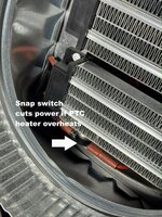


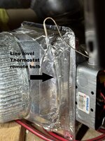
The science project...it's in a very space restriced area above out basement stair well.
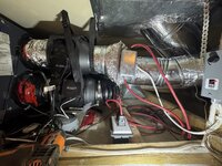
The four wall switches...two Zooz Zen 72s which control heater 1 and heater 2 on the left, and the two 0-10V dimmers that control ECM fan 1, and ECM fan 2. The old Venmar HRV control only signals if the defrost damper is closed...this is done by switching off the unit via a Fibaro smart implant (relay) connected to the HRV dry contacts. The Fibaro implant also connects the six temp probes that monitor the system and allow the Hubitat hub to manage defrost, heater settings, CFM settings etc.
Access to the system is via the panel at the top of the wall. Four cup magnets hold the cover in place. It's pretty much silent at 50, 60 and 75 CFM which is where the automation system runs it 95% of the time. CO2, Radon, and VOC sensors on each floor provide input to the Hubitat hub which dials in the ECM fans as appropriate. The hubitat hub also dials in variable length defrost durations depending on outside temps which get down to -35C here in winter.

Last edited:
I've been wanting to figure out a way to get differential air pressure readings into the house automation system so I could actively balance my HRV. I've modifed the HRV so instead of an old AC fan internally, there are now two ECM inline fans (one for fresh air, one for stale). I figure the "ultimate" method of varying CFM according to the air quality settings would be to continually ramp up or down on the fresh air CFM (based on what the home actually needs based on air quality), and then actively balance the stale air fan settings so air in precisely matches air out. This is what more expensive ERVs do, but they do it based on current sensing on the ECM fans...not actual pressure sensors!
I am not an electronics guru, so I needed to use off the shelf stuff, with little custom coding.
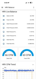
Using Home Assistant's "ESPHome" integration, two $9 ESP32 boards, and two Sensiron pressure sensors we get this. It definitely confirms that my ECM fan programming based on manual pressure testing (the HRV has balance ports to do this) was pretty darn close! Next step is to dynamically adjust the ECM fan motors (they are controlled by 0-10V) so the unit dynamically balances itself...
The other advantage of having live pressure data is to take guesswork out of changing out the MERV16 and charcoal filtration attached to this HRV to manage wild fire smoke. Having the unit dynamically balance itself means that as the filters load up, the fresh air fan can be ramped to deliver the target CFM, and stale air balanced accordingly.
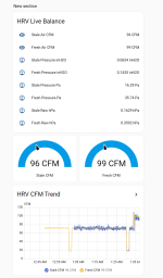
So these tiny sensors, the Sensirion SDP810-125Pa, (one for stale, and one for fresh air) is not cheap at around $40 each. 1/8" tubes go out to the HRV balancing ports.
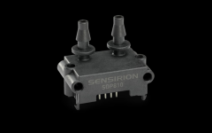
Each sensor is connected to one of these tiny boards (about $9)

..and that tiny board hosts the pressure sensor and talks to my Home Assitant box via WIFI.
The ESP Home integration in Home Assistant lets you custom program these ESP32 devices to host all kinds of sensors for temp, humidity, lidar, pressure etc. Super COOL!
I am not an electronics guru, so I needed to use off the shelf stuff, with little custom coding.
Using Home Assistant's "ESPHome" integration, two $9 ESP32 boards, and two Sensiron pressure sensors we get this. It definitely confirms that my ECM fan programming based on manual pressure testing (the HRV has balance ports to do this) was pretty darn close! Next step is to dynamically adjust the ECM fan motors (they are controlled by 0-10V) so the unit dynamically balances itself...
The other advantage of having live pressure data is to take guesswork out of changing out the MERV16 and charcoal filtration attached to this HRV to manage wild fire smoke. Having the unit dynamically balance itself means that as the filters load up, the fresh air fan can be ramped to deliver the target CFM, and stale air balanced accordingly.
So these tiny sensors, the Sensirion SDP810-125Pa, (one for stale, and one for fresh air) is not cheap at around $40 each. 1/8" tubes go out to the HRV balancing ports.
Each sensor is connected to one of these tiny boards (about $9)
..and that tiny board hosts the pressure sensor and talks to my Home Assitant box via WIFI.
The ESP Home integration in Home Assistant lets you custom program these ESP32 devices to host all kinds of sensors for temp, humidity, lidar, pressure etc. Super COOL!
Last edited:
fitter30
Well-known member
Ptc heaters draw max current at startup till it reaches set point then backs down. Look at your air temp vs setpoint. Air temp across any shape duct with or without a coil and or filter isn't the same cfm at all points. When balancing a system a traverse is done across the duct. Even with a diffuser plate it helps but not 100%. Averaging sensor might be betterway to go.Good question but I’d have to assume (and I’m no expert) but a failure to ground in the PTC element itself is all I could think of. I’ll do a post mortem…
Last edited:
Thanks for that input..it sounds like you know what you're talking aboutPtc heaters draw max current at startup till it reaches set point then backs down. Look at your air temp vs setpoint. Air temp across any shape duct with or without a coil and or filter isn't the same cfm at all points. When balancing a system a traverse is done across the duct. Even with a diffuser plate it helps but not 100%. Averaging sensor might be betterway to go.
The typical PTC behaviour is a bit of a question here for sure, as I'm essentially ignoring the PTC resistance ramp with temperature and just feeding the two heaters a calculated wattage based on the fresh air temp delta, and current operating CFM. I started with a baseline directly measuring current use by the heaters as I ramped the zWave dimmers from 0 to 99, then came up with an table/array that I could use in the programming. It works surprisingly well with the equation programmed into the automation hub. Given a temp delta and CFM, you can calculate the energy required to raise the air temp pretty precisely. That's what the automation hub is using to set the heater dimmers, and the sensor placed after the heaters pretty much confirms that the delivery target temp is pretty much spot on. You raise a good point though in that the PTC resistance at -30C vs +30C has to be quite different. That said...it works
I measure the temp of stale air going in and compare that to fresh air temp right after the heat exchange core. That way if the temp is set back at night, the HRV measures whatever the current interior outgoing (stale) air temp and uses that temp as the target for heated fresh air. Another (maybe obvious?) observation is that in our winter -25C temps, the HRV core is warmed up a lot during the defrost/recirc cycle. This means that right after the defrost cycle ends, delivered air temps are relatively warm, and drop quickly as the core loses energy. That temp delta therefore changes literally by the minute, and the heater wattage is ramped dynamically by the Hubitat hub.
fitter30
Well-known member
If u got away from rheostats to 0-10 volts could write a program and make changes easily.Thanks for that input..it sounds like you know what you're talking about
The typical PTC behaviour is a bit of a question here for sure, as I'm essentially ignoring the PTC resistance ramp with temperature and just feeding the two heaters a calculated wattage based on the fresh air temp delta, and current operating CFM. I started with a baseline directly measuring current use by the heaters as I ramped the zWave dimmers from 0 to 99, then came up with an table/array that I could use in the programming. It works surprisingly well with the equation programmed into the automation hub. Given a temp delta and CFM, you can calculate the energy required to raise the air temp pretty precisely. That's what the automation hub is using to set the heater dimmers, and the sensor placed after the heaters pretty much confirms that the delivery target temp is pretty much spot on. You raise a good point though in that the PTC resistance at -30C vs +30C has to be quite different. That said...it works
I measure the temp of stale air going in and compare that to fresh air temp right after the heat exchange core. That way if the temp is set back at night, the HRV measures whatever the current interior outgoing (stale) air temp and uses that temp as the target for heated fresh air. Another (maybe obvious?) observation is that in our winter -25C temps, the HRV core is warmed up a lot during the defrost/recirc cycle. This means that right after the defrost cycle ends, delivered air temps are relatively warm, and drop quickly as the core loses energy. That temp delta therefore changes literally by the minute, and the heater wattage is ramped dynamically by the Hubitat hub.
The two ECM fans are 0-10V, but the heaters each have their own Zooz 700 series "dimmer" which uses triac dimming and adjust from 0-99 digitally. So dumb heaters, but pretty smart dimmersIf u got away from rheostats to 0-10 volts could write a program and make changes easily.
Every time the supply air temp changes, the automation hub calculates the dimmer setting using this equation. The CFM variable is set to 50,60,75,90,100 or 110 CFM depending on what IAQ sensors are averaging inside the house.
Dimmer setting = .122 * (((CFM Variable x 1.08 x (Stale Air Exhaust Temp - Fresh Air temp))/3.41)/2) + 16
The filter system is proving super effective as we are seeing literal fire smoke and ash falling today. Combined with 38C temps, it’s looking honestly apocalyptic outside …

Inside, zero smoke smell and PM2.5s are pretty low too.

And new for this year, electronic differential pressure sensors (Sensirion SDP810-125Pa differential-pressure sensors) using $9 ESP32 boards (WiFi) programmed using ESP Home in Home Assistant. I’ll be adding some code so that the HRV system will auto balance as the interior IAQ sensors drive the system ramping between 50 and 110 CFM
These are about $30 each. Tubing runs to the HRV balance ports on the HrV door.
Inside, zero smoke smell and PM2.5s are pretty low too.
And new for this year, electronic differential pressure sensors (Sensirion SDP810-125Pa differential-pressure sensors) using $9 ESP32 boards (WiFi) programmed using ESP Home in Home Assistant. I’ll be adding some code so that the HRV system will auto balance as the interior IAQ sensors drive the system ramping between 50 and 110 CFM
These are about $30 each. Tubing runs to the HRV balance ports on the HrV door.
Attachments

Last edited:
This is the unit measuring pressure at the balancing ports and sending CFM data to Home Assistant. About $120 all in…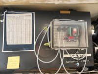
A 12V power buck is taking voltage down to 5V for each EsP32 board. Each board hosts a sensor and has its own IP address on the WIfI network. I could have had both Senserion sensors on one ESP32, but the boards are literally $7 each…

A 12V power buck is taking voltage down to 5V for each EsP32 board. Each board hosts a sensor and has its own IP address on the WIfI network. I could have had both Senserion sensors on one ESP32, but the boards are literally $7 each…