To avoid these ads, REGISTER NOW!

The Aerodrome Studio - Machine_Punk

OP
M

machine_punk

Well-known member
Joined
May 14, 2011
Messages
2,540
Location
Napa Valley, California
Drilling Holes

I spent the afternoon in the shop...mostly drilling holes and finishing aluminum corner brackets.

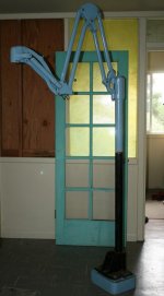
I've been using the camera bracket I built earlier...
View media item 11682
to photograph things out in the studio. Here, the camera is 'looking over my shoulder,' which THEORETICALLY means you can see what I see, as I work. I set the camera on 'delay' and then start a function (in this case, my function is 'standing in front of the drill press') and let the camera take a picture in a few seconds. I'm not sure the action shots add anything to the thread, but it's fun.
View media item 13302
Here, I am pointing at the center mark I made for the main hole in the Fantastic Light Brackets. I made the mark for this center mark on the original paper template for these pieces and punched the center mark before I even cut the part out. It really saved a lot of trouble in figuring out where I should drill the hole later...
View media item 13303

I've been kinda nervous about drilling this hole. It is the primary function of these plates...to receive the mounting tube of my two dental lights. If these holes are drilled incorrectly, I have a LOT of machining to redo. Here is an earlier test with a scrap piece. The hole is 1-11/16ths, so I had to special order the hole saw just for these brackets...
View media item 12625
And here is my original design sketch, showing how the mounting tube will fit through these two plates...
View media item 12628
View media item 12626
Any time I want a hole accurately placed, I use a process similar to what many machinists use to accurately drill a hole. I mark the location with a fine-point marker, use a ***** punch to punch a center mark (easier to see where it is placed than a center punch), punch a center mark with a center punch, drill a center hole with a center drill (see picture below), then drill with the final drill (this is aluminum...I don't usually find I need to step up slowly through the different drill sizes)...
View media item 13304
This is one of those 'action shots.' I am drilling the hole with a hole saw. I have both the plates clamped together, so I know the hole is exactly in the same place on each plate...
View media item 13305
Viola'! Two 1-11/16th-inch holes, exactly where I want them...
View media item 13306
Here is test piece I created. A regular 'jobber length drill bit deflects too much to do this, so I tried it with my center hole drills. I'm trying to put a slot in the aluminum, like the punched slot in the lower picture. I'm going to have to figure something else out--these are really tough to do, require a great deal of hand work, and look like I cut them with a chain saw...
View media item 13307
View media item 13090
Drilling two, overlapping holes just isn't as easy as you think it could be. I'd much rather get a punch made for this slot size...I'd like to get a punch and die made for these standard rivet squeezers...I think they would have enough pressure for the 0.125" aluminum I am trying to put these slots in (they squeeze with 6,000 pounds of pressure)...
View media item 11624
I worked on a couple of other little test pieces, but I didn't get any pictures.
 
Last edited:
To avoid these ads, REGISTER NOW!

PSYKO_Inc

Well-known member
Joined
Oct 23, 2010
Messages
565
Location
Fairfield, CA
Wow, can't believe I didn't see this thread till now. Love the "dental light" idea, and have often considered something similar for my garage; hang it in the center of the roof and put light right where I need it while under the hood of a car. Also really digging the rack mount idea. I've got a background in IT, radio equipment, and audio (started in the AF as a network guy, cross-trained to Ground Radio which also handles PA equipment and Giant Voice setups) and own a fair amount of rackmount gear. BTW, in response to an earlier post, I was stationed at Sheppard as well, '04-'07 :D As for cutting the slots, why not just cut them wider so the holes don't overlap? Or since it's going to be hidden by a washer anyway, just drill a slightly bigger diameter hole than you need in lieu of the slot? Alternately, you could look into Greenlee punches, usually a little on the expensive side but would make life a lot easier. :beer:
 
OP
M

machine_punk

Well-known member
Joined
May 14, 2011
Messages
2,540
Location
Napa Valley, California
Hey neighbor! Thanks for the kind words. I meant to tell you the next time I heard from you that I do seem to remember seeing your truck around Fairfield. Of course, that was before I knew you were another GJ'er.

I've pretty much decided on the second option...drilling a little bit larger hole, then letting the washer cover it. Even if I could find a relatively simple way to drill the slots, they are still a LOT of manual work--and I will literally be cutting dozens of these slots. I think I'll hang my pride up and just go with the over-sized holes for making adjustments.

My original reason for trying to make the slots was simply that it was the way I've seen it done on the professional gear. It didn't even occur to me that there might be another way. I'd still prefer to come up with some sort of punch...but I'm not going to stress about it.

Anyway, thanks for the information and the kind words...I'll be updating this as I continue to build new things. I'm thinking I will have to get a coat of paint on the walls before I go too much further. I suppose I better go find a few paint chips and pick my 'official' garage colors.
 

Tripp P.

Well-known member
Joined
Jan 6, 2011
Messages
117
Location
G.R. Michigan
Just checked out your thread. Really like the rivet work. Very interested in seeing the lights finished. I think your going to really like your color choice. My walls are also a very pale yellow. Its bright enough to still reflect a lot of light.:thumbup:
 
OP
M

machine_punk

Well-known member
Joined
May 14, 2011
Messages
2,540
Location
Napa Valley, California
Just checked out your thread. Really like the rivet work. Very interested in seeing the lights finished. I think your going to really like your color choice. My walls are also a very pale yellow. Its bright enough to still reflect a lot of light.:thumbup:

Thanks for the kind words. I look forward to finishing these light brackets too...then I can move on to my next project, which is ________ (well, you'll just have to stay posted...I have a long list of projects coming up and I think I know which one is next.)

I remember thumbing through the thread of your garage a while ago...lotsa neat ideas there. I'm sure you are pleased to be working in such a well-thought-out shop!
 

JSBriggs

Well-known member
Joined
May 10, 2009
Messages
1,041
Location
Auburn CA
Its funny, I picked up this older dental armature this summer, thinking ill turn it into a floor lamp for the house. I thought it would be too huge and heavy for the shop. I might need to renegotiate with my wife to get it back.

-Jeff
 

Attachments

  • IMG_6888a.JPG
    IMG_6888a.JPG
    43.6 KB · Views: 348
OP
M

machine_punk

Well-known member
Joined
May 14, 2011
Messages
2,540
Location
Napa Valley, California
Its funny, I picked up this older dental armature this summer, thinking ill turn it into a floor lamp for the house. I thought it would be too huge and heavy for the shop. I might need to renegotiate with my wife to get it back.

-Jeff

I agree, Jeff...that is too huge and heavy for the shop. In fact, it's too big for the house, too...since you are so close, I'd be happy to come out with my big van and haul that off for you! Just trying to help, you know...that's the sort of guy I am.

Seriously, though...that is way cool. Now you've got the wheels spinning...what sort of lamp would I build on that? I think if you could get an old Dazor lamp head on eBay (something where the arm is damage, but the head is salvageable), that would look cool. With that size, you could even go with a porcelain covered metal reflector and mount one of those explosion-proof fixtures underneath, or...., or....
 

JSBriggs

Well-known member
Joined
May 10, 2009
Messages
1,041
Location
Auburn CA
I was thinking of the Ikea Ottava old gas lamp look for a lamp, but I need to keep looking around a bit if it will end up in the shop. I've already got an old clamp on Dazor for my desk in the office of the shop. They are cool.

In other news, have you considered using an end mill and a cross slide vise in your drill press to ovalize the holes. I wouldnt do it with steel, but Aluminum shouldnt side load it too much.

-Jeff
 
OP
M

machine_punk

Well-known member
Joined
May 14, 2011
Messages
2,540
Location
Napa Valley, California
I was thinking of the Ikea Ottava old gas lamp look for a lamp, but I need to keep looking around a bit if it will end up in the shop. I've already got an old clamp on Dazor for my desk in the office of the shop. They are cool.

In other news, have you considered using an end mill and a cross slide vise in your drill press to ovalize the holes. I wouldnt do it with steel, but Aluminum shouldnt side load it too much.

-Jeff

That's not a bad thought, using and end mill in the drill press. The reality is that I have to cut dozens of these, eventually, and I don't really want to put that much hand work into the slots. So far, the rack I am almost done with is 4 rack-spaces wide and 20 rack-spaces tall...so, theoretically, I could have up to 80 tool boards to punch 4 holes in each. Now, I have discovered that a single-rack-space tool board is essentially worthless...there are very few sets of tools which would fit on a tool board which is only one rack-space in size. I certainly won't need 80 tool boards, but,even if I had just 25 tool boards to make, that would be 100 slots to cut by hand. Each of the dental light brackets alone will have up to 18 slots each, through 1/4" material. Not to mention the fact I plan to put this rack rail material on several other surfaces in the shop. I need to find a better way than 'hand fabricating' these slots. I think using a little bit larger hole will be adequate for now.

I was looking online here at a place which will custom make punches for me (I would have them made for my pneumatic rivet squeezers). I may even play with making my own punch...how hard could that be?...
http://shop.z-tech.com/

One other thought I have is using the router with a plunge bit. Make a template for the slots and clamp the metal in place. Hmmmmmmmmm...
 
OP
M

machine_punk

Well-known member
Joined
May 14, 2011
Messages
2,540
Location
Napa Valley, California
I only got about 3 hours out in the studio today. Even though I didn't a whole lot done, both the boys (my stepsons, ages 12 & 15) came out to the studio for a little while and worked with me. The youngest one, who usually could care less about tools, spent some time with the air angle grinder and surface conditioner disc, getting the RTR (Reconfigurable Tool Rack) ready for assembly. I did my fair share of surface conditioning too, but also started to get ready for riveting the RTR together.

First, I got a couple of things in the mail yesterday. Two 'rivet fans' (tools used to evenly space rows of rivets) and a pound of rivets.
View media item 13358
The second pound of rivets, the ones I will use in the Fantastic Light Brackets for the dental lights, arrived today...
View media item 13360
View media item 13065
So, here's what we're building, a rack to hold rack rails to hold custom, moveable tool boards...
View media item 13010
And my small test piece, showing all the different parts...
View media item 13077
Speaking of test pieces, here is the test piece i built today. I marked the position of the rivets on each end, then used the new rivet fans to lay out the rest of the rivet positions. (For those of you who do this for a living, YES, I know these rivets are too close...this is a test piece and I don't want to waste a lot of material, just to set up a machine.)
View media item 13361
The test piece above is made of the same thickness of materials for this test piece I built quite a while ago, as a 'proof of concept' piece...
View media item 13025
I was showing my son how I was going to put all of these pieces together, including the corner brackets. So, he asks me, "Dad," (because he calls me 'dad,') he asks, "Dad, how are you going to get the riveter up into that corner rivet?" I says, "Son," (because I call him 'son,') I says, "Son, the same way I am going to get to the rest of them, just put the rivet gun on them. (while I am picturing this rivet GUN...)
View media item 11623
He says, "OH, I thought you were going to use the c-shaped thingy." (He's picturing the rivet SQUEEZERS that I have...)
View media item 11624
To which I say, "DOH," WHY DIDN'T I THINK OF THAT???. Fortunately, I haven't assembled the frame yet, and I can still use the rivet squeezer (so much easier and less chance of getting smileys (misplaced rivet gun set marks) on the frame material. As soon as he mentioned the pneumatic squeezer, I knew that they would still have the enough reach to get the rivets way up in the corner. I also knew it was the right answer for this project. (As a manager, I completely recognize that I don't always have the right answer, but I definitely recognize the right answer, when I see it!)

So, that is the reason for the new test piece, which uses the same aluminum angle and two pieces of the same thickness as the corner brackets I plan to use. The thing with the rivet squeezers is they can squeeze rivets exactly the same way all day long, but they require a fairly intense setup process to get the rivets squeezed correctly.

I usually find that I can get the rivet squeezer set correctly within about 5 squeezes. You just keep swapping out different depths of 'rivet sets' (the little inverse-rivet-head-shaped anvils used to engage the rivet while squeezing) and the shims (or, in lieu of shims, #10 washers). These rivet sets come standard with a 3/16" pin to fit in the 'jaws' of the rivet squeezer.

So, once I prepped the test-piece parts, clamped them together, layed out and drilled the holes, deburred the holes, and temporarily clamped it together with Clecos, (WHEW. using solid rivets is like painting...all the work is in the preparation. Once you get to actually bucking rivets, it is fairly anticlimactic. I was ready to set up the rivets squeezer for the specific materials and rivets I was going to use.

Or was I? As I build up my supply of rivets, I tend to buy the 'dash 16' length (length is measured in 16ths, so these are 1" long), so I can simply cut them down to the size I need, if I just need a few. If I need more than a 'few,' I go ahead and buy a whole pound of them, to build up my stock. Since the only rivets I had in the 6/32nds size, which were long enough, I was going to have to cut down some rivets.

Here, you see me holding the test piece of the correct thickness, with a 1' rivet in one of the holes through the material, with the rivet 'length gauge' I built a few weeks before. (Set for 1.5x the diameter of each rivet size I use routinely. I didn't come up with this idea...but I did actually build this gauge from scrap materials.) So, now I can mark the rivets and cut them to the correct length to maximize their strength...
View media item 13368
Here is the same shot, with the rivet length gauge out of the way. You see where I have marked the rivet for the correct length for this application.
View media item 13369
I cut down rivets by simply using the belt sander. It's tough to hold onto them while you grind off the end, even if you use a pair of pliers to hold them. I had a brilliant idea today for a tool which would help me grind the rivets to the correct length on the sander. I needed something which would securely hold the rivets perpendicular to the sander belt. Here's what I came up with, from my scrap bin. A heavy duty piece of aluminum angle, a 1/4" thick additional piece of aluminum plate, riveted together and a hole drilled through to hold the rivet perpendicular to the sanding belt. I know that this isn't 'perfect,' but it is a just a 'test piece' too...
View media item 13370
View media item 13371
View media item 13372
View media item 13374
And here is one 'original length' rivet, surround by seven others, which are now the correct length for this test piece...
View media item 13375
The rivet grinding bracket turned out to be great at holding rivets while you grind them to length. It also excels at burning the snot out of the tip of your thumb, as the rivet heats up from the friction of sanding. Since this sanding bracket worked out so well, I may have to build one which works for all the rivet sizes I use routinely (3/32", 4/32", 5/32" and 6/32").

I must be getting better at setting up the rivet squeezers. I prepped a test piece with seven holes. I usually take about 4-5 tries to get the squeezer set up. This time, I actually got it on first try. I went ahead and squeezed two more rivets just to make sure (and, because using the rivets squeezer is so much fun! It's almost like magic) I left the other four holes to practice again right before assembling the frame...
View media item 13377
And some pics of the squeezed rivets...
View media item 13376
View media item 13384
View media item 13383
And a quick last pic of my previous proof-of-concept piece, today's rivet squeezer test piece, and the rivet grinding tool I built today...
View media item 13385
Happy Thanksgiving to everyone! I'll be working 4 hours tomorrow morning, then heading out to spend time with the wife's family, in the Sacramento area. I am thankful for this wonderful place to learn and share, called Garage Journal.
 
Last edited:
OP
M

machine_punk

Well-known member
Joined
May 14, 2011
Messages
2,540
Location
Napa Valley, California
Since the whole family was home today, I didn't spend a lot of time out in the garage. We did have a couple of errands to do, so we did go out, but NOT to shop for Black Friday. Everyone else was keeping themselves entertained later this afternoon, so I got a couple of hours out in the studio.

I've got two projects up in the air right now, the Reconfigurable Tool Rack and the Fantastic Light Brackets for the dental lights. They actually work together, which you will see very soon. In the last few weeks, I've been kinda spending my time equally on both projects.

In the last few days, I've just been focusing on completing the Reconfigurable Tool Rack. I want to have closure on at least one project, then focus on the light brackets. I picked the tool rack to finish first, because I am at the point I have everything I need to complete it. My list of items to complete on that project is tiny now:
- Drill holes for the rivets (in the brackets and the frame)
- Surface conditioning on all the parts (I actually have a fair amount of this done. I don't plan to paint this project, I want to see the natural aluminum finish. I figured out that I should have waited for the ALL of the fabrication to be completed, before doing any surface conditioning...you're just wasting your time if the fabrication isn't completed)
- Assemble the frame
- Mount the rack rails on the frame
- Mount the Reconfigurable Tool Rack on the wall (actually, I will mount unistrut horizontally on the wall, then mount the tool rack on the unistrut). (And that makes me ask myself, "Do I really want to mount anything on the wall, BEFORE I get the holes patched and the walls painted?")

So, I did get a little time in the studio this evening. I concentrated on drilling holes. Before I could drill holes, though, I began to question whether I wanted to use more rivets on each joint. The test piece I built is incredibly strong, but I knew that the standards for rivet spacing would allow me to place the rivets closer. The question was whether or not it would actually fit on the brackets I have already cut out (lessons learned, which will be applied to building later projects. I cut these brackets out a couple of months ago, LONG before I even knew which size of rivet I was going to use. In fact, I cut the brackets to fit the material I had, instead of designing a bracket, then finding enough material to make them.

So, you will remember that you can space rivets in a line between 4 and 5 rivet diameters apart for maximum strength. With 'dash 6' rivets (6/32nds"), that gives us between 24/32nds" (3/4") and 30/32nds" (15/16ths"). I had already designed the brackets for 1" spacing (not too far off 15/16ths, so no need to worry too much). I wanted to see if I could add another rivet, for a bit more strength in the joint. So, I looked at 3/4" spacing. I built a test piece with the extra rivets and placed it next to the proof-of-concept piece to check it out...
View media item 13413
While I don't mind the look of the extra couple of rivets, the reality is that the extra rivet that matters just ends up on a joint in the material, so it really wouldn't add any strength. So, back to 5 rivets in the bracket, instead of 7. I'm glad I built a test piece...I would have always wondered...or gone ahead and drilled the different holes and cursed at myself after ruining 10 brackets.

I eventually need to drill the holes all the way through the front corner brackets, the frame rail, and the rear corner brackets. The question I had to answer today was 'in which order' should I drill the holes (See the top, left object in the first picture below...this is the proof-of-concept piece for the corner brackets. This piece was easy to drill--I could take everything to the drill press):

OPTION 1: clamp an entire corner together at the same time and drill all the way through all three pieces. Well, until I grow about four more arms, that's going to be tough. The corner clamp I have is for welding and it would not work for this application. It would also be very difficult to get all the pieces aligned and into the drill press at the same time (I don't have a lot of open space in my shop yet). While it would be fabulous to get all three pieces drilled at the same time, it is would be tough to get, and keep, all of these pieces lined up at the same time.

OPTION 2: Drill the front and the back corner brackets at the same time, then place them on the frame in the correct position and drill the frame. The problem I have with this option is that while it makes sure the front and rear bracket are drilled exactly identical, it won't necessarily mean that the holes in the frame will be properly aligned with the front and back plates.

OPTION 3: Drill just the front corner bracket pieces in the drill press. Then, position the front corner brackets correctly and use them as a template for the drilling the frame. Then, use the front bracket and the frame as a template for the rear brackets. This allows me to drill the front brackets very accurately on the drill press (and makes a 'pretty' front plate) and allows the frame and rear bracket holes to be drilled in alignment with the perfect front plates.
View media item 13385

I chose option three. So, on to drilling the holes in the front brackets...

Here are all the little bits I ended up with after considering all of my options. The original proof-of-concept piece, test pieces for both 5-rivet and 7-rivet options, and a template drilled to make marks for both options...
View media item 13414
My process for accurately placing holes in metal is similar to what machinists use (from what I have read):
- Mark the holes with a fine marker
- Punch with a ***** punch (a finer point and easier to see where you are marking).
- Punch with a center punch (closer to the angle of the point of a drill bit)
- Drill a center hole with a center drill.
- Drill to final hole size (smaller pilot holes don't seem to be necessary in aluminum).

That's a lot of steps, but I am getting much better at making straight lines of evenly-spaced holes in which to insert rivets. It is a little time intensive, though. I calculate 66 holes I drilled tonight, with 5 steps per hole so far.

View media item 13415
View media item 13416
Then there is the deburring the holes...and you get to do that to both sides, so deburring 132 times for 66 holes. Here is the back of the bracket, where the drill punched through. I backed it up with a piece of wood, but there is still a fair amount of deburring to do. The bracket in front has been deburred (and, in fact, shows just a touch of contersinking). The bracket in the back still needs to be deburred. You also see the tip of the deburring tool I use for holes. Like most of the bits used in the aircraft industry, this one is attached to the deburring handle by a 1/4-28 thread.
View media item 13417
Even the front side of the bracket develops a little ridge around the hole, which also needs deburring...
View media item 13419
An overall picture of some of the deburring tools I use. The dogleg deburring tool I use for holes and the edge deburring tool I use.
View media item 13418
A LOT of holes, which have gone through a LOT of steps to get to this point...
View media item 13420
This process of building my own shop fixtures is doing exactly what I wanted. If you remember, I am modeling my learning experience after the classic apprenticeship of wood joiners, who first have to build their own tool chests, bench, and other items, BEFORE the master will let him begin to work on any client's project.

I've really learned a lot, while building these projects for my shop. I've intentionally started with larger projects, which didn't need quite the accuracy I hope to be able to produce as I continue to practice. The big lessons from today...there is a lot of planning and math on paper before you should be cutting anything. Today I had a choice of using 5 or 7 rivets per corner bracket. I really shouldn't have cut any metal, before I had that figured out.

Anyway, that's all for now. I'll post more, when I get more time in the studio.
 
Last edited:

motorheadsdiygarage

Well-known member
Joined
May 4, 2011
Messages
109
Location
Near Montreal
I've been in the aircraft maintenance and repair business for the last 25 years. I see you have the lust for riveted assembly. During the drilling and filling of millions of holes ,you find ways to work smart instead of hard. After all, your wrists, elbows and shoulders will pay the price in the end (e.g. carpel tunnel syndrome and tendonitis).

Aviation tools to make your projects easier.

Here's the link: http://www.yardstore.com

(I can't remember but I think aluminum dust has been linked to Alziemers......lol. Use a dust mask when sanding.)

By the way very nice designs.
 
Last edited:
OP
M

machine_punk

Well-known member
Joined
May 14, 2011
Messages
2,540
Location
Napa Valley, California
I've been in the aircraft maintenance and repair business for the last 25 years. I see you have the lust for riveted assembly. During the drilling and filling of millions of holes ,you find ways to work smart instead of hard. After all, your wrists, elbows and shoulders will pay the price in the end (e.g. carpel tunnel syndrome and tendonitis).

Aviation tools to make your projects easier.

Here's the link: http://www.yardstore.com

(I can't remember but I think aluminum dust has been linked to Alziemers......lol. Use a dust mask when sanding.)

By the way very nice designs.

Thanks for the kind words!

Were there any specific aviation tools you were thinking about that you don't see me using? Brown Tool is my preferred provider (if they sell it). The owner built the company from the back of his pickup truck to the huge distributor they are now. They try very hard to provide a US-made version of everything, so you can make the choice of price vs. country of origin. I also generally use Aircraft Spruce for my rivets and hardware. A little on the expensive side, but the supplies I tend to buy are aircraft rated.

Brown Tool Company...
http://www.browntool.com/

Aircraft Spruce...
http://www.aircraftspruce.com/

While I have looked at the Material Safety Data Sheet for aluminum, and there are no hazards listed, I do generally wear an N95 dust mask (see earlier posts) when I am sanding or grinding aluminum. After seeing what the dust mask has trapped (it is gray after a few hours), I am glad I chose to wear them.
 
Last edited:

EdT

Well-known member
Joined
Sep 21, 2010
Messages
1,104
Location
North Georgia
I'd sure spend an evening making a fixture to do the corner brackets. since you are stuck with hand layout and machining, they may not be exactly what you want, but there is a very good chance they will al be the same which helps. I think the best bet for getting all the holes to line up is to drill the corner plates and use them as drill guides for the angles. Drill a couple of holes, put in some clecos (or rivets if you're brave) and then drill the rest and finish riveting
For the slots, I think the router is worth a try, but be careful. If you can find a down spiral bit, it will push the chips away from you which would make the whole operation less unpleasant. Again, you will definitely need a good fixture. No freehand here. BTW, regular milling cutters should work in the router, but watch out that you get a shank size that fits your router. It would also be good to run the router at a lower speed than you would use for wood.
 
OP
M

machine_punk

Well-known member
Joined
May 14, 2011
Messages
2,540
Location
Napa Valley, California
1. I'd sure spend an evening making a fixture to do the corner brackets. since you are stuck with hand layout and machining, they may not be exactly what you want, but there is a very good chance they will all be the same which helps.

2. I think the best bet for getting all the holes to line up is to drill the corner plates and use them as drill guides for the angles. Drill a couple of holes, put in some clecos (or rivets if you're brave) and then drill the rest and finish riveting

3. For the slots, I think the router is worth a try, but be careful. If you can find a down spiral bit, it will push the chips away from you which would make the whole operation less unpleasant. Again, you will definitely need a good fixture. No freehand here. BTW, regular milling cutters should work in the router, but watch out that you get a shank size that fits your router. It would also be good to run the router at a lower speed than you would use for wood.


Thanks for the ideas...I appreciate you taking the time to look at what I am doing and make some valuable suggestions.

1. I actually have all the corner brackets built now. Of course, I do plan to do more of these Reconfigurable Tool Racks...and a fixture will help. I kinda did this 'the hard way' this time because I wanted to get to the bare roots of fabricating. I think that in the future, I'll machine repetitive parts like this with the router and a template-following bit.

I had a bit of a 'DOH' moment, as I look back at the "T" brackets...I made the corner very sharp...it should have been rounded (drill a hole for the corner, then cut the straight lines up to that rounded corner). The current bracket design puts a serious stress riser at that corner, which would be a problem, if the whole frame wasn't so over-designed to start with.

2. That's pretty much what I planned for drilling those corners.

3. If I used a router, I was thinking of a down-spiral bit, but I hadn't even considered a small milling bit (my router has a 1/4" collet and the slots are right at 1/4" in width). That just might work. That is definitely something worth making the template for...I'll be building a fair number of these tool boards.

Thanks for the ideas!
 

Red Leader

Well-known member
Joined
May 15, 2011
Messages
2,688
Location
Denver, CO
Machine Punk,

I must have missed it earlier in the thread (and I'm not good at finding things:)) but what are you currently working on assembling (as in, end goal)?

-Dave
 
To avoid these ads, REGISTER NOW!
OP
M

machine_punk

Well-known member
Joined
May 14, 2011
Messages
2,540
Location
Napa Valley, California
I can understand your confusion...I am working on TWO major projects right now--and neither one of them are like anything I've seen before...

1. The Reconfigurable Tool Rack. Here is what the frame will look like 'life size,' but not 'finished.' Here you see it layed out on the back patio. Eventually, it will be attached to the wall and function like a pegboard, only completely custom and completely reconfigurable. On the left, you see the wood spacers I will use to lay out the rack evenly. The second bay of the rack has the rack rail (pre-drilled and tapped for 10-32 screws) laid in place with a couple of blank tool boards sitting at an angle. The other two bays are empty for now...
View media item 13008
And this is a test piece with all of the components (an aluminum angle framework which supports standard, industrial, pre-threaded rack rails, which will allow me to attach moveable, custom tool boards to the framework) This system allows me to have many miniature tool boards for my tools, but still move them around, as my needs change. In this sample piece, you see a few 'rivet sets' and a few spacers on a custom tool board...
View media item 13079
View media item 13080
View media item 13077
Eventually, pretty much every vertical surface in my shop will be covered by these rack units, which will allow me to store the tools I use close to where I use them.

2. My second major project at this time is to build brackets for mounting my two new (to me) dental lights...
View media item 12624
The design for my light brackets is based on the parabolas found in the reflector lenses of the lights...
View media item 12716
View media item 12720
These four, intersecting parabolas will be attached with solid rivets and small aluminum angle...
View media item 13066
While they are two different projects, they actually work together, which you will see soon.

I am actually not too far from completion of the Reconfigurable Tool Rack. I probably have dozens of hours left in the light brackets.

Of course, I have a few major projects planned after that, including building custom tool boards for most of my tools. Then, I plan to build a muffler for my air compressor. An aircraft-inspired reconfigurable bench-power-tool table. An aircraft-inspired tool, parts and material storage unit. A custom work holder. An aircraft-like workbench. And on and on...until I am happy with The Aerodrome Studio and I can begin to build aircraft-like furniture. My overall goal right now is to learn the skills of my craft, just like a wood joining apprentice did, while I am building my workshop from scratch. Then, I will begin to work on the artistic projects I actually want to build.
 
Last edited:

twokidsnosleep

Well-known member
Joined
Aug 21, 2010
Messages
65
Location
Burnaby BC
I have tossed half a dozen of this style P&C lights from my old office, never even thinking of using them at home.
Recently crapped out two cheap workspace lights as the 500W bulbs blow like a cheap....well you know. So here I am searching for new shop task lighting and you show me something I used every day at work.
Shows you how blindsided I can be.
Great build!
 
OP
M

machine_punk

Well-known member
Joined
May 14, 2011
Messages
2,540
Location
Napa Valley, California
Reconfigurable Tool Rack Assembly

I didn't get nearly as much done today as I hoped. I had pretty much all day to work in the shop, but I didn't really get started until about noon. Since I don't have enough room to work on the Reconfigurable Tool Rack in the garage right now, I had to move a bunch of tools and materials out to the back patio to work (it was in the mid 50's and sunny...I was able to work in jeans and a t-shirt, until the sun went down).

I didn't get as many pictures as I usually do, but I have a few.

My goal today was to get the framework for the Reconfigurable Tool Rack riveted together. Before I could even start, I had to cut a bunch of rivets to length and deburr them...62 rivets, plus a few spares, 'just in case.' What I realized (later), is that 50 of those rivets needed to be length I cut them, and the other dozen needed to be a little shorter (since they would be put in holes where there was only one bracket, instead of a bracket on the front and on the back). You'll see a picture of that in a minute.

Here is where I started this morning. The corner which needs to be joined and a short stack of corner brackets, which will be riveted on to complete the joint. If you look back at my last post, the corner brackets which will be on the top are already drilled...I did that on the drill press, to ensure they were lined up and nicer looking. The corner bracket on the top of this stack will actually go on the back of the joint (behind the front corner bracket and the frame). I tried a couple of different processes, until I realized it was best to go ahead and drill the back brackets on the drill press too, using the front brackets as a template.
View media item 13495
Note to self: Working on the ground STINKS! I've really got to get the garage cleaned out and get some room in my metal studio. Working on projects like this at bench height will be much nicer than crawling around on the patio.

Here are the first two corners, completed. It took WAY longer to get these done than I thought it would. The biggest issue is keeping everything lined up while you drill (it ended up being 'measure 20 times, drill once,' just because I didn't want to make any mistakes I couldn't recover from). I think I need about 30 more clamps too...
View media item 13496
Just an overview of the two completed corner joints...
View media item 13497
Dark was sneaking up on me by this time, but I continued with one more joint. I had all the measuring done, so I wanted to go ahead and drill the holes (riveting is actually nothing after that...the pneumatic rivet squeezer was set up and it can press the same rivet setup all day long, once you get the holes drilled accurately). These center joints (I call them 'T' joints, as opposed to the easier corner joints) are much more complex.

Here is a pic of the top horizontal frame member, one of the middle vertical members, the 'front' plate for the T-joints, and the back plate for T-joints...
View media item 13085
Here you can see how I chose to cut a relief in the vertical member, to allow the 'T' to pass through...
View media item 13084
Here are a couple of pics of the T-joints after a few rivets have been placed. Here is an angle from the front. Not all the rivets are in place...and you will see why in a moment...
View media item 13500
Here is a shot of the back. Here you can see how the back plate provides rigidity in the opposite direction...
View media item 13498
Here is another shot of the front. The CIRCLE is pointing out an epic fail in planning. The rivet won't actually fit in that hole...so I will have to remove the vertical member (drill out the rivets), place this rivet, then cut a relief in the vertical member to allow room for the rivet). This problem will be designed out in future versions. (did you notice that I made the circles in the colors my shop will be painted? Fudgescicle brown and pale yellow). The arrow points to the back plate, which covers the opposite direction as the front...
View media item 13503
Here is a pic of the back. I have circled the same hole (epic fail), just so you can orient yourself to the back of the piece. Here, the arrow points to one of the two holes in each T brace which will have to have shorter rivets, since the rivet only needs to go through one cover plate and the frame, instead of two cover plates and the frame...
View media item 13502
While I am pointing out things I might do differently in the future, here is another. This corner is what is called a stress riser. Stress risers are defects or design elements which could cause a crack as the part is repetitively stressed. This corner wouldn't work in an airplane. I've completely over-designed this joint, so I don't anticipate a problem, but it would have been MUCH better to drill a hole at this corner, then bring the flat edges up to that hole (i.e. NOT squared off, but rounded off). I don't think it will be a problem here, but I will definitely design this part differently in the future...
View media item 13504
 
Last edited:
OP
M

machine_punk

Well-known member
Joined
May 14, 2011
Messages
2,540
Location
Napa Valley, California
I got about three hours in the metal studio this afternoon. It blows me away just how long it can take to do some of this fabrication. Of course, this afternoon I had to do some 're-work.'

I drilled out the rivets from a bracket (new to me...had to figure out the right way to do that). I didn't realize until the end that I didn't get any pics of that. The basic principle is to put a center punch in the center of the solid rivet head, then drill just far enough to release the head of the rivet, then use a punch to drive the rivet body through the hole. It turned out being easier than I thought it would be.

As part of that re-work, I moved the bracket as far as I could (about 1/4 inch) closer to where I originally planned to have it. The last time I was drilling and riveting brackets, I should have just quit when I was ahead...you know how you get close to the end of the time you have and you just want to get 'one more thing' done and so you rush it a bit and it always comes back to bite you? Well, I wish I had stuck to my original plan.

So, here is one of the new joints, all riveted and ready to use. I am still building an aluminum frame to hold standard equipment rack rails, which will have mini tool boards on them for specific sets of tools. This is one of the center joints, instead of one of the corner joints. Here, I used a 'T' plate on the front and a triangular plate on the back...
View media item 13709
This picture looks a bit odd, because the frame is actually sitting on its short end, instead of how it will be mounted on the wall, with the long side across the top and bottom. So, in this picture, the frame is actually in it's final orientation, but the camera was sideways, when I took the picture...
View media item 13710
View media item 13711
So, it doesn't feel like I got a lot done today (only one more cross-bar in place), but I did accomplish a bit:

- Drilled holes in ALL of the remaining back plates, using the front plates as templates (I did this on the drill press).

- Drilled the rivets out of a previously-installed bracket and re-drilled the holes.

- Figured out that the #10 drill bit I have is DUUULL.

- Drilled the holes for the bracket at the other end of the cross-piece.

- Figured out a new plan to drill the bracket holes in the frame and ensure the spacing is correct (actually, went back to my original plan, which was less 'clever,' but easier to do.

- Took a couple of pictures and posted them GJ.

Things are definitely taking a long time right now, but this fits in my plan...to figure out the process of using solid rivets by building my shop equipment first (kind of a self-apprencticeship).
 

Pete J

Member
Joined
Sep 10, 2011
Messages
7
I spent a fair amount of time reading through your whole thread,as well as some off shoots as well, I must say..awesome work!

The frame for your rack is very close to one I envisioned to build for a home made tonneau cover for my Ford Ranger. It never got further than a concept, as I had difficulty deciding how to fasten it all together. From what I see in your work, the solid rivets could have handled that very well. Thanks for stoking my imagination again.
 
OP
M

machine_punk

Well-known member
Joined
May 14, 2011
Messages
2,540
Location
Napa Valley, California
PETE J: Thanks for the kind words! My metal studio thread is finally getting long enough to be a long read. I really like the few garages on GJ who just put all of their stuff in one place...it is nice to see the 'whole picture' of what they are working on.

I encourage you to go ahead and make your tonneau cover! Whether you choose solid rivets or pop rivets, it sounds like it would be cool. Pop rivets are definitely a lot fewer 'new tools' for the average do-it-yourselfer...but you will definitely need to seal the holes in the centers (or buy the self-sealing pop rivets). Make sure you post pics, when you build it!

OH...and welcome to GJ! (or, if you've been lurking for a while, I'm glad to see you starting to post).
 
OP
M

machine_punk

Well-known member
Joined
May 14, 2011
Messages
2,540
Location
Napa Valley, California
RTR - Middle Frame Member

I am slowly, but surely, getting this frame built. It is finally about one-half assembled. I am getting my process down for assembling larger items with rivets. I still had to drill a couple of rivets out (they were too short when they started, so did not form the proper 'shop head,' when squeezed.)

Here is the front of one of the 'T' brackets...
View media item 13762
And the back of the very same T bracket...
View media item 13763
Here is the overall frame, as it sits now. Here, it is oriented the same way it will be on the wall (long frame pieces on top and bottom, short vertical frame pieces) and is nearly in the place I will actually mount it on the wall...
View media item 13757
A couple of different angles of the framework...
View media item 13761
View media item 13760
And a few pictures of the rivets joints...
View media item 13758
View media item 13759
View media item 13765
View media item 13764
This will be the next step (after I get the final two vertical frame pieces riveted on). I will bolt on a pair of pre-tapped rack rails in each section of the framework...
View media item 13768
View media item 13769
Then, I will built custom tool boards for most of the tools I routinely use. Each of these tool boards will hold a specific grouping of tools (one board for everything I need for 4/32nds rivets, one board for everything I need for 5/32nds rivets, one board for all my rivets sets and spacers for the rivet squeezers, then a tool board each for each of my air tools, etc). Here, you see a smaller tool board, placed in one possible location on the Reconfigurable Tool Rack...
View media item 13766
And now you can see how the tool rack and the light brackets will work together...the light brackets will actually mount to the tool rack and be moveable, along with all the other tool boards...
View media item 13767
View media item 13071
And one other quick picture. While I don't necessarily intend to start a metal manufacturing business, I thought it would be fun to go ahead and label things like a manufacturer, as I build them. For now, I all I have is the letter stamps you use with the hammer. So, we have Reconfigurable Tool Rack, model 4 x 20 (four racks wide, by 20 rack-spaces tall). And the whopping serial number of 0001 (I guess I am limited to building only 9,999 now!)...
View media item 13770
 
OP
M

machine_punk

Well-known member
Joined
May 14, 2011
Messages
2,540
Location
Napa Valley, California
RTR - Riveting is Finally Complete on the Frame

I had hoped for pretty much a whole day in the studio today, but that was not to be. I had to take care of some professional licensing stuff this morning (for me, for work). Then, my wife called, saying she was going to be off early today, and she had time to go out for lunch today. I still found a few hours to spend out in the garage, though, and I got back in picture mode too. So, without further ado...

If you will remember, I am building a heavy aluminum frame out of angle to hold pre-drilled rack rails, which will hold custom-built tool boards (think 'super-fancy pegboard'). When we left off, I had 3 of the 5 vertical frame members riveted to the horizontal frame members and I had figured out the fastest and most-accurate way to proceed.

Here are the next 'T-joint' brackets to be installed, along with the necessary rivets. Notice that two of the rivets are shorter, because they will be going through just one aluminum angle piece and one corner bracket...
View media item 13824
I measured for placement of the next cross piece, then drilled holes in the frame (there are already holes in the front and back brackets). Once I located the spot for a specific hole (located the edge of the cross piece, measured back to the center of a hole), I used the 'bracket-hole template' to mark the rest of the holes. Then backed it up with a piece of wood and drilled...
View media item 13815
Then used the dogleg hole deburrer to knock off the burrs...
View media item 13816
And hit it with a blue 3M surface-conditioning disk, to remove any remaining sharp edges...
View media item 13817
Here is the other side of that cross piece. I have placed the rivets in the holes (not bucked yet), just to make sure they line up...
View media item 13821
View media item 13820
View media item 13818
I also had to go back and drill out a couple of rivets. I've been a little scared to do this...thinking it might be difficult and I would mess up the piece I am working on. I suppose I felt that 'an imperfect rivet in the hole is better than a trashed project with a perfect rivet.'

I finally got over my fear and just did it. When you are working on a practice piece, you don't have to drill rivets...just figure out what you did wrong and fix it on the next one. I decided it was finally time to figure out drilling out rivets. This is the biggest project I've tackled so far and I want it to look as good as it can.

That third rivet from the top is the one I need to drill out. I cut it too short and the shop head was not big enough to support any stress. I start with a center punch to the center of the rivet (which is easy in these, AD470's (hardened aluminum rivets), since they use what looks like a center punch mark to indicate they are AD470's. So, just put a real center punch mark in the head of the rivet...
View media item 13828
Then, I like to center drill the rivet too, just to make sure the drill is as centered as possible...
View media item 13829
Then drill with a drill bit the same diameter as the shaft of the rivet--but only deep enough to knock the head off the rivet...
View media item 13830
Then knock the head off the rivet...
View media item 13831
View media item 13832
Then use a drift punch to drive the body of the rivet out of the hole--leaving it ready to insert another rivet and squeeze it again...
View media item 13833
Here is the rivet squeezer I am using for this project (If I remember correctly, it is the Chicago Pneumatic 0351). It can generate 6,000 pounds of pressure (so I am VERY careful about where my hands are, while this thing is connected to an air hose). It is a HEAVY monster, which I was cursing about by the end of tonight's session in the studio...
View media item 13825
This is the first rivet to be squeezed on this set of brackets. I know it looks like all the rivets are 'done,' but they are really just filling space in the holes and making sure everything is staying lined up (I do have clecos, but not the ones which will handle this deep of material. Clecos are definitely the way to go, when holding material together while you rivet)...
View media item 13826
And the next rivet, being squeezed...
View media item 13827
The brackets, with all the rivets squeezed on the horizontal frame (which is actually 'vertical,' here in this picture, just to get it to the right height to work on)...
View media item 13834
Slotting the cross piece temporarily in place...
View media item 13835
And using my spacer stick, to make sure it is absolutely where I want it...
View media item 13836
And completely riveted in place...
View media item 13837
A close-up shot of the completed frame...
View media item 13838
And a picture from a little further back. The frame will, more-or-less, just go on the wall, directly behind where it is sitting now...
View media item 13839
Next, I just need to add the rack rails (I bought the bolts for that today) and I will be done! Then I will just need to start building the custom tool boards for all my tools. I'll post more pics when I get more time in the shop.
 

cactiki

Well-known member
Joined
Nov 17, 2011
Messages
123
Location
Ridgecrest, Ca
This is really interesting. I like working with aluminum, but nothing like this, just brackets or spacers, stuff like that. Just today at work I made a spacer for a panic bar exit device. The lock itself was made of cast brass, about 60 years old and still works like new...anyway I had to mill part of it flat and add a piece to trip the latch, and it was fun to design it, then make it happen in brass and aluminum.
I like the looks of your tool racks, and I will definitely be watching this thread to see how they end up. I still don't quite get the picture but will be watching to see. Where did you get the rivet smasher, and how expensive was it? Where do you get your aluminum?
 
OP
M

machine_punk

Well-known member
Joined
May 14, 2011
Messages
2,540
Location
Napa Valley, California
CACTIKI: Hey, you aren't TOO far away from me (OK...probably a good 4-5 hours). Howdy!

Yep...thinking something in your head, and then turning it into reality is about the coolest thing in the world. Your brackets sound interesting...why don't you take a couple of pictures and post them in a thread? I'd like to see them. I am always interested in seeing what others are doing with aluminum.

Thanks...I think you will like where the tool racks are heading. I've never seen anything like it before, so I can understand you not quite seeing the final picture. The project is almost to the point where you will really 'get it,' so hang in there. I know it is slow going...I only have so much time in the shop each week and I am still learning-as-I-go (a 'self-apprenticeship'), so it takes longer to do this than the seasoned pros--not to mention the fact I was also working hard on the dental light brackets for a while.

The rivet smashers - got two of them on eBay, along with about 5 extra yokes for a sum total of $75, plus shipping. That is FAR below market price, but I spent months watching for rivet equipment and figured out places to look for tools from people who didn't quite know the value of what they had. General online prices from the major aircraft tool suppliers puts one of my squeezers at about $875 brand new and the other at as much as $3200 brand new. Used prices for both are in the range of $350 each.

I get my aluminum from a variety of sources:
- A local scrap yard stacks all of the aluminum sheet, plate, bar, and tube stock in one spot...I get that for about $1.50/pound (scrap prices, but I have to drive a couple of hours to get there). I only make it up there about once every couple of months, but they generally have stuff I can use, at rock-bottom scrap prices.

- A place called "Blue Collar Hardware" in Sacramento (just over an hour from here, but we have family and a rental house there--so we make that trip often enough)...has new aluminum stock for pretty fair 'new' prices and some salvaged bits (off cuts from industrial users) for about 60% of new prices (but sold by the pound).

- Just a few miles from me is an Alcoa recycler. They have any imaginable new aluminum stock you might need, at 'more than new prices,' but it is super convenient. They have a fair bit of scrap (off cuts) for sale at 'very near most new prices,'

- CraigsList. I watch CL several times a day, on my days off, for bulk aluminum stock. I go to 'Materials' in my region and type in a search for 'aluminum.' I get some great deals this way on stuff that is still good, but the other party just wants to get rid of it. EXAMPLE: I got nine 20-foot lengths of "T" bar, 1 inch x 1 inch, for $85. That is an absolute steal. I think I priced that new at about $40 each piece. I have a big, 15-passenger Ford van, so I can pick up pretty much any quantity I find for cheap.

- Local sign shops often advertise on CL, to get rid of their huge stack of off cuts.

- If I absolutely need a specific aluminum angle or other small piece quickly, I will break down and buy it at Ace Hardware (tends to be a bit cheaper than Home Depot for aluminum stock, for some reason).

- If I need something fairly specific and I don't really have the time for it to pop up on CL, I'll go to the special 'small quantity' suppliers on eBay. I'd never get a majority of my stock this way, but if I need a smaller size of a specific gauge, for a specific project, I will go this route.

- There are a couple of heating and air conditioning places locally, which also fabricate pretty much anything, out of any sheet metal. So, if I need the odd bit of copper or brass, I'll go there. If I give them a few days, they will set off cuts aside, instead of putting it in the appropriate recycle bin, and sell it to me for a little over scrap price.

The short answer is, "I get my aluminum stock anywhere I can, for the best price I can." I am constantly on the lookout for sources of stock in my area.


I get all of my aluminum rivets (all aircraft quality so far) and some of my new aircraft-specific tools from Aircraft Spruce.

I get most of my new aircraft tools and tooling from Brown Tool.

I constantly scan eBay for used aircraft tools.

Well, I just got about a half an hour in the studio, so I'll go ahead and get those pictures posted...
 
Last edited:

Red Leader

Well-known member
Joined
May 15, 2011
Messages
2,688
Location
Denver, CO
Wow, that is cool.

I feel like it will age really well, and achieve that old worn in look every time you polish it, which always looks great.
 
OP
M

machine_punk

Well-known member
Joined
May 14, 2011
Messages
2,540
Location
Napa Valley, California
I got a good half hour out in the garage tonight. Even thought I'll have pretty much the whole day out there tomorrow, I had a few minutes tonight and I wanted to at least get some planning done, even if I didn't use any tools (although I did end up using some tools, and my noggin, tonight).

So, here's the problem I had to wrap my brain around tonight. I need to mount these pre-punched/pre-drilled rack rails onto the frame I just completed riveting. They need to be mounted parallel and exactly the same distance away from the 'plane' of the tool rack. They need to be mounted very strongly, since they will hold a LOT of tools and equipment. So, the first question is, how far from the back do I need to drill my holes (I will use 1/4-20 bolts. I bought 100 of them the other day, along with 100 nuts and 200 washers. That is a little more than I need for THIS project, but I am trying to stock up a bit, as I need stuff for projects)...
View media item 13947
Here are a few 'sample' locations, just temporarily penned in to get a feel for distances. We have a bit of a 'Goldilocks' situation here. The first one is too far out, then too far in, then 'just right.' Yes, I know the holes are a different size...the ONLY thing I am looking at here is, 'how far from the back of the frame should I locate the CENTER of the holes...'
View media item 13946
View media item 13945
Now, I know how far out I need the holes centered from the back 'wall' of the "L" angles (13/16ths of an inch), but I need to draw a few absolutely parallel lines, which are exactly the same distance out. That would be the perfect job for a pair of dogleg calipers...if I owned a pair...but I don't. Hmmm...I'll bet I could make something which could do this. Lets start with a chamfer on this piece of wood, so it fits snugly. (man, wood cuts SO much faster than aluminum)...
View media item 13948
Then a bit of drilling--almost all the way through with the diameter of the barrel of the Sharpie, then a TINY little drill bit to let the tip of the pen through. A little bit of trial and error, and I think we have a winner...
View media item 13951
Works perfectly and is spaced exactly 13/16ths away from the surface...
View media item 13950
Oh rats--that only works on the INSIDE of the "L," what about these frame pieces...
View media item 13951
DOH! Just invert the pen holder (or, as I did, just flip the whole frame upside down). Marking and drilling a hole through on the 'inside L' also places the hole on the outside of the 'L.' Problem solved.
View media item 13952
There you have it. Lots of perfectly-parallel lines, exactly the same distance from the back of the framework. Tomorrow will have a lot of drilling (I plan to use seven 1/4" bolts per rail). I've already figured out a method for perfect hole placement too...
View media item 13953
See you soon, for tomorrow's installment of 'As the Metal Studio Turns.'
 
OP
M

machine_punk

Well-known member
Joined
May 14, 2011
Messages
2,540
Location
Napa Valley, California
Wow, that is cool.

I feel like it will age really well, and achieve that old worn in look every time you polish it, which always looks great.

Yep..I've actually quit polishing it while I build it. In a couple of days, it takes on that nice, oxidized sheen. I will definitely hit more of it with the 3M surface-conditioning discs and then wipe the whole thing down with rubbing alcohol, to get rid of grunge, but I'm planning on leaving it in it's natural state. I love the look of old aluminum...even the little dents and dings give it a bit of character.

I'm quickly getting to the end of the build for the framework, then I will have get busy building the individual custom tool boards. It's been a long process, but I've learned so much (some things the hard way).

Thanks for the nice comments--you certainly have one of the premiere garages on GJ and your kind words mean a lot to me. As much as I am pleased to see your progress on your power tool collection, I am really looking forward to seeing the next improvements on your garage, although I know it is getting too cold there to work much out there.
 
OP
M

machine_punk

Well-known member
Joined
May 14, 2011
Messages
2,540
Location
Napa Valley, California
I got a fair amount of work done today and I have a lot of pictures to show you, so let's get right to it.

Here is where we ended last night...
View media item 13959
So, here, I was trying to figure out the offset (the vertical frame piece is about 1/2" longer than the rack rails). I picked the easy way...slid the rack rail down to the bottom...
View media item 13960
Marked the left side of each hole, on the centerline...
View media item 13961
Then slid it back...nicely centered now...
View media item 13962
And a picture of the other end, just because I took the picture...
View media item 13963
Now, I have a mark where all of the 1/4" bolt holes fall. I put an 'X' next to the bolt holes I planned to use. I picked 7 holes in each vertical frame piece. Now, how am I going to mark the holes in the other 4 vertical frame pieces?
View media item 13964
I was trying to figure out what to use as a story pole (A stick with marks at all the right places, so you don't have to remember the exact inches, etc. on a ruler. I seem to remember that bricklayers use story poles to measure their courses.) I looked all over the shop to find something that was long enough and thin enough to work. Then I had a "DOH" moment...I can just use the rack rail as my story pole. I tried using the silver Sharpie, but it ended up being too wide...
View media item 13966
So I went back and marked a finer line with the black, ultra-fine Sharpie. Then I put a bigger mark, so I could easily see the marks I was going to use...
View media item 13971
Notice that the bolts are very close up at the top. I did that on purpose...
View media item 13972
So that I could mount my dental light brackets at the top...
View media item 13973
View media item 13974
Remember these? They were designed, from the very beginning, to work with the Reconfigurable Tool Racks. I will mount the light brackets in the top rack spaces of the tool rack...
View media item 12715
View media item 12672
Which will hold these lights. Since the arms extend out to about 5 feet, they can put a great deal of pressure on the brackets, and on the frame. That is why I put three 1/4" bolts at the top of the frame--specifically so I can mount the light brackets there...
View media item 12624
Here is the hardware. I went ahead and bought 100 bolts, 100 nuts, and 200 washers. It is more than I need for the project, or so I though, but I am still building my stock of hardware, so I overbuy, when I can...
View media item 13975
So, I got the vertical frames in that direction marked...then flipped the frame over and thought, 'Ooops, what do I do now?' Just re-orient the story pole and it works from the opposite end too...
View media item 13976
Here is what I came up with to hold the frame, while I drilled all the holes. I started with my 'cheapie' workmate (really cheap to me...my uncle gave it to me free) and added some short bits of 2x4, 2x3, and 1x4 (which I keep on hand anyway) and clamps. I clamped a long 2x4 in the bench to support the back.
View media item 13978
Clamped a short '2-by' in place to keep the vertical 2x4 from kicking out...
View media item 13980
Clamped a couple of '2-by' in place to support the weight of the frame...
View media item 13981
Another view of the pieces clamped on the bench to support the frame...
View media item 13979
Then just clamp a sacrificial piece of lumber on the frame and start drilling holes...
View media item 13982
And here is my process for drilling holes (JUST KIDDING...I'm sure you are tired of seeing my process over and over. Let's just say I drilled 35 holes. If you really want to see that again...look at my previous posts.

FAST FORWARD>>>>>>>

Holes drilled...
View media item 13983
View media item 13984
I did have a little helper with some of the holes. Alex came out to see what I was doing and I put him to work...
View media item 13985
And since he helped with this project, I let him stamp his initials (AMB) next to mine (I put "M_P" on my projects, for Machine_Punk...
View media item 13987
Then I wiped down the whole frame with rubbing alcohol, to remove any aluminum dust and Sharpie lines (this is the HF bottle, which comes in 3 packs)...
View media item 13986
Now, it is time to figure out how far from each other I want the pre-drilled-and-tapped rack rails. To do this, I took a commercial rack panel I already had and measured to the center lines of the mounting holes. It ended up being 18-3/8" I wanted for my rail spacing...
View media item 13988
Here are the rack rails, temporarily bolted on with two bolts, to check spacing...
View media item 13989
View media item 13990
Notice the left rack rail has 2 washers for spacers and the right rack rail has 3 washers for spacers...
View media item 13991
And some pics with all the rack rails in place...
View media item 13992
View media item 13993
View media item 13994
View media item 13995
View media item 13996
View media item 13997
And here you can finally see where the custom tool boards will fit on this rack...
View media item 13998
View media item 13999
 
Last edited:

Nuts

Well-known member
Joined
Jan 31, 2010
Messages
376
Location
Baker City, Or
Nice work MP

On your "T" gussets on the vertical rails in the middle of your rack, would it have worked to use two of the "T" gussets instead of one "T" and one corner? That way there would be a leg of the "T" on both sides of the vertical rail.

Another thought on your heavy squeezer, suspend it from the ceiling on a some form of a bungee cord to help with most of the weight.

Nuts
 
Last edited:
OP
M

machine_punk

Well-known member
Joined
May 14, 2011
Messages
2,540
Location
Napa Valley, California
Nice work MP

On your "T" gussets on the vertical rails in the middle of your rack, would it have worked to use two of the "T" gussets instead of one "T" and one corner? That way there would be a leg of the "T" on both sides of the vertical rail.

Another thought on your heavy squeezer, suspend it from the ceiling on a some form of a bungee cord to help with most of the weight.

Nuts

Thanks for the compliment!

GUSSETS: YES! two T Gussets would have worked (one on front and one on back)...in fact, when I build this in the future, I will use a "V" gusset (a double corner gusset) on the back. There is nothing in the way of a full V Gusset on the back, like the other leg of the aluminum angle is on the front. That would be the strongest configuration.

This was my first major project (i.e. something that took more than a couple of hours from planning to completion of assembly) and it was definitely a steep learning curve. I will do a lot of things differently on the next frame. I will use the V gusset, instead of the corner gusset on the back of the inner vertical frame. I will design the gussets to have one more rivet each direction. I will put a radius on the "T" section of the T gusset, instead of a sharp, inside corner. I will actually design the parts with proper rivet spacing in mind, for the size rivet I intend to use, instead of just cutting the part and hoping I can make it work.

Since I am the riveter and the rivet engineer--and I am new to both and self taught, I suspected there would be things I learned as I went. This was my intent from the beginning, when I chose to work on shop fixtures and equipment, before building what I want to build, 'aircraft-like furniture.' I am following the old wood joiner apprentice concept...they had to build their own tool chest and shop fixtures, before they were allowed to touch customer's projects.

SQUEEZER: Chicago Pneumatic makes a special 360-degree ring, with a support wire, for these big, pneumatic tools (here is the edge flanger with the support ring)...
View media item 14028
I've been thinking about making something similar and finding a balancer (I think that is the correct term...the thing that looks like a big, retractable key ring and holds the weight of the tool). Unfortunately, those only seem to be built for tools up to about 15 pounds (and those are over $300 new...I only spent $75 on two squeezers and 5 extra yokes). This monster is about 20 pounds.

View media item 14025
The bungee is an interesting idea, I'll have to think on that. Once I get my shop cleaned out, I will be able to work on pieces like this flat on a bench, which will be easier. My actual plan for this bohemoth is to mount it in a permanent, table-mounted, super-large c-yoke and use it as a bench riveter. It will be like this commercially-available unit, only I will just have the yoke cut with a water jet by a local metal supplier and get a machinest to machine the relief and holes...
View media item 14024
I have a smaller squeezer I could use for portable work, I just wasn't sure it was going to squeeze these 6/32nds rivets. I'll have to try it.

View media item 11624
 
OP
M

machine_punk

Well-known member
Joined
May 14, 2011
Messages
2,540
Location
Napa Valley, California
I'd Rather be Painting

I got a few days in a row off work (after a couple of months of asking). So I'm spending most of today, and tomorrow, and the next day) out in the metalworking studio.

I'd actually rather be painting the garage right now, since I am getting ready to mount some things on the wall, and I don't want to have to take those back down again to paint. It won't be too big of a deal...I'll be using unistrut, which will be lagged to the studs...should be easy enough to remove, when the time comes.

but I'm not painting for several reasons...
- It is fairly cold in the mornings (cuts down on how long I can spend on it each day). I'm inside, warming up, now--it's a brisk 58 degrees in the garage (ha ha...living in Northern California is wonderful).
- I have not completely finished my plan for painting/decorating the garage. I was going to go with a simple, 1950's brown and yellow theme. Now, I am thinking of going a bit more Steam Punk and Victorian with it (big iron beams, rivets, gears, etc.). I still need to figure out which faux painting techniques I need to use to get the look I want.
- I finally got the Reconfigurable Tool Rack finished...and I don't have a lot of room to store it...I might as well put it up on the wall and just add the Mini Tool Boards as I complete them.

So, while I'm on a quick break, I thought I'd show you the new tools which arrived a couple of days ago...

Here is my new solid rivet cutter [HUGE thanks to MOTORHEADSDIYGARAGE for the suggestion on the rivet cutter...way better tool than it looked like in the catalog...definitely worth the $40. Please go check out the link in his signature: http://motorheadsdiygarage.com], and a bunch of new drill bits. There is a LOT of drilling holes in prepping for filling those holes with rivets and the bits dulled faster than I thought they might...I need to keep a few more spares on hand. Here, I have a half-dozen of the sizes I use most and the appropriate-sized rivet near each set of drills. I also bought 'one number size larger' for each drill I use...so I can drill a slightly larger hole for the drill bit in the upcoming Mini Tool Boards...
View media item 14083
View media item 14084
A couple of close-up pictures of the head of the rivet cutter. There are a couple of different models readily available, this is the 'nicer' one...
View media item 14085
You have 8 leaves you can use to adjust the length of repeatable cuts...
View media item 14086
The leaves are 0.060" thick (right around 1/16" inch...the standard length division on solid rivets (a 'dash 8' rivet is 8/16ths, or 1/2", long, a 'dash 16' rivets are 16/16ths, or 1", long)...
View media item 14096
Use the last leaf to cut the rivet the shortest...
View media item 14091
View media item 14092
Use the first leaf to cut the rivet to the longest...
View media item 14093
View media item 14094
From left to right, the '-16' rivet (1"), cut the shortest this tool can cut repeatably, cut the longest this tool can cut repeatably...
View media item 14095
This is one of those dangerous tools, like the rivet squeezer. It is so fun to do what used to be drudgery, that you want to keep doing it (and wasting a bunch of expensive rivets), just because it is so easy now. I'd cut and squeeze dozens of rivets now, just to see these two tools do their jobs...
View media item 14085
View media item 11624
A couple of the ways I tried to cut rivets BEFORE this tool...
View media item 14088
With an air body saw, after marking each individual rivet for length...
View media item 14089
With a grinding jig, which held the rivet 90 degrees to the grinding wheel (and burned the snot out of the tip of my thumb) (and ended up hardening the rivets...when I ground them super hot and cooled them in water...which then needed to be drilled out and replaced anyway, since they would not 'squish' enough to make a proper shop head. LESSON LEARNED!)...
View media item 13373
View media item 13374
And I still use my 90-degree air grinder, with a 3M blue surface-conditioning disk, to debur the rivets, after cutting to proper length.
View media item 14090
The gauge I built to figure out how long to cut rivets (adds 1.5 x diameter to the length of the rivet)...
View media item 13362
Back out to the garage, to work on mounting the unistrut and Reconfigurable Tool Rack...
 
Last edited:
OP
M

machine_punk

Well-known member
Joined
May 14, 2011
Messages
2,540
Location
Napa Valley, California
The unistrut, the whole unitstrut, and nothing but the unistrut

I didn't make nearly the progress I hoped to with the unistrut this afternoon (does anyone ever actually measure 16 inches before they install the studs?). A stud finder helps, but getting all six of the lag bolts to actually hit a stud somewhere was challenging.

First, I had to move everything away from the wall. This super-cheap shelving unit (came with the house) is definitely going away some day, but for now it is serving a purpose (but it has to lean up against that wall to have any rigidity). I'm not ready to move it yet. To get it out of the way, I wedged it away from the wall and used these blocks to keep it out of the way, while I put up the unistrut...
View media item 14097
View media item 14098
So, I am putting this unistrut up, all across the wall in the shop. I will put the lower one at 54" (6 inches above that 48" where the GJ has determined outlets should go). The second strip of unistrut will go 24 inches above that (nice round number, which puts a lot of support right near where I plan to dental lights on the Reconfigurable Tool Rack.

I've only got the lower unistrut in so far. It is mounted with six 3/8"x3.5 inch lag screws, with washers. I thought it was going to be uber difficult to get up with just me, but it wasn't too bad. I found one stud on each end, drilled, then temporarily mounted it--just long enough to measure for placement of the other 4 lag screws. Then I pulled it down, drilled the rest, and lagged the whole thing to the wall...
View media item 14112
View media item 14113
View media item 14110
View media item 14111
One of the boys has a concert at school tonight, so that is the end of my time in the garage for the night.
 

shopnut

Well-known member
Joined
Feb 22, 2006
Messages
4,237
Location
Florida
I've been thinking about making something similar and finding a balancer (I think that is the correct term...the thing that looks like a big, retractable key ring and holds the weight of the tool). Unfortunately, those only seem to be built for tools up to about 15 pounds (and those are over $300 new...I only spent $75 on two squeezers and 5 extra yokes). This monster is about 20 pounds.
m_p,

If you still need one, search for "Tool Balancer" on ebay and you can find them cheap from time to time. I bought one that is adjustable up to 30 lbs and I'm sure I didn't pay over $30 for it (that's kind of my limit for things that look interesting and might be used for a project someday :))

Keep up the good work!
 

flybefree

Well-known member
Joined
May 18, 2008
Messages
1,111
Location
Ohio/Kentucky
m_p, you are really taking on an interesting project....thanks for taking the time to share it with the guys on the forum. Can't wait to see the finished product.

Shaun
 
To avoid these ads, REGISTER NOW!
Top Bottom