
You are using an out of date browser. It may not display this or other websites correctly.
You should upgrade or use an alternative browser.
You should upgrade or use an alternative browser.
The Everything 3D Printer Thread
- Thread starter BoilermakerFan
- Start date
Thanks for the print farm link. It was interesting to hear their business case. I'm thinking about a lot of these issues in context of my work environment (which of course are specific to my area). For example, we are quite familiar with doing quality checks on our molded parts. When you first make the mold you check a lot of dimensions. After that you don't spot checks on various features that might indicate a process shift (overall part got longer or shorter for example). So long as the process is well controlled we might expect a dimension that is undersized (but in spec) due to how the mold was made will be reliably undersized. I guess with 3D printed parts you would have to treat this more like a machined part where the dimensions of one part aren't representative of the next.
I have some old friends who are working at a medical start up. One of their disposable parts is currently machined. I originally suggested they could do a molded part but I don't think their volumes are high enough. However, they probably could get a 3D printed part to work if they could figure out how to get the process qualification/reliability sorted out.
I have some old friends who are working at a medical start up. One of their disposable parts is currently machined. I originally suggested they could do a molded part but I don't think their volumes are high enough. However, they probably could get a 3D printed part to work if they could figure out how to get the process qualification/reliability sorted out.
Thanks for the print farm link. It was interesting to hear their business case. I'm thinking about a lot of these issues in context of my work environment (which of course are specific to my area). For example, we are quite familiar with doing quality checks on our molded parts. When you first make the mold you check a lot of dimensions. After that you don't spot checks on various features that might indicate a process shift (overall part got longer or shorter for example). So long as the process is well controlled we might expect a dimension that is undersized (but in spec) due to how the mold was made will be reliably undersized. I guess with 3D printed parts you would have to treat this more like a machined part where the dimensions of one part aren't representative of the next.
I have some old friends who are working at a medical start up. One of their disposable parts is currently machined. I originally suggested they could do a molded part but I don't think their volumes are high enough. However, they probably could get a 3D printed part to work if they could figure out how to get the process qualification/reliability sorted out.
It certainly doesnt apply to all situations on going with FDM over molds. tolerances are a good example. I've honestly never done tolerance measurements on parts to parts. what kind of tolerances are normal in molding parts? i know shrink is a concern and an art to get right but not sure of other factors.
resin 3d printers are much tighter tolerance wise. but slower. I bet medical start up could use that tech.
I dont think it will ever replace reliable injection molding. thats had many decades to get experience with. FDM is just hitting mainstream possiblity. so now low volume runs are reliability possible at much cheaper per unit prices. I dont wanna share my cost basis but if you wanna go down that path drop me a PM.
Cc_windsurfer
Well-known member
I print a lot of petg
Always printing out of a dryer, much of the filament I have received is wet as delivered, even in a sealed pack with dissicant. Wet petg is very stringy and gives sloppy prints
Bed temps 70-80 depending on filiment color. printing directly on PEI with no interface layer, wipe with ipa between prints
Nozzle temps 250-260 depending on filiment color, white requires higher temps to achieve good layer-layer adhesion
Print slow; as low as 150mm/min, but usually 200-300 (i print pla at speeds greater than 600)
First layer always at 150mm/min. Heat soak the bed 10min before starting print
Hope this helps...
Plastic tolerances of course will vary but with smaller parts (say under 8" long I would typically expect better than 0.007" out of well designed tools. If I call out a dimension it will typically be 0.005" though down to 0.002" is done in some cases. I've seen parts try to call out 0.001" but that would be for very select features on single cavity tools or you are just looking to be frustrated over time. Shrink is definitely a factor though most of the time a mold flow calculation will help you figure it out before steal is cut. If we are fighting shrink that is typically because we have a really strange or difficult part. IIt certainly doesnt apply to all situations on going with FDM over molds. tolerances are a good example. I've honestly never done tolerance measurements on parts to parts. what kind of tolerances are normal in molding parts? i know shrink is a concern and an art to get right but not sure of other factors.
resin 3d printers are much tighter tolerance wise. but slower. I bet medical start up could use that tech.
I dont think it will ever replace reliable injection molding. thats had many decades to get experience with. FDM is just hitting mainstream possiblity. so now low volume runs are reliability possible at much cheaper per unit prices. I dont wanna share my cost basis but if you wanna go down that path drop me a PM.
In various projects I've used various 3D print vendors to make prototypes. Typically if we want the details to be close to what we will use in a real product they will be resin (polyjet or SLA type). As for any of the stuff that I've designed/worked on where volume production is the objective I don't see many cases where 3D print parts would be a realistic option. Most of the time the volumes are just way to high (10s of thousands to 100s of millions) There would also be concerns with respect to tolerances etc. I appreciate the PM offer but I've only been asking out of curiosity.
Plastic tolerances of course will vary but with smaller parts (say under 8" long I would typically expect better than 0.007" out of well designed tools. If I call out a dimension it will typically be 0.005" though down to 0.002" is done in some cases. I've seen parts try to call out 0.001" but that would be for very select features on single cavity tools or you are just looking to be frustrated over time. Shrink is definitely a factor though most of the time a mold flow calculation will help you figure it out before steal is cut. If we are fighting shrink that is typically because we have a really strange or difficult part. I
In various projects I've used various 3D print vendors to make prototypes. Typically if we want the details to be close to what we will use in a real product they will be resin (polyjet or SLA type). As for any of the stuff that I've designed/worked on where volume production is the objective I don't see many cases where 3D print parts would be a realistic option. Most of the time the volumes are just way to high (10s of thousands to 100s of millions) There would also be concerns with respect to tolerances etc. I appreciate the PM offer but I've only been asking out of curiosity.
interesting on tight tolerances. I got a buncha units printed off that i'm going to measure tomorrow. same PN. many different prints involved.
If i was gona take a SKU to molding it would be these. Not much need to messing around with changes. stable. of course the second i invest in molds milwaukee will change their handles.
heres the part I print:

lot less material when printing to close off the voids.

Mold candidate has the voids needed. my coach? is all about radius for flow and wall thickness.


Without looking at the parts in more detail I would guess your molded versions would have sinks on the outer face. The tab that I presume is the part that goes over the lid also looks really thick at over 5mm? A good thing about the 3D print parts is you can ignore drafts and so many other design rules. You also can get strength through bulk in ways that aren't practical in molded parts.interesting on tight tolerances. I got a buncha units printed off that i'm going to measure tomorrow. same PN. many different prints involved.
If i was gona take a SKU to molding it would be these. Not much need to messing around with changes. stable. of course the second i invest in molds milwaukee will change their handles.
heres the part I print:
lot less material when printing to close off the voids.
Mold candidate has the voids needed. my coach? is all about radius for flow and wall thickness.
7 mm at thickest lol.Without looking at the parts in more detail I would guess your molded versions would have sinks on the outer face. The tab that I presume is the part that goes over the lid also looks really thick at over 5mm? A good thing about the 3D print parts is you can ignore drafts and so many other design rules. You also can get strength through bulk in ways that aren't practical in molded parts.

i dont think ignore is the right word. its something entire different so the rule sets dont cross at all.
kaymccampbell
Well-known member
It's time for me to start designing and printing a wireless charger base for the new phone in the new car. I've got a lovely qi charger disc for my bedside. It's very affected by alignment. The jungle place just sent me another to figure out for the car. If it pans out, I'll print a second to keep the phone aligned on the bedside disc.
larry4406
Well-known member
…The jungle place just sent me another….
I like this bozo term.
XJSuperman
Well-known member
Solidworks just debuted a $48/yr program. Anyone giving that a try yet? I find myself frustrated with Fusion's lockdown on my files and the inability to download them. Im wondering if solidworks allows that.
Time for me to jump into the 3D printer space. I'm looking for purchasing recommendations, currently leaning towards a QIDI Q1 Pro. I'm not a fan of Bambu because of their cloud software, but if this can be easily bypassed then I might consider a P1S. Also looking at the Creality K1 series. I'd like to spend around $500, and I'm looking for something easy to use - I'm wanting to get into printing, not into tinkering with printers. I have an early Ender 3 that I never use because it's a pain to level the bed, etc.
I guess my basic question is this: what's the best Bambu P1S alternative? Looking to print mainly automotive parts and furniture doodads.
I guess my basic question is this: what's the best Bambu P1S alternative? Looking to print mainly automotive parts and furniture doodads.
XJSuperman
Well-known member
You aren't going to touch a P1S for 500 bucks. I was well over $1200 after initial filament order, AMS, a couple spare parts, etc.
P1P is listed on sale at $600 right now. No enclosure, no AMS. The Creality fellas will have to speak up on their offerings.
P1P is listed on sale at $600 right now. No enclosure, no AMS. The Creality fellas will have to speak up on their offerings.
Time for me to jump into the 3D printer space. I'm looking for purchasing recommendations, currently leaning towards a QIDI Q1 Pro. I'm not a fan of Bambu because of their cloud software, but if this can be easily bypassed then I might consider a P1S. Also looking at the Creality K1 series. I'd like to spend around $500, and I'm looking for something easy to use - I'm wanting to get into printing, not into tinkering with printers. I have an early Ender 3 that I never use because it's a pain to level the bed, etc.
I guess my basic question is this: what's the best Bambu P1S alternative? Looking to print mainly automotive parts and furniture doodads.
you can go lan only on bambu and use ocraslicer. remove all things cloud with it that way.
otherwise i'd suggest prusa mk4
Solidworks just debuted a $48/yr program. Anyone giving that a try yet? I find myself frustrated with Fusion's lockdown on my files and the inability to download them. Im wondering if solidworks allows that.
you on the free fusion i take it?
XJSuperman
Well-known member
Yepyou on the free fusion i take it?
I suspect they are reporting positioning resolution or repeatability, not tolerance. This is typical of 3D printer specs. 0.05mm works out to be 0.002" and 0.008" for xy. The Z axis would be very good tolerance for a typical plastic part.@Citation had a convo with slant today:
tolerances on their parts at scale:
Z axis 0.05mm
XY - .2mm. ten thou.
I suspect its from the Z axis being controlled by lead screws and the xy on belts.
Once dinner is done I got about 15 parts to measure to see.I suspect they are reporting positioning resolution or repeatability, not tolerance. This is typical of 3D printer specs. 0.05mm works out to be 0.002" and 0.008" for xy. The Z axis would be very good tolerance for a typical plastic part.
Cruzan80
Well-known member
Been meaning to try this on mine. Scroll down to post 11-12 to find the model and test X-Y-Z.

 forum.bambulab.com
PSA: START HERE! Calibration made SIMPLE & please SHARE User Tips!
Once my P1S is delivered I can’t wait to follow this.
forum.bambulab.com
I suspect they are reporting positioning resolution or repeatability, not tolerance. This is typical of 3D printer specs. 0.05mm works out to be 0.002" and 0.008" for xy. The Z axis would be very good tolerance for a typical plastic part.
late dinner.
using the FINEST calipers known to humankind. I'm told this very pair was used for the apollo missions.


majority were .3/.4 one outlier at .5.
im prolly not measuring correctly. teach me
0.007" across a few 3D printed parts seems pretty good. Assuming your nominal was your intended value that's +-0.0035"late dinner.
using the FINEST calipers known to humankind. I'm told this very pair was used for the apollo missions.
majority were .3/.4 one outlier at .5.
im prolly not measuring correctly. teach me
When we think about tolerances we typically view several things as contributing to our numbers. So a +-0.005" dimension doesn't assume that the parts would vary that much. For example, we might assume a process variation of no more than 2/3rds of that +-0.005. We give the other 1/3rd of the range to the size of the mold cavity itself.
Let's assume you have a part with an important length of 1.000+-0.005". The first thing we need to do is get the mold tool made correctly. Ignoring shirnk for the moment, the person making the mold pocket might make it a bit too long or too short. So rather than a perfect process producing a 1.000" long part, it actually produces 1.002" long parts. Now as you run your parts over time the process can shift. The mold temperatures might drift between summer and winter, the batches of resin might have small variations that result in changes in shrinkage or molding pressure etc. Those things cause your nominal 1.002" long part to drive another 0.002". Thus over the time you run this part you see as high as 1.004 and as small as 1.000".
Now your production volume goes up and you order a second tool to keep up with demand. When making the second 1" feature the tool maker cuts it a bit short. 0.999. That's still OK since your 0.002" process shift puts you at 0.997-1.001". But perhaps that 1" feature is in part of the tool that will erode over time due to tool wear. Now the nominal shifts up 0.002" That means your long cavity as a new nominal of 1.004" and when process is on the long side the part fails tolerances.
Now consider if you not only have more than one mold for the same part but each mold has 4, 8 or more cavities. Sometimes people find themselves in the unfortunate situation where we can't truly mix and match parts. Say cavity 1 of the part A can't mix with cavity 8 of part B. It becomes a real mess.
As for how to measure that stuff, what you are doing is fine for this discussion. I mean metal calipers would be good... and we want them to have a traceable calibration that's up to date... actually we need you to use a repeatable clamping force. Now that I think about it, perhaps we should just put that part into a video comparator or CMM machine. Well, since the volumes are low perhaps we should use an industrial CT scanner. Those are nice since they can directly compare the scanned data with your CAD model. That's really handy when you need to verify that a whole surface is flat within a certain tolerance or you have a compound curve that needs to be tightly controlled.
Then we start getting into how to actually do the tolerancing... yeah, it gets complicated after a while. Fortunately, a lot of the time it's not that hard and a lot of the time our parts don't need to be that precise.
At work we normally use CMM or CT scanners to get our dimensions. CT scanners would only be used during tooling qualification, not for continuous checks. We also have a rule (which is common industry practice) that the tool used to measure the dimension should be accurate to 10x the dimension you care about. Thus if you care about measuring to the 1/10th mm you would need to use tools that measure to the 1/100th mm. I have a similar set of plastic calipers and use them quite a bit. However, with a tool like that they typically say the last bit is often unstable. If you have a true measure that varies between 14.249 and 14.251 (a very small 0.002mm difference) those calipers might show it as a 0.1 variation of 14.2 to 14.3 (assuming they don't truncate vs round). I measured a pair of 3D printed hex nuts that were on my desk. They appear to be nominally between 20.4 and 20.6mm across the flats. I don't know the intended dimension since they were a downloaded file. I'm getting less than 0.1mm variance across the sides assuming I avoid the seam where the printer moved to the next layer (the steel calipers measure to 0.01mm). The parts I was measuring are similar to this model
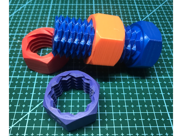
Two Way Hex Cap Screw & Nuts by AdamWP
Remix of a two way screw. Made the head & nuts hexagonal and designed a new two way nut. * Also added a longer screw.The two way nut will tend to find the path of least resistance and may "plinko" back and forth down the screw.
 www.thingiverse.com
purplezr2
Well-known member
Iphone user? Get a Magchanger, no alignment issues.It's time for me to start designing and printing a wireless charger base for the new phone in the new car. I've got a lovely qi charger disc for my bedside. It's very affected by alignment. The jungle place just sent me another to figure out for the car. If it pans out, I'll print a second to keep the phone aligned on the bedside disc.
kaymccampbell
Well-known member
I'm allergic to fruit.Iphone user? Get a Magchanger, no alignment issues.
HPRifleman
Member Emeritus
I've been thinking about a related question of late. How do you decide when to shift from 3D printers to molding parts? For example, I understand Prusa likes the idea of using reprap parts in their printers. However at some point, molding does become cheaper if volumes are high enough. Would Prusa be able to lower their prices if they redesigned the Mk4 to use more molded vs printed parts?
Are any of your volumes high enough to consider molded parts? Is that something you have considered?
I'm kind of curious how the math works out for various people and where the cross over point is. 3D printing is cool because something like an X1C is dirt cheap by the standards of almost any other type of production tooling (molds, machining etc). It's also inherently very flexible with almost no overhead when switching between different parts. But the material cost is much higher than commodity grade resins, the cycle times are likewise MUCH higher than molded parts (perhaps 30 seconds vs hours).
Do you think customers notice or care that the parts are 3D printed instead of molded? - of course don't answer if you think that's something between your operation and your customers. I'm just curious if people who many not be familiar with 3D printing vs the common molded plastic stuff would note the difference.
As the printers become cheaper and faster I do think we will see more low volume parts move from molding to printing. I love that the prices are cheap enough that printing production parts is even an option at reasonable prices.
Using 3D printers in lieu of injection molding is being done now. But the consumer level printers can't deliver the quality of part that more advanced machines can. So the printers that are used in many of these applications either cost in six figures or work on a leased business model. In low volume applications such as aviation and specialized automotive, 3D printers are delivering production parts today.
The right printer can provide flexibility of product mix, choice of materials (rigid, elastomer, or bio-compatible), as well as the freedom to design parts that cannot be injection molded.
my intended value was "does this fit a coke can". more like .1" +- tolerance allowed.0.007" across a few 3D printed parts seems pretty good. Assuming your nominal was your intended value that's +-0.0035"
How much does mold polishing impact dimensions? guy holds the buffer in one spot too long does that vary it?When we think about tolerances we typically view several things as contributing to our numbers. So a +-0.005" dimension doesn't assume that the parts would vary that much. For example, we might assume a process variation of no more than 2/3rds of that +-0.005. We give the other 1/3rd of the range to the size of the mold cavity itself.
Let's assume you have a part with an important length of 1.000+-0.005". The first thing we need to do is get the mold tool made correctly. Ignoring shirnk for the moment, the person making the mold pocket might make it a bit too long or too short. So rather than a perfect process producing a 1.000" long part, it actually produces 1.002" long parts. Now as you run your parts over time the process can shift. The mold temperatures might drift between summer and winter, the batches of resin might have small variations that result in changes in shrinkage or molding pressure etc. Those things cause your nominal 1.002" long part to drive another 0.002". Thus over the time you run this part you see as high as 1.004 and as small as 1.000".
Oddly enough i noticed changes in my open frame printers when it went from summer to winter. caused major warping.
thats like 50x times more complicated than i need in my life for cup holders.Now your production volume goes up and you order a second tool to keep up with demand. When making the second 1" feature the tool maker cuts it a bit short. 0.999. That's still OK since your 0.002" process shift puts you at 0.997-1.001". But perhaps that 1" feature is in part of the tool that will erode over time due to tool wear. Now the nominal shifts up 0.002" That means your long cavity as a new nominal of 1.004" and when process is on the long side the part fails tolerances.
Now consider if you not only have more than one mold for the same part but each mold has 4, 8 or more cavities. Sometimes people find themselves in the unfortunate situation where we can't truly mix and match parts. Say cavity 1 of the part A can't mix with cavity 8 of part B. It becomes a real mess.
As for how to measure that stuff, what you are doing is fine for this discussion. I mean metal calipers would be good... and we want them to have a traceable calibration that's up to date... actually we need you to use a repeatable clamping force. Now that I think about it, perhaps we should just put that part into a video comparator or CMM machine. Well, since the volumes are low perhaps we should use an industrial CT scanner. Those are nice since they can directly compare the scanned data with your CAD model. That's really handy when you need to verify that a whole surface is flat within a certain tolerance or you have a compound curve that needs to be tightly controlled.
sounds like i need to measure my apollo calipers with another set of calipers to see if they are calipering ok.
Then we start getting into how to actually do the tolerancing... yeah, it gets complicated after a while. Fortunately, a lot of the time it's not that hard and a lot of the time our parts don't need to be that precise.
At work we normally use CMM or CT scanners to get our dimensions. CT scanners would only be used during tooling qualification, not for continuous checks. We also have a rule (which is common industry practice) that the tool used to measure the dimension should be accurate to 10x the dimension you care about. Thus if you care about measuring to the 1/10th mm you would need to use tools that measure to the 1/100th mm. I have a similar set of plastic calipers and use them quite a bit. However, with a tool like that they typically say the last bit is often unstable. If you have a true measure that varies between 14.249 and 14.251 (a very small 0.002mm difference) those calipers might show it as a 0.1 variation of 14.2 to 14.3 (assuming they don't truncate vs round). I measured a pair of 3D printed hex nuts that were on my desk. They appear to be nominally between 20.4 and 20.6mm across the flats. I don't know the intended dimension since they were a downloaded file. I'm getting less than 0.1mm variance across the sides assuming I avoid the seam where the printer moved to the next layer (the steel calipers measure to 0.01mm). The parts I was measuring are similar to this model
Two Way Hex Cap Screw & Nuts by AdamWP
Remix of a two way screw. Made the head & nuts hexagonal and designed a new two way nut. * Also added a longer screw.The two way nut will tend to find the path of least resistance and may "plinko" back and forth down the screw.
I wonder what kinda tests we can do across the fleet that GJ has.
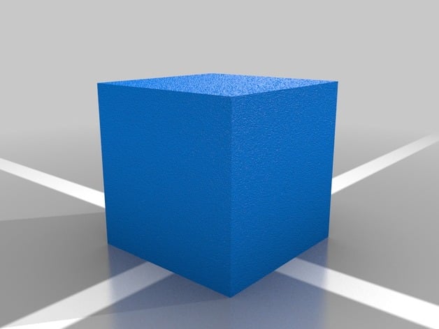
Should we all print a 1" cube with the same layer height/etc and see what our variance is?
Solidworks just debuted a $48/yr program. Anyone giving that a try yet? I find myself frustrated with Fusion's lockdown on my files and the inability to download them. Im wondering if solidworks allows that.
I'm using it. I haven't run into a feature that's missing yet. Includes an online only version of modelling software, but I haven't really tried with that.
I think the biggest limitation is that with the hobby version, you can open files made in the full version, but not vice versa. Models you make on the cheaper maker version cannot be opened by the full versions of the software....if I remember correctly.
niget2002
Well-known member
We'd have to print the same cube with the same material at the same outside temperature/humidity for it to be an accurate printer comparison.Should we all print a 1" cube with the same layer height/etc and see what our variance is?
LeonardY
Well-known member
You forgot with the same alcoholic beverageWe'd have to print the same cube with the same material at the same outside temperature/humidity for it to be an accurate printer comparison.
We'd have to print the same cube with the same material at the same outside temperature/humidity for it to be an accurate printer comparison.
like outside outside or just in the room its in?
unless you're keeping your printer outside. If you're cold, they're cold; bring um inside.
AirMech#406
Well-known member
- Joined
- Sep 29, 2021
- Messages
- 142
The types of issues you are reporting are clear indications of moisture saturated filament. While it is not always necessary to dry PETG. It is not uncommon (in my experience) to have wet filament out of the box or have filament that needs to be dried after being out for a month. (MatterHackers I have found to almost always need drying before printing) If you look in the TDS of many of the different filaments, it will actually give a table displaying how long it will take the filament to become fully saturated in a given humidity. I guess what I'm trying to say is I understand your frustration, but this is an issue that comes with 3D printing.No I have not dried the filament. I don't own a drier and frankly I find it BS that we should need to dry new filament right out of the package. I've been reading about it, but have been resisting it. I'd like to be sure of my settings before resorting to blaming it on moisture. Its been in the AMS for a few days now with the other filaments and my indicators read that it should be dry. I do realize the PETG is much more susceptible to moisture.
niget2002
Well-known member
Mine does live in the shop. It's why I put a heater in the chamber.like outside outside or just in the room its in?
unless you're keeping your printer outside. If you're cold, they're cold; bring um inside.
Welp, I've attempted to print PETG on the p1s. It has not gone smoothly....
There's stringing, theres spaghetti, theres uneven walls and botched layers. TempTower didn't tell me much, I need to change the temps on the layers for petg (up them). Anything 230 and lower was useless anyhow of course.
I have tried some helpful settings from one of our resident experts and they failed.
I tried default and it failed.
I tried several combos, hoping to find a middle ground, and they failed.
I tried "Donnie's" settings from a site and youtube and it failed.
I can get more details to provide, but I'd like to hear more on everyone's P1s/x1 PETG experiences and how they got it to print. Let's say you started at Default Bambu PETG settings, what did you need to tweak for the filament, and the print process? My temps have been from default to 265, speeds slowed way down and sped up, I must be mixing/missing something in the combination that just isn't right.
what brand of PETG.
so me help god if its overture.
XJSuperman
Well-known member
Bambu
LeonardY
Well-known member
My entire garage is in a hot dry box...Mine does live in the shop. It's why I put a heater in the chamber.
MadeByMiller
Well-known member
Welp, I've attempted to print PETG on the p1s. It has not gone smoothly....
There's stringing, theres spaghetti, theres uneven walls and botched layers. TempTower didn't tell me much, I need to change the temps on the layers for petg (up them). Anything 230 and lower was useless anyhow of course.
I have tried some helpful settings from one of our resident experts and they failed.
I tried default and it failed.
I tried several combos, hoping to find a middle ground, and they failed.
I tried "Donnie's" settings from a site and youtube and it failed.
I can get more details to provide, but I'd like to hear more on everyone's P1s/x1 PETG experiences and how they got it to print. Let's say you started at Default Bambu PETG settings, what did you need to tweak for the filament, and the print process? My temps have been from default to 265, speeds slowed way down and sped up, I must be mixing/missing something in the combination that just isn't right.
The types of issues you are reporting are clear indications of moisture saturated filament. While it is not always necessary to dry PETG. It is not uncommon (in my experience) to have wet filament out of the box or have filament that needs to be dried after being out for a month. (MatterHackers I have found to almost always need drying before printing) If you look in the TDS of many of the different filaments, it will actually give a table displaying how long it will take the filament to become fully saturated in a given humidity. I guess what I'm trying to say is I understand your frustration, but this is an issue that comes with 3D printing.
I agree, the next logical step is to dry the filament for at least 24 hours (I dry PETG for 24 hours at 65C). The stock filament profile should work just fine, especially for Bambu's own filament. PETG is not hard to print with, but it can be frustrating compared to PLA. I've printed much more PETG than PLA over the years, and I always dry it before use.
However, let's see what you're trying to print. Were there issues printing the temp towers, aside from being inconclusive?
slodat
ALLIANCE MEMBER
I have never dried any filament. I have printed PETG that was open to the shop environment three years and it went well. I live in the high desert. I’ve printed about 100kg of Overture PETG. I did have the temps slightly higher than the default profile on the Prusa i3. On the XL and X1C’s I use all default settings on PETG and ABS. I’ve always assumed my low humidity was why I get away with no filament drying.
Bambu
and my settings didnt work? interesting. set it back to factory everythig. use bambu PETG profile. same results?
XJSuperman
Well-known member
Yes. The fact that even defaults didn't work is the only reason I am entertaining the path of drying the filament. As bad as this is, it seems like it would have been stored in a lake before it got packaged. The dryer should be here tomorrow or Monday.and my settings didn't work? Interesting. Set it back to factory everything. Use Bambu PETG profile. Same results?
Temp towers couldn't complete. Barely made it past the second level, but remember, I didn't change the temps so it was the same print I did for PLA, so I expected issues at a certain point. These were bad from the beginning. Im trying to print a shelf that will hold spices on a smoker. It covers the width of the plate and has a rather thick bottom, so there are a lot of layers happening before it even really gets to the walls. I am not touching it again until the dryer arrives since thats the common blame: moisture.However, let's see what you're trying to print. Were there issues printing the temp towers, aside from being inconclusive?
MadeByMiller
Well-known member
Post some photos if you have any please. Is the part warping off the build plate during the print?Yes. The fact that even defaults didn't work is the only reason I am entertaining the path of drying the filament. As bad as this is, it seems like it would have been stored in a lake before it got packaged. The dryer should be here tomorrow or Monday.
Temp towers couldn't complete. Barely made it past the second level, but remember, I didn't change the temps so it was the same print I did for PLA, so I expected issues at a certain point. These were bad from the beginning. Im trying to print a shelf that will hold spices on a smoker. It covers the width of the plate and has a rather thick bottom, so there are a lot of layers happening before it even really gets to the walls. I am not touching it again until the dryer arrives since thats the common blame: moisture.