I like making them so the ends are like .010 larger than the threads on the nut. It drives people more crazy thinking it went over the ends.
Haha, that's awesome!


I like making them so the ends are like .010 larger than the threads on the nut. It drives people more crazy thinking it went over the ends.


A dozen or so years ago I thought it would cool to make a very tiny "magic cube" (or whatever they are called). I made this on a Bridgeport milll with a 2-axis ProtoTrak control. I was making tiny parts at that time in my career. I don't think I have the same patience today.

 2019-06-07_09-19-53 by Griffin93, on Flickr
 2019-06-07_09-19-44 by Griffin93, on Flickr
 2019-06-07_09-19-36 by Griffin93, on Flickr
 2019-06-07_09-19-27 by Griffin93, on Flickr
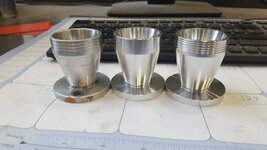
Make a couple of brake rotor hats for a customer's race car last week. These take bolt on style rotors like the circle track folks use.


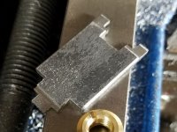
Knocked out a small fixture the other day for machining receivers from raw forgings. The plans came from Ray Branden (Google will get you to the plans), so he deserves the credit for a well done design. The material is 12"x3"x.500" 6061 aluminum. I think I used .500", .250", and .375" end mills. WD40 for lube. The angle finding cube (as seen in one of the pics) was used for setup for the 10° draft angle cut. This was kinda fun; for $3 I had a good time turning knobs. I need to buy more tooling to finish out a receiver, but maybe toward the end of the summer I'll try to get one done.


turned on a chevalier cnc lathe and the holes punched in on a regular knee mill.^Those intake stacks are awesome, what kind of machinery were they made on?^
Didn't you also convert your RF30 to CNC? unless I'm thinking of someone else.


 I made it in two pieces so it can store flat in a drawer...


Nice projects there. They don't have to be exotic, just the ability to make parts yourself is satisfying alone. Heck, I didn't even make any parts and I'm pretty stoked about what I accomplished this afternoon i.e. finally learned the importance of using proper feeds and speeds and surprised myself what my cheap mill/drill can actually do lol. Previously I was making what looked more like metal dust in comparison lol
A well used 1/2" HSS 4FL endmill, 1500 RPM, feed was 13 in/min, 1/2" DOC, .1" WOC, conventional milling...no sweat at all for the cheap mill/drill.
Bumped the WOC to .15" I could feel slight strain but still pretty good finish.
Bumped the WOC to .2" that's when it started squealing. All dry cutting aluminum.
This is side-milling of course, I'll have to figure out the slotting, which is always tough to do in aluminum because chips tend to weld themselves on to the cutter especially with the cutter being the same width as the slot and chip evacuation is an issue.
I use WD40 for lube on aluminum, which is common practice. For slots try going with a smaller diameter end mill and do a center cut and then do a pass on both sides of the slot to finished dimension. 1/2" depth of cut with a 1/2" end mill seems like a big bite on a mill drill, but I could be wrong. My experience with such machines is limited.
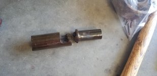
Anyone want to make this part from a Blackhawk S4 jack?


Anyone want to make this part from a Blackhawk S4 jack?
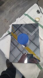
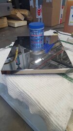
I recently acquired my Bridgeport, so I've been doing a lot of small projects while I build up my inventory of tooling. When I was in school, we had wood table covers that dropped into the T-slot grooves to keep them clean and protect the table. I really liked them, but I prefer working with metal.
I downloaded a 2D CAD drawing of my Kurt vise and imported it into Fusion 360 and quickly drew up the covers. I made the covers .25" longer than the table to account for variances in vice centering. I made them 8.75" wide instead of 9" (width of the table) to also account for vise placement without having an overhang on the edges.
Big Blue about the only thing I would do different it to have made them about 6" different in length to each other. It is a good practice to offset your vice each time you mount it up, this will allow the machine to wear more evenly instead of all I the middle. 3" offset will widen your everyday area out about ~6+" and this will make a huge difference in using your machine. If you have ever used one where the center is so loose it can't do anything without jumping all over the place and you can't even get to the ends as the "Gibbs" tighten onto the unworn ends, you will understand what we are trying to avoid. You already have some adjustment in your "table keys", now you may think about turning up the last three inches on the opposite end to allow this, and adds a shield to protect your hands during heavy fly cutting on the X axis, [this effectively shortens both of them 3"] so you can switch them from end to end [and rotate with your centered keys]. They turned out beautiful and very functional and you can still offset with the 3" "flanged" ends. I plan to do some of these if I ever get mine powered up. [Closer this week, I just yesterday picked up my newly rewound/re-bearinged motor now I just need proper power in the garage and a VFD!I recently acquired my Bridgeport, so I've been doing a lot of small projects while I build up my inventory of tooling. When I was in school, we had wood table covers that dropped into the T-slot grooves to keep them clean and protect the table. I really liked them, but I prefer working with metal.
I just can't wait!  ] Harry
Big Blue about the only thing I would do different it to have made them about 6" different in length to each other. It is a good practice to offset your vice each time you mount it up, this will allow the machine to wear more evenly instead of all I the middle. 3" offset will widen your everyday area out about ~6+" and this will make a huge difference in using your machine. If you have ever used one where the center is so loose it can't do anything without jumping all over the place and you can't even get to the ends as the "Gibbs" tighten onto the unworn ends, you will understand what we are trying to avoid. You already have some adjustment in your "table keys", now you may think about turning up the last three inches on the opposite end to allow this, and adds a shield to protect your hands during heavy fly cutting on the X axis, [this effectively shortens both of them 3"] so you can switch them from end to end [and rotate with your centered keys]. They turned out beautiful and very functional and you can still offset with the 3" "flanged" ends. I plan to do some of these if I ever get mine powered up. [Closer this week, I just yesterday picked up my newly rewound/re-bearinged motor now I just need proper power in the garage and a VFD!