To avoid these ads, REGISTER NOW!

This could be the ultimate welding table.

AMCguy

Well-known member
Joined
Dec 23, 2009
Messages
2,022
Location
Sunshine Coast, BC Canada
This could be the ultimate welding table, or it could end up being very average.

Either way it will be the culmination of many days of viewing the welding table threads here on the Garage Journal, surfing the web, lying in bed at night thinking and struggling in my garage without a proper one. I have seen some cool ideas here and come up with a few good ones of my own, so if this is a success some of you can take partial credit for it.
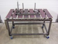
First Picture;
Here is my main inspiration. It's a crappy class room or office table I got from a neighbor's garage sale about ten years ago. It's 30''x60'' and it's 30'' tall. The top is warped, the legs are wiggly and its rusty, but the size is ideal for what I want to do. I have used it a lot and also cursed it a lot.

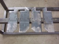
I wanted a top I could could clamp to anywhere on its surface. So this one will have a grid of eight 6''x1/2'' flat bar planks 30'' long. They will be spaced 1 1/2'' apart. Much like the Strong Hand fab table that costs more than I make in a year.

Second Picture;
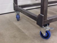
So here we go. I cut all my metal. Got some good casters that lock solid both ways.

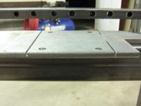
I started by drilling all the holes to mount the top. Each plank will sit on a set of four 1/2''x2 1/2'' fine thread jacking bolts. There will be one near the corner of each plank. This way I can adjust them individually, have them all dead even or I can remove one or more if I need to. There will be a 1/2'' hole in the top flange of the 3''x2'' top rail for each bolt and a pair of nuts will sandwich the flange to hold the bolt into place. A corresponding 1 1/8'' hole in the bottom so I can get a socket on the bottom nut.

Third Picture;
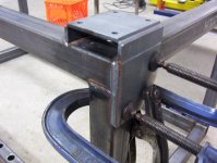
Here is the hole sawing operation. I consumed a cheap Canadian Tire hole saw. I hope I can use it for an Exchange a Blade hole saw.

I actually screwed up here. I forgot that the end hole wasn't needed. I can get to the bottom nut from the opening in the end of the tube and the upright attaches where the hole shouldn't be. I had to weld the holes shut because I didn't want debris to find its way in.

Fourth Picture;
Here is the side ready to weld. It could be the front or the back as the two are identical. It's hard to get set up for welding together a welding table when you don't have a proper welding table to do it on.

The welding will have to wait until tomorrow. It was getting late at this point. More to follow.
 

Attachments

  • 100_1600.jpg
    100_1600.jpg
    78.7 KB · Views: 1,136
  • 100_2056_zps7720f79e.jpg
    100_2056_zps7720f79e.jpg
    87.8 KB · Views: 1,007
  • 100_2057_zpsed3c27fe.jpg
    100_2057_zpsed3c27fe.jpg
    100.9 KB · Views: 986
  • 100_2058_zps2ac4352a.jpg
    100_2058_zps2ac4352a.jpg
    102.4 KB · Views: 1,052
Last edited:
To avoid these ads, REGISTER NOW!

fatboy99

Well-known member
Joined
Apr 23, 2009
Messages
908
Location
Indiana
I love these welding table build threads. I'm collecting all kinds of idea's for when I build mine. Looking forward to your progress.
 

Chuck McB

Well-known member
Joined
Mar 21, 2012
Messages
745
Location
Alabama
This is going to a very enjoyable thread so I'm subscribed too. The casters locking both ways is the only way to go!
 

Mr.N

Well-known member
Joined
Jul 13, 2005
Messages
2,221
Location
Mpls, MN
The ultimate welding table

This could be the ultimate welding table, or it could end up being very average.

Either way it will be the culmination of many days of viewing the welding table threads here on the Garage Journal, surfing the web
Looks great so far! Why not include a couple links to those table you liked?

Are you going to drill a bunch of holes into your plate like the Strong Hand tables?

Just don't keep my waiting on an update. :thumbup:


.
 
Last edited:

shieldcracker

Member
Joined
Jul 5, 2011
Messages
24
It is a chemical treatment applied as solution to stainles steel, to prevent (passivated) corrosion caused by impurities on the parent metal.
 

Jose G

Well-known member
Joined
Aug 1, 2012
Messages
46
Location
Canada, Quebec
really great start, hope to see update soon!

@shieldcracker: it looks like normal steel, i guess he will paint it or leave it rust slowly for the 50 years to come
 
OP
A

AMCguy

Well-known member
Joined
Dec 23, 2009
Messages
2,022
Location
Sunshine Coast, BC Canada
Also Subscribed!

Looks to be a great table, what kind of stuff do you plan on fabricating on it in the future?
First thing I'll be building is my engine run-in stand. Then I'll be building an auto rotisserie. I started a small business fabricating brackets, crossmembers, performance suspension and other small parts for AMCs a while back but had to put it on hold because I was too busy with my main livelihood. I hope to get that back up and running soon. This table and the various fixtures I'll be building will play an important part.
 
To avoid these ads, REGISTER NOW!
OP
A

AMCguy

Well-known member
Joined
Dec 23, 2009
Messages
2,022
Location
Sunshine Coast, BC Canada
Ok now for the update. I got the basic frame built. It was no easy task. With absolutely nothing to clamp to, the pieces were free to move around as soon as you start welding. Distortion control on something like this takes a lot of thinking. It's a lot harder to fix something that has gotten out of square than it is to prevent it from doing so.

First Picture.
You have heard people say "weld one corner then weld the opposite one". Well in a case like this, if you do that you will only compound the distortion. You have to weld one corner, then weld the adjacent one. Even then you have to pre-distort the work so the weld pulls it back into square. I spent all day setting up and welding this.

Second Picture.
You wouldn't think of it but this shape has twenty four inside corner welds and sixteen outside corner welds. In the early going its very easy to get it out of shape. As it gets more complete it begins to hold it's self square. I can tell you this thing is dead nuts square anywhere you care to check it.

Third Picture.
Here is the requisite weld close up. I'm sorry. I see now that I didn't hold the camera very still.

Fourth Picture.
I worked out there (in the garage) from just after lunch until I had to come in and make supper. I did get a chance to sneak in one of my favourite refreshments though. These things are incredible.

Tomorrow I hope to build my custom caster mounting plates and get them welded on. I'll also want to get make a fixture for getting all the jacking bolts in position for welding.
 

Attachments

  • 100_2063_zps1d200ca8.jpg
    100_2063_zps1d200ca8.jpg
    80.2 KB · Views: 972
  • 100_2061_zps25356d7e.jpg
    100_2061_zps25356d7e.jpg
    94.8 KB · Views: 1,059
  • 100_2060_zps031f06f0.jpg
    100_2060_zps031f06f0.jpg
    73.8 KB · Views: 927
  • 100_2062_zpsfa0abb67.jpg
    100_2062_zpsfa0abb67.jpg
    64.6 KB · Views: 1,000
Last edited:

mik641

Well-known member
Joined
Mar 18, 2009
Messages
89
Location
New Zealand
Could have built it on the floor, lay all your pieces and tack the insides of each rhs, then square up by measuring diagonals. then tack on the outside of the rhs facing up and anywhere else you think. get some braces and tack them on for each corner. Youre mig welding it so you shouldnt get too much distortion and even then a tap on the concrete depending on which corner it may be. Its a welding table and if youre going to put a decent slab on top which you really need, a bit of distortion, even 3mm isnt a biggy if you know how to fix it.
 
OP
A

AMCguy

Well-known member
Joined
Dec 23, 2009
Messages
2,022
Location
Sunshine Coast, BC Canada
Could have built it on the floor, lay all your pieces and tack the insides of each rhs, then square up by measuring diagonals. then tack on the outside of the rhs facing up and anywhere else you think. get some braces and tack them on for each corner. Youre mig welding it so you shouldnt get too much distortion and even then a tap on the concrete depending on which corner it may be. Its a welding table and if youre going to put a decent slab on top which you really need, a bit of distortion, even 3mm isnt a biggy if you know how to fix it.
I actually did build a good portion of it on the floor and hated every second of it. I have welded so many things on the floor over the years it isn't even funny. I saved a lot of wear and tear on my back and knees today by doing as much as I did up on the old crappy table.
 

Steevo

Well-known member
Joined
Aug 18, 2009
Messages
8,738
Location
43.49600, -112.04300
This looks like it will be a very nice and very sturdy welding table.
I am anxious to see the top system you are building, because I didn't quite understand your description of how it would work.
 

Mr.N

Well-known member
Joined
Jul 13, 2005
Messages
2,221
Location
Mpls, MN
This looks like it will be a very nice and very sturdy welding table.
I am anxious to see the top system you are building, because I didn't quite understand your description of how it would work.
I think this is the style AMC is shooting for
3488904_lg.jpg
 

R.Anderson

Well-known member
Joined
May 26, 2012
Messages
906
Location
Wisconsin
Looks good, looks like you have your work cut out for ya drilling all those holes in those 1/2" plates.

I'm also working on a fabrication table kinda based off of the strong hold fab tables. here is some pics of the top I had cut out on a cnc plasma cutter. the plate is only 3/16" thick but with 2" x 1/4" flat bar and 25-2" long 5/8"ID 7/8"OD pipe grid work under it it will be plenty strong for what I plan on using it for.
 

R.Anderson

Well-known member
Joined
May 26, 2012
Messages
906
Location
Wisconsin
Here is some pictures of the top i'm going to use.
 

Attachments

  • 1228120912.jpg
    1228120912.jpg
    135.7 KB · Views: 1,509
  • 1228120912b.jpg
    1228120912b.jpg
    140.4 KB · Views: 1,298
  • 1228120912a.jpg
    1228120912a.jpg
    135.3 KB · Views: 1,350
  • 1228120911.jpg
    1228120911.jpg
    140.3 KB · Views: 2,108
OP
A

AMCguy

Well-known member
Joined
Dec 23, 2009
Messages
2,022
Location
Sunshine Coast, BC Canada
He is 6'2" and the table is 30". (know his height from his drill press thread)
I like a low table, since projects can make them seem quite tall.
Yup I'm 6'2''. I actually decided on having the top at 36''. That way I will have to bend over a little less and I will be able to pull a stool up to it when I'm doing time consuming work like layup and tig welding.
 
OP
A

AMCguy

Well-known member
Joined
Dec 23, 2009
Messages
2,022
Location
Sunshine Coast, BC Canada
Looks good, looks like you have your work cut out for ya drilling all those holes in those 1/2" plates.

I'm also working on a fabrication table kinda based off of the strong hold fab tables. here is some pics of the top I had cut out on a cnc plasma cutter. the plate is only 3/16" thick but with 2" x 1/4" flat bar and 25-2" long 5/8"ID 7/8"OD pipe grid work under it it will be plenty strong for what I plan on using it for.
I won't be drilling all the holes like the StrongHand table has. With 1 1/2'' between the planks, I can clamp anywhere I want to on the table's surface.

Your table top looks good so far. If you don't ming me saying so, I hope you don't plan to stitch weld the top to your supporting grid. It will pull and make the top wavy. I would recommend rosette welding instead. Either from the top down or the bottom up, there will be no distortion.
 
OP
A

AMCguy

Well-known member
Joined
Dec 23, 2009
Messages
2,022
Location
Sunshine Coast, BC Canada
so why did you drill all those holes for again
The holes are for the top. There will be eight planks that will each sit on four adjustable pedestals. The pedestals are just a bolt with the head welded to the underside of the plank. The two nuts are for adjusting up and down. The holes in the top of the tube are for the bolt to sit in and the large holes in the bottom are for a socket to get on the bottom nut. I'll be posting a picture of the assembled but unpainted table tomorrow.
 
OP
A

AMCguy

Well-known member
Joined
Dec 23, 2009
Messages
2,022
Location
Sunshine Coast, BC Canada
Sorry I have nothing to post today. I had a few things to do in the house this morning.

As soon as I got out to the garage this afternoon my pager went off. I'm a volunteer fire fighter. That call took all afternoon. Got home just in time for supper and headed out to the garage and my pager went off again. I just got home. I'm going to have a hot bath and sleep like a baby.

We'll see how tomorrow goes.
 
OP
A

AMCguy

Well-known member
Joined
Dec 23, 2009
Messages
2,022
Location
Sunshine Coast, BC Canada
I made a little more progress today.

First Picture.
Mounting casters that attach with a plate always poses a challenge for me. I don't like the look of a flat plate welded to the bottom of a leg or the underside of a tube. I wanted to do something a little more interesting to look at. This of course means harder to build if you don't have a lot of fancy equipment. Below you can see the mounting plates I cut out of 1/4''x4'' flat bar.

Second Picture.
I wanted a couple of 90% bends in them, but Heating them up with a torch takes a lot of gas and if the heat soaks too far from the line you want to bend on, the radius gets big and hard to control. So I scored them with a zip wheel so I could give them a tight radius bend with very little heat. Then all I have to do is an outside corner weld to make it look finished. Here is a close up.

Third Picture.
This is the plate bent and partially welded into place.

Fourth Picture.
Below is the outside corner weld. This I screwed up. By scoring the plate as deep as I did, It opened up kind of wide when I bent it. This left a pretty big gap to fill back in. I got lazy and tried to do it in one pass. This is actually beyond the limit for a single pass. I should have done three. In hindsight, I shouldn't have scored the plate as deeply. That way I would have had a smaller gap to fill and I could have done it with a single pass. I'll touch this up later. They're going to be sanded to a nice outside radius to make them look like they were bent in a press brake.

Fifth Picture.
This shows how the casters mounted. I like how this design element turned out.

Sixth Picture.
And here is the complete deal. You can see how the individual bolts allow me to adjust each plank up or down. I can make them dead even. I can even remove one or more of them to accommodate an irregular workpiece. You can see how this design provides unrestricted clamping anywhere on the table top. I can drop a clamp in anywhere from the top, or slide one in from the side. I can clamp all around the edge except where the bolts are. Also note that if you position the joint to be welded over the gap, you can do a full vertical weld without hitting the table top. Notice I found a neat little place to keep my framing square handy.

I'm going to leave it unpainted for now. I still want to come up with some kind of bottom shelf and a set of bunks for keeping shorter lengths of material on. I also want to make a detachable mount at the end of the table for my drycut saw. It will mount with it's surface the same height as the welding table. That way the welding table will double as an infeed table.

I want to keep it as simple and clean looking as possible. I don't want all my grinders and clamps hanging from it. I have a place to store them out of sight. I do like welding stuff though, so who know what it's going to look like this time next year.

I'll keep everybody posted.
 

Attachments

  • 100_2064_zps1d76cd31.jpg
    100_2064_zps1d76cd31.jpg
    85.6 KB · Views: 977
  • 100_2066_zps55c84af8.jpg
    100_2066_zps55c84af8.jpg
    58.8 KB · Views: 921
  • 100_2069_zpsda67a62a.jpg
    100_2069_zpsda67a62a.jpg
    84.7 KB · Views: 912
  • 100_2070_zps82777b6e.jpg
    100_2070_zps82777b6e.jpg
    59.7 KB · Views: 873
  • 100_2072_zpse29a447b.jpg
    100_2072_zpse29a447b.jpg
    73.9 KB · Views: 942
  • 100_2071_zpsc10152bb.jpg
    100_2071_zpsc10152bb.jpg
    78.4 KB · Views: 1,234
Last edited:

king nero

Well-known member
Joined
Dec 27, 2010
Messages
1,469
Location
Belgium
Isn't it a whole lot of work adjusting each individual tabletop plate?
I like the idea, but I'd've thought that's a bit too much possibilities of adjusting...
I also would say, by using such a system, you can't really tack weld something to the table because the plates would distort easily. Or maybe you don't intend to?
 
OP
A

AMCguy

Well-known member
Joined
Dec 23, 2009
Messages
2,022
Location
Sunshine Coast, BC Canada
Isn't it a whole lot of work adjusting each individual tabletop plate?
I like the idea, but I'd've thought that's a bit too much possibilities of adjusting...
I also would say, by using such a system, you can't really tack weld something to the table because the plates would distort easily. Or maybe you don't intend to?
It only takes a couple of minutes to get them all even. From then on, It would only be required if I had removed and replaced one. The main idea behind building it this way was, I could ensure it was dead flat after it was all assembled. I was concerned that if I had somehow welded the planks to the table frame, they could end up distorted or less than dead level. That would have been a "whole lot of work" for me to overcome.

I can't think of a reason I would ever need to tack to it.
 

R.Anderson

Well-known member
Joined
May 26, 2012
Messages
906
Location
Wisconsin
I won't be drilling all the holes like the StrongHand table has. With 1 1/2'' between the planks, I can clamp anywhere I want to on the table's surface.

Your table top looks good so far. If you don't ming me saying so, I hope you don't plan to stitch weld the top to your supporting grid. It will pull and make the top wavy. I would recommend rosette welding instead. Either from the top down or the bottom up, there will be no distortion.

I like your caster mounts, the table looks very versatile.

The top will be welded via the 25 holes leaving a 5/8" hole and intermittent welds along the four edges. Prior to welding the edges ill temporary reinforce the edge with a h-beam and c-clamps. This should minimize the distortion.
 
To avoid these ads, REGISTER NOW!
Top Bottom