You are using an out of date browser. It may not display this or other websites correctly.
You should upgrade or use an alternative browser.
You should upgrade or use an alternative browser.
This could be the ultimate welding table.
- Thread starter AMCguy
- Start date
Farmall450
Well-known member
Sorry to bring this back from the dead...but awesome build!
raddksn
Well-known member
 I would like to see some projects you build on this great table. You GOT SKILLS MAN !!!!!
bsaint
Well-known member
Now to box it in and make it down draft...thats the ultimate welding table.
There was some discussion of deflection. If that ever became a regular problem, you could but another long support down the center of the long dimension of the table and just use 1 bolt in the center of each plate. This wouldn't hinder clamping.
Again, very, very nice design and build. Caster plates are great.
Again, very, very nice design and build. Caster plates are great.
wellpoison
Well-known member
you have lots of skill. i would love to see more projects! i love the way you did those caster mounts.
absintheisfun
Well-known member
- Joined
- Feb 7, 2010
- Messages
- 84
Just tagging this one for later reference when I shoplift your ideas ")
Awesome table man!
Awesome table man!
Nice table. I liked it so much that I am in the process of making one very much like it. Mine is going to be 3' x 8'. A local supplier had some 5/8" x 6 flat bar that they had extra that I got very good price. My rails (which are 2" x 4" x 3/16") will be 30" apart so that I'll have 3" over hang on each side. Also, I decided rather than weld bolts to the bottom of the slabs, that I would instead drill and tap holes and use 1/2" x 3" studs. This way I figured that if I needed to, could always flip a slab over if the top side got messed up.
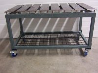
I already drilled and tapped the top pieces and am in the process of drilling the holes in the rails. I wanted to ask you if you were to do it again, is there anything you would do differently? I have some expanded metal and i have thought about making a shelf at the bottom of my rails so anything I drop through the gaps in between won't have to hit the floor, but only drop 6" or so. I am worried that in addition to the stray tool that I might end up with a one more spot for debris to build up.
I already drilled and tapped the top pieces and am in the process of drilling the holes in the rails. I wanted to ask you if you were to do it again, is there anything you would do differently? I have some expanded metal and i have thought about making a shelf at the bottom of my rails so anything I drop through the gaps in between won't have to hit the floor, but only drop 6" or so. I am worried that in addition to the stray tool that I might end up with a one more spot for debris to build up.
I'd like to thank everybody for all their comments.
frsava, It sounds like you're going to have a great table. In answer to your question, I would have used 2''x4'' for the top rail if I had it in my shop at the time. I know the 2''x3'' is adequate but I think it would have looked better with 2''x4''.
frsava, It sounds like you're going to have a great table. In answer to your question, I would have used 2''x4'' for the top rail if I had it in my shop at the time. I know the 2''x3'' is adequate but I think it would have looked better with 2''x4''.
Adam McLaughlin
Well-known member
That did come out well
Bravo
Bravo
if you folks build, in effect slotted tables, make the slots a tad over 5/8"......
then you won't need C-clamps, you can use T-slot clamps like every milling machine in the World and they cost peanuts compared to C-clamps
my welding table top is 21"x 64" (perfect for building motorcycles) its Navy plate, 1/8" of stainless bonded to 5/8" of steel, its rimmed with 3/8x3x3
deflection? i don't think so
Last edited:
CARS
Well-known member
3/4". Oh my.
Richard D
Well-known member
if you folks build, in effect slotted tables, make the slots a tad over 5/8"......
then you won't need C-clamps, you can use T-slot clamps like every milling machine in the World and they cost peanuts compared to C-clamps
my welding table top is 21"x 64" (perfect for building motorcycles) its Navy plate, 1/8" of stainless bonded to 5/8" of steel, its rimmed with 3/8x3x3
deflection? i don't think so
I like this idea, I already have T nuts for my mill.
What is Navy Plate? Where can I get it? How about pictures of your table?
e30bradley
Well-known member
this is one of the nicest welding tables I've seen built here.. and there has been allot built.
I like this idea, I already have T nuts for my mill.
What is Navy Plate? Where can I get it? How about pictures of your table?
Ditto.
bldgengineer
Active member
I'm subscribing so I can steal this design later on. By the way, how would you suggest incorporating a vise, tube notcher, and possibly a shrinker/stretcher into your design?
If you're still reading this of course lol
If you're still reading this of course lol
Richard D
Well-known member
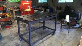
Thanks for the inspiration, I finally built mine:
http://www.garagejournal.com/forum/showthread.php?t=225206
http://www.garagejournal.com/forum/showthread.php?t=225206

i might have missed it but are the legs .120 wall? nice table.
All the tubing used was .125'' I mentioned earlier, that if I was doing it again, I would use 4''x2'' on the upper portion of the table. The 3''x2'' is certainly adequate but I would prefer it look beefier.
I'm subscribing so I can steal this design later on. By the way, how would you suggest incorporating a vise, tube notcher, and possibly a shrinker/stretcher into your design?
If you're still reading this of course lol
For lighter things, I would probably build a mount for each tool that I could clamp to the surface plates rather than have a receiver tube incorporated into the table frame. I wanted my table to be as clean as it could be. I prefer not to have anything else on it. Even though the four casters I used lock, I think the table would move around a bit if I was using a vise attached anywhere.
Thanks for the inspiration, I finally built mine:
http://www.garagejournal.com/forum/showthread.php?t=225206
Your table looks great. If I inspired you (or anyone else) then all the time I took to post this thread was worth it. I'm not very handy with a computer.
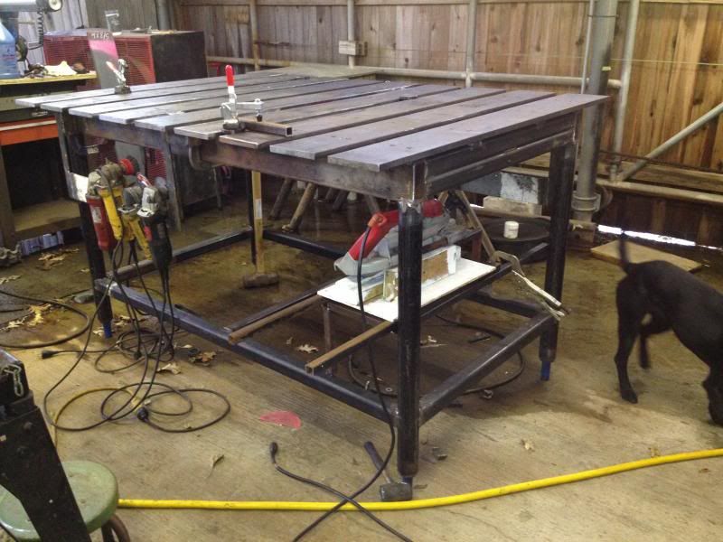
I'd like to thank you all once again for the kind replies and great questions. Here is what the table looks like these days. The only thing I have done is paint it. I've used it quite a lot since it's completion.
Attachments
Last edited:
Doug19
Well-known member
if you folks build, in effect slotted tables, make the slots a tad over 5/8"......
then you won't need C-clamps, you can use T-slot clamps like every milling machine in the World and they cost peanuts compared to C-clamps
my welding table top is 21"x 64" (perfect for building motorcycles) its Navy plate, 1/8" of stainless bonded to 5/8" of steel, its rimmed with 3/8x3x3
deflection? i don't think so
I really like this idea of using T-slot clamps. Anybody ever seen it done or can come up with a reason it wouldn't work?
Richard D
Well-known member
Would work good. I find I like the wide slots in mine since I find c clamps are more convinient.
CUMMINS&CORONET9768
Member
Thanks again for all the kind replies. Here is what the table looks like these days. The only thing I have done is paint it. I've used it quite a lot since it's completion.
Very nice table design. I love this forum
Nice table desing, i used some of guides about welding tables on web and finaly i built my own table.
tw0st3p
Member
Buil-dwelder
New member
- Joined
- Apr 14, 2015
- Messages
- 1
AMCGuy,
Wow. Very nice design, and build. Just found your thread by doing a search on web for a different kind of table, but clicked on the link for your build. Glad I did! I registered here to let you know that your sharing with everyone is excellent! This design is in my fabricating future, in about 3 months from now.
I was originally looking for a spinning rotary table, like a potter's wheel, to aid in cutting circles in/from metal. Would you happen to have killer plans for one of those?, lol!
Greg
TJM2
Well-known member
That table is awesome. Outstanding work, truly. I opened this thread thinking "I can probably pull this off" and got to the end thinking "nope!"
Maybe in the future I will have a little more experience and confidence to attempt a build like this. In the mean time I'm just going to admire the pics. Thanks for sharing!
Maybe in the future I will have a little more experience and confidence to attempt a build like this. In the mean time I'm just going to admire the pics. Thanks for sharing!
bulletpruf
Well-known member
First thing I'll be building is my engine run-in stand. Then I'll be building an auto rotisserie. I started a small business fabricating brackets, crossmembers, performance suspension and other small parts for AMCs a while back but had to put it on hold because I was too busy with my main livelihood. I hope to get that back up and running soon. This table and the various fixtures I'll be building will play an important part.
Interesting! I'm building a 71 Javelin road race project. Difficult to find suspension parts; had a heck of a time finding coil overs. Getting some custom upper control arms made up now. Are you a member at www.theamcforum.com?
Let me know what you'll be producing when you get up and running.
Scott
Adam McLaughlin
Well-known member
I too liked this design well enough to take the idea, modify it slightly and duplicate the application
Very well done !!!
I'd like to see more builds like this
Adam
Sent from my iPhone using Tapatalk
Very well done !!!
I'd like to see more builds like this
Adam
Sent from my iPhone using Tapatalk
richeyc2000
Well-known member
I agree entirely.
I loved this design so much I started from this design.
It's still a work in progress as everyday I see great ideas here like AMCguys and others it keeps evolving. [emoji106][emoji106][emoji3]
Well done and can't wait to see more.
Sent from my iPhone using Tapatalk
I loved this design so much I started from this design.
It's still a work in progress as everyday I see great ideas here like AMCguys and others it keeps evolving. [emoji106][emoji106][emoji3]
Well done and can't wait to see more.
Sent from my iPhone using Tapatalk
Griff93
Well-known member
Thanks for posting this build. I'm going to build another welding table at some point. My current one is to small for a lot of the projects I get into these days at 2'x4'.
CRCRFT78
Member
Nice table design.
hi, great table, love it, very functional. I know this is an old thread but i know it'll be looked at often ppl looking at weld table builds.
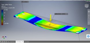
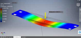
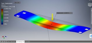
I saw a couple questions about bending moments and how much the bar would support. I have some professional design software that can do basic FEA analysis pretty easy so i thought i'd run a couple simulations to see what your bar would hold. I included pic the explanations are below. The bend you see in these pics is greatly exaggerated to show the shape and direction of the deflection.
TOP BAR 600lb-1 = Load of 600lbs in an area 1.5" wide the width of the bar (see drawing for where i placed the force). Least Safety factor is 3 meaning the bar could theoretically hold 1800 lb before it reached it's elastic limit and the bend would be permanent. A safety factor of 3x is what the guys i work with usually work with but you could easily do 2x which is 1000 lb but would get roughly 1/6" of bend in the middle.
TOP BAR 600lb-2 = shows how much the bar would deflect at 600 lb, i think it was about 1/32"
The twp TOP BAR 1500 lb pics show the same thing as above but with a 1500 lb load.
Also the drawing (the last file) shows the 3/4" diameter "fixed" places to run the simulation and where in i placed the load. I placed the bolts roughly where i figured your bolts to be.
The total for the 8 bars on your table would be an easy 4800 lb across all of them, and that would be all of that weight sitting on a strip 1.5" wide. And that would be a safety factor of 3x. A very stout table you have
Mike