To avoid these ads, REGISTER NOW!

Timber frame to dimensional lumber gable roof

Wiebster

Well-known member
Joined
Jul 18, 2015
Messages
194
Location
Rapid City, Sd
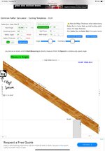
Hi guys, I’ve appreciated all the comments and suggestions on my obstacles to building my own 72’x40’ shop. I’m ready to get this thing shingled but still have a timber frame gable roof to build on the front of it. I have gotten started with the uprights and horizontal beams but I’m struggling with some of the details to tie this into the main roof. Any of the structure that is exposed from underneath, wanted rough cut timbers. Im using stained 2x8 tongue and groove boards for the sheathing on the exposed part so that roofing nails don’t show through. However where the gable crosses over the exterior wall of the shop, I want to switch to dimensional 2x8 lumber to keep the expense and weight down. My ridge beam will be an 8x8 approximately 8’ long. The entire ridge length is about 16’ long. My rafters (4x8’s) will be notched at the top and bottom and will form a peak as they come together at the top. How can I best switch to dimensional lumber once I am above the main roof and out of site from below. My thought was a plywood gusset on the back of the last set of rafters to tie everything together, and then just use a joist hanger on that to continue the dimensional ridge beam the rest of the way. To complicate things, as I usually do, the remaining sheathing will be 5/8” osb, so a 7/8” height difference between the two. Hopefully the pictures will help does what I’m trying to do. The uprights holding the timberframe ridge beam are 8x8s. I had to hollow one out so it would slip over the truss as it stands on the top plate straddling the truss. Open to any ideas. My main concerns are keeping the ridge line straight with two different sheathing heights (and the same 8/12 pitch) and then the 2x8 ridge attachment point on the back of the last rafter. Thanks guys!
 

Attachments

  • IMG_0808.jpeg
    IMG_0808.jpeg
    683.4 KB · Views: 47
  • IMG_0807.png
    IMG_0807.png
    2.6 MB · Views: 50
  • IMG_0811.png
    IMG_0811.png
    5.9 MB · Views: 51
  • IMG_0812.png
    IMG_0812.png
    6.3 MB · Views: 50
To avoid these ads, REGISTER NOW!

BobsF85

Member
Joined
Dec 31, 2013
Messages
11
A few questions... The drawing you show is different structurally from the pictures of the work that you have done so far. The biggest difference being that the timberframe structure shown is a self supporting and freestanding timberframe structure, while what you show in the construction pictures is a two legged structure attached, and structurally dependent on the main building. Additionally, the architectural rendering in img_0808.jpeg exhibits a king post truss design, a design which typically uses purlins rather than a ridgebeam and rafters to distribute structural loads. Is there an architect or engineer involved in this design and does your LHJ require an engineers stamp on this or are you acting as your own engineer on this project. Additionally, I don't see any joinery details or how you are actually keeping these timbers in place. It looks like you might be using screws? Is there actually any joinery or will you be attaching structural metal plate to hole everything together?
 
OP
W

Wiebster

Well-known member
Joined
Jul 18, 2015
Messages
194
Location
Rapid City, Sd
The image 0807 is the closest artist rendition that I could find. Mine will be a two post as shown in the 0811 pic and will be dependent on the main building for support. There will be three sets of rafters and then jack rafters after that over the main roof. There is no engineer and all I have is the drawings from the architect with no stamp required. I will be using 1/4” steel plates to sandwich the connections of the 8x8s. The rafters will be notched to fit over the beams as shown in 0807 and then instead of purlins the decking will be solid T&G 2x8’s over the rafters spaced 2 ft on center. The rafters will be screwed to the 8x8s with Timberlok screws. I hope that explains my plan. IMG_0824.jpeg
 

firebirdparts

Well-known member
Joined
Jun 8, 2016
Messages
10,666
Location
Kingsport, TN
I would run a ridge pole from your 8 x 8 to the building (probably on top of the 8 by 8 adjusted as necessary) and everything else should just fall into place. 2 by 8 is probably enough but I might do a 2 by 10 just for good measure.

To land the other end on the trusses I have to think there's an ocean of information about that on the web. People have to do it all the time.
 
To avoid these ads, REGISTER NOW!
OP
W

Wiebster

Well-known member
Joined
Jul 18, 2015
Messages
194
Location
Rapid City, Sd
So just leave room on the vertical 8x8 king post in order to rest the 2x10 on, using a joist hanger to keep it vertical? Makes sense! You’re right, there are YouTube videos showing how to do jack rafters. My issue is raising them 7/8” higher than the timber frame so the 1 1/2” t&g matches the 5/8”osb. Hopefully it will all make sense once I get the timber frame section built.
 

firebirdparts

Well-known member
Joined
Jun 8, 2016
Messages
10,666
Location
Kingsport, TN
I was thinking the 8x8 ridge runs wild a little bit beyond your wall that hides everything, and you sit on top of that. If you were connecting end to end, that would be a great connection with a hanger, but that would be too low. When you get the ridge pole up even with the top of the rafters you can connect those to each other in a good solid way. If you let the king pole run wild in the upward direction, that would certainly give you something to connect to that is tall enough. Just to be clear I hadn't thought of that.
 

BobsF85

Member
Joined
Dec 31, 2013
Messages
11
Ok, so there are some structural analysis issues. What you are planning is technically considered post and beam construction, not timberframing. Timberframing uses wood joinery and dowels or "trunnels" to hold everything in place.
Post and beam uses steel plates and through bolts.

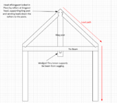
In a true kingpost truss design, the post is actually suspended and held in place by the compression of the rafters. It supports the horizontal tie beam which is in tension between the two posts and prevents outward thrust. You have essentially designed it backwards with the tie beam supporting the king post and the king post supporting the ridgebeam and rafters. This is a structurally flawed design as the load of the entire roof is concentrated midspan on the tie beam, and there is nothing but timberlock screws to contain the thrust at the eaves. Kingpost truss designs are very misunderstood by the general public. Additionally, your hybrid design has nothing to structurally tie the two structures together in any meanigful way. Situating a post over a doorway is also a structural no no unless you have done a proper structural analysis and beefed up the header to handle the loads.
Adding the steel sandwich plates is actually going to weaken your timbers significantly at critical stress points.
Timberframe decorative elements are all the rage right now, but if they aren;t done properly, those big heavy timbers can come crashing down on someones head and make for a really bad day. I am attaching a diagram of a proper kingpost truss design. Perhaps it will help.
 

Attachments

  • Screenshot 2025-05-19 154745.png
    Screenshot 2025-05-19 154745.png
    42 KB · Views: 23
To avoid these ads, REGISTER NOW!
Top Bottom