To avoid these ads, REGISTER NOW!

Below 265 SQ/FT Tiny Tokyo Shop

All workspaces below 265 squarefeet.
OP
B

Bakafish

Well-known member
Joined
Feb 7, 2017
Messages
477
Location
Tokyo
I need to confess something. I recently got turned on to a really nice online used industrial parts shop (Japan Only) and I've been going a bit mad on it...

At first it was just a few items I knew I wanted, a little rotary encoder for the mini-lathe project. Some tiny and impossibly cute 7mm linear rails for a custom 3D printer I want to build. Some of this stuff was pennies on the dollar. But then I strayed off into the realm of real meaty parts, the kind big enough for the Wifu to start getting suspicious, a place where dreams of a compact home CNC were drift netted out of the murky depths of the ocean of my ineradicable yearnings.

It's totally impractical, I don't have the space, I have another billion projects I need to finish, life is getting shorter every day... but I just can't get passed how cheap some of this stuff is and I remain unconvinced that I could do worse than break even cost wise compared to a quality prosumer machine (Avid, Shapeoko) shipped all the way over here. Drinking my own kool aid tastes like "I should come out way ahead..." if I ever finish it.

Anyway, I have spent about a grand so far on (4) 15mmx900mm and (2) 25mmx280mm Genuine Hiwin linear rails all with 2 blocks on each, (3) 28mmx800mm NHK ball lead screws, (1) 28mmx270mm NHK Ball Screw, and various Omron PSU's and optical end stops. This covers the 3 primary motion axises. I will need way more stuff, big steppers/servos, controllers, a spindle, all the framing and mounting plates, it's going to be a project for sure.

Sometimes you just have to paint yourself in a corner to see how far you can jump. Wish me luck boys, I'm finally going in...
 
To avoid these ads, REGISTER NOW!

Trapps

ALLIANCE MEMBER
Joined
Feb 10, 2017
Messages
1,991
Location
The Detroit Zoo
I do not speak 3D, but I love your writing style!

Self persuasion and justification is a skill (disease?) possessed by many here on GJ.

Good Luck!
 
OP
B

Bakafish

Well-known member
Joined
Feb 7, 2017
Messages
477
Location
Tokyo
My ball screws arrived, and they are quite beefy. I was then able to measure the actual travel that they provide, as the units I chose seems like they were custom ordered for a specific application, then never used. By their specification they are supposed to have unfinished (and unhardened) ends, which would have presented quite a challenge as my lathe could never handle a 28mm shaft. But the photos on the site showed the ends were finished, and based on inspection of the packaging and the finish I'm of the opinion that this was done at the factory.

For the uninitiated a (recirculating) ball screw is a high precision, low friction, screw like shaft and nut that convert rotation into linear travel. The way they do it is kind of miraculous, the nut has a labyrinthine inner structure that allows ball bearings to couple between a spiral groove in the shaft and a similar path in the nut. So the nut and shaft never directly contact each other, they only couple via the rolling surfaces of the bearings trapped inside. Oh, did I mention that the bearings have to be routed in a loop from one end of the nut to the other? That's the recirculating part, the ball bearings would roll right out of the end, or bind the nut if there wasn't some way of getting them back to the opposite end of the groove to start their journey once again.

Here's an animation to help it all make sense.

There are two basic methods of creating the shafts, the first is grinding which is very laborious and requires the most precision to abrade a perfect channel into the rod. Even though it may look like a simple round groove, it is often intentionally distorted to create specific contact points with the bearing, so that they are actually touching the shaft at two points which adds stability, load capacity and governs their rotational speed. The second method is "rolling" the shafts which uses opposing hardened rollers to literally press the rounded groove into the shaft that the bearings will ride along inside. Rolling is much cheaper, but usually results in a less precise product typically distinguished by ridges of displaced metal along both sides of the path giving them an interesting unicorn horn sort of look.

The units I have are the ground type, and come with a pretty standard JIS C5 precision rating which is determined by a number of factors, the diameter and length influences how the parts are categorized. Most rolled shafts are rated C6 or greater, not that I think my machine will ever really be limited by or take advantage of these. Japanese are notorious for under rating this kind of thing, so I'd bet when it comes time for me to do some actual measurements these are going to be impressive.

The main factors of a ball screw are diameter and "lead", the diameter governing the rigidity and load the unit can take and the lead being like the thread pitch, or how much travel will the nut have per rotation. Mine use a 5mm per turn on the long ones, and the shorty is 6mm per turn, which is a bit odd to me, but that's just how it is made.

So back to the travel of my units. I got the 3 longer identical rods that I've determined to have about 500mm of total travel, that's the length of the 'threaded' section minus the length of the nut itself. Those 3 are intended to handle my X and Y axes. A 500mm square work area is a pretty generous given my space limitations.

The Z ball screw had very poor photos by the seller since it was still sealed in an oil stained bag, and the actual travel available wasn't inferable from the part numbers, so I was a bit sad when the '280mm' unit actually only had about 60mm of usable travel. I was hoping for about 160mm based on the linear rails I ordered for the Z. It was only $40, so not the biggest loss if I didn't use it, but it would feel so wasteful to just **** can it.

One difference about the Z unit compared to the other 3 is that it used a preloaded double nut. A preloaded nut uses a custom calibrated spacer between two individual nuts to force them into mild opposition, enough to virtually eliminate any possibility for backlash under higher loads. But it also takes up more than twice the space, so I realized I could carefully pull one of these nuts off and free up some additional travel. Again, even the strength of a single nut is likely going to be overkill for my purposes, most prosumer CNC's are going to be using 8-12mm screws and these are more than twice as large. Removing this second nut gives me about 100mm of total Z travel, which isn't as good as I hoped, but given that I'm likely going to be doing smaller parts and sheet goods, it will likely suffice for now. It's all a stock Shapeoko has anyway.

z_screw.png


Here you can see I've separated the two independent screw sections that were keyed together with some inserts in those reliefs. The silver sections are the transfer tubes that the balls travel through in their loops. I will need to print a receiver tube to safely remove that nut section, otherwise all the bearings will disgorge themselves thereby ruining it. One of the many pitfalls that lay in wait for me as I delve into the homemade CNC domain.
 
Last edited:

zanyad

ALLIANCE MEMBER
Joined
Apr 26, 2018
Messages
2,755
Location
NE Ohio
Great write-up!

I will need to print a receiver tube to safely remove that nut section, otherwise all the bearings will disgorge themselves thereby ruining it. One of the many pitfalls that lay in wait for me as I delve into the homemade CNC domain.

The recirculating ball bearing nuts we use at work come with a cardboard tube to hold the bearings in. Maybe you can find something suitable?
 
OP
B

Bakafish

Well-known member
Joined
Feb 7, 2017
Messages
477
Location
Tokyo
The recirculating ball bearing nuts we use at work come with a cardboard tube to hold the bearings in. Maybe you can find something suitable?

Yeah, that tube is called the mandrel, and if you have assembled ball screws is not typically provided. It also isn't something readily available, and it needs to be precisely dimensioned to prevent a gap large enough for the balls to escape.

So I went to my trusty 3D printer, I call her "Nailmaker" because when your only tool is a hammer, all your problems look like nails :)

Since there is no online documentation on the proper mandrel diameter, I just thought about it and decided that the minimal diameter of the ball screw would probably be correct.

neuter_z.png


I needed it to have an inner diameter of a little over 20mm so that it could slide over the mounting shank and fit flush against the edge of the screw.

shaft_z.png


Then I just unscrewed it over an Ikea "Safety Bowl" in case the bearings decided to thwart me. On closer inspection I observed that the two nuts do not have Labyrinth Seals on the inner landings, which makes perfect sense. I don't want to expose the remaining nut to easy contamination, even though this would be the downward facing seal. A quick search led me to conclude that this seal is not a user serviceable part, so I will have to carefully transfer the one from the nut I removed to the remaining nut. This requires me to print a second mandrel to transfer the nut so that the seal can be removed. So Nailmaker is busy extruding her magic...
 
OP
B

Bakafish

Well-known member
Joined
Feb 7, 2017
Messages
477
Location
Tokyo
Just a quick update on some random used tools I picked up recently. I got a small set of Mitutoyo Ceramic gauge blocks. I've been wanting a set for a long time, but really wanted ceramic blocks because despite applying Museum wax to everything, rust still haunts me and used steel sets are never pristine.

gb.png


I also got these guys, which I believe are mainly intended for use in an optical comparator, but were too lovely to pass up for $100.

The small one has 1/10mm graduations, it looks like a gray stripe to my old eyes, but will work well under my microscope. I think it will be useful in pulling dimensions from existing parts.

glass_1.png

glass_2.png


For the CNC it is critical that everything be flat, perpendicular and parallel to within a 1-2 hundredths of a mm, and so one of the core tools I needed was a precision straight edge. This one, 500mm long, showed up on a Japanese Trading site, an unused beauty from the 60's. It had remained carefully cocooned in its original paper wrapper along with a yellowed sheet carefully graphing the factory calibration in sharp red lines and is pristine. I tightened the hinges on the box, cleaned and waxed it and replaced the rust retarding paper with a fresh sheet.

se.png


I'm shopping for a small granite surface plate, I got a Mitutoyo 4 surface precision granite angle block ($50!) and an older 300mm height gauge ($100) that needed a deep clean and a little love. I have a Fuji Instruments precision level coming ($30), she looks a little rough in the pictures, but it was too cheap to not see if it can be brought back from the dead. Plan "B" involves making a water level using a pair of micrometer heads I scored ($10ea.) which I may do anyway, as it seems like an interesting experiment that's undocumented anywhere as far as I can see.

Work on the cabinet doors continues at a slow pace. I cut all the parts for the right side, I need to decide how I'm going to treat all the different edges, and I need to carefully cut some ventilation slots in the root cellar drawer, I will document that shortly as it leverages the router template tool I built.
 
OP
B

Bakafish

Well-known member
Joined
Feb 7, 2017
Messages
477
Location
Tokyo
So I've been totally absorbed by collecting parts for my CNC, in a non-healthy way. I've repurchased several key parts, badly suffering from "upgrading before deploying" fever. I have enough rails and ball screws to build 2 at this point :) But this post isn't about that, it is documenting some snail like progress on the real priority (would have been so easy with a CNC (Dude, focus!)), the pantry.

So the "root cellar" drawer is designed with flow through ventilation and requires that the drawer front have some form of venting. I had purchased a stainless steel "insect proof" ventilation plate, but when my wife expanded her clinic a few months ago I was able to pillage the old place for parts and all the doors there had these beautiful nickel plated brass pulls. So I scuppered off with a box full of them, and they will make perfect cabinet handles and drawer pulls. but the brushed nickel finish clashes with the vent plate and so I decided to try and route out ventilation slots in the drawer face itself. If it didn't work I could always cover up the carnage with some kind of plate, but I wanted to succeed, so I pondered it the way I do with such things.

df_1.png

The thing about making slots or any kind of regular features is that the eye is really good at picking out really small deviations in any pattern. I realized that even carefully marking up the drawer face and using templates was very unlikely to result in something that didn't end up looking like half-assed garbage. I have my home built adjustable router template, but that only gets me a perfect slot, it doesn't innately help me to place it squarely, or have any ability to do regular offsets. But I have my Incra router fence, and that is perfect for a precision axis of motion and a right angle reference.

So starting with the slots themselves, they needed to be as small as possible, but wide enough to be able to fit the 8mm bearing of my smallest rounding bit, which has a 1 Bu (1分) radius (the manufacturer uses traditional Japanese measurements, it is basically 3mm.) So I chose a nice 10mm width for the slots. Now a sane man would have got himself a 10mm router bit and go to town on the damn thing, but me being me, wanted to leverage the 1/4 carbide compression bit I had shipped over from the states, and so things were about to get complicated.

df_2.png

My adjustable router template is used with standard router guide bushings to constrain the router to a rounded rectangular or linear path. The problem is that if you are trying to make a 10mm slot with a 6.35mm bit and some (imperial) diameter bushing, you are going to run into the issue that the ends will not be semi-circular, but will instead have corner radiuses that correspond to the offset of the bushing and bit diameters. That shall not pass! So I needed to print up some small inserts (this was always something I made accommodations for) that deflect the bushing and ensure we get nice rounded end points.

Sorry that they are black and difficult to see, I'm in love with carbon fiber PLA and use it for everything, but it is impossible to photograph. Those odd cutouts are reliefs to clear the plastic connectors. They clip right into place and are held securely in the inner slot of the Aluminum extrusions.

df_3.png

Calculating the offset is basic, you subtract the bit diameter from the bushing diameter and divide it by 2. You then set the adjustable template by adding that offset to the dimensions you are trying to cut, and that's what you get (with the caveat that your corner radius will be established by the bit diameter!) The shoulders of the inserts made it easy to set the width, and the length was set using my calipers.

Okay, so we've got the slots in hand, no problems there. How do we move this contraption perfectly across the face of the drawer, keeping it square and inline? Well all motion is relative right? So I lifted up the template the thickness of the panel and squared it on the reference surface of the fence. By using two scraps of plywood I could constrain the panel between them, then move it underneath the template, controlling it's movement with the Incra fence. Just move the fence (20mm) and push the panel to that new position,
rinse and repeat.

df_4.png

Removing the router plate from the router table gave me a nice open space so I could cut through without worries or having to use some spoiler board which would have made everything more complex and fiddly.

df_5.png


I have no idea if any of this will ever be useful to another soul, but maybe it will motivate someone to a far easier and more rational solution for such a basic problem. I of course have decided that this level of complexity must be solved by exponentially more complexity and that thousands of dollars and hundreds of pounds of equipment and lethal electricity must be thrown at such problems. A CNC will do this sort of thing so easily!

df_6.png
 
OP
B

Bakafish

Well-known member
Joined
Feb 7, 2017
Messages
477
Location
Tokyo
square.png

My "Fuji Precision Industry" spirit level just arrived. I paid $30 delivered, and the first thing I noticed was that it weighed a ton. I didn't realize it was a 300mm version, most of the ones I saw at auction sites were 150 or 200mm, so this has a lot of cast iron in there. The thing was nearly perfect, it has some superficial surface staining, no pitting at all. The vials are all perfect, the paint is a sublime deep purple (sorry the photo doesn't bring out the color) and the sandalwood box still has the calibration label showing it was made in 1970 (Japanese dates use the year of the Emperor, in this case Shawa 45.)

l_cert.png

I cleaned it with WD40 and 0000 steel wool, burnished it with a Shapton 10000 water stone, then gave it a thick layer of Museum wax. I will need to calibrate the level, but I will wait until I have a surface plate to do it. It is a .02mm/M division accuracy, which is pretty common for these precision equipment levels. I think it is borderline for what I need accuracy wise, but maybe I'm being unrealistically hopeful in what I'm going to be able to achieve, and it will get me most of the way there.

I will need to decode the rest of those specifications, it has V ways in 3 sides and is ground on all 6-sides. About a year or two ago I saw Keith Rucker had been gifted a smaller version of these, (See: Metal Planer Restoration 31) from the same manufacturer, not sure of the vintage but likely made around the same time based on the markings. He did some extensive measurements on his and found it to be dimensionally off by enough that he sent it off to "Solid Rock Machine Shop" who made a two episode series where he reground it to even tighter tolerances.

Despite Keith's suboptimal findings, I decided I had to get one of these some day and have been watching the local auction sites for a clean example. This unit I bought as "Junk" for $30 is not only in better condition than what I've been seeing, as I said it is the biggest I've ever seen. :rocker: Really lucky with my finds recently.
 
OP
B

Bakafish

Well-known member
Joined
Feb 7, 2017
Messages
477
Location
Tokyo
I was able to translate the certificate and this indicates it is the JIS Class A - AA model, the highest grade they make. This unit is still being manufactured and sold today, selling for a little over $3000 new. They also offer a rental service which is a very cool idea.
 
OP
B

Bakafish

Well-known member
Joined
Feb 7, 2017
Messages
477
Location
Tokyo
I think you deserve a "you ****".

I know, right! I'm still giddy about it days later. My wife keeps jokingly 'no context' asking me, "How much did you pay?" "Sanzanen!*" I shout. "Delivered!" we say together. :willy_nil

I looked at some of the other things being sold by the person, and they seem quite young and likely inherited it. Other than J-Pop records they had one other item, an in-the-box, immaculate unassembled Revell plastic model from the 50's (McDonell Douglass Stiletto) that they sold for about $40. I have no idea about the market, but I suspect it was worth a lot more than that. There's some grave rolling going on I suspect.

The thing about a level this accurate is that even when it is calibrated it's going to look like it doesn't work because most people are just not going to have a surface level enough for it not to peg itself to one side, even when a normal level is going to show that surface as flat. The box needs some repair, but it's a box...

I just have to use it well, treat it with kindness and hope the original owner is happy it is in loving hands now.

* 3000 Yen.
 
Last edited:
OP
B

Bakafish

Well-known member
Joined
Feb 7, 2017
Messages
477
Location
Tokyo
I know this thread is probably starting to look like a bunch of self-congratulatory auction haul victory marches, but hopefully I'm able to represent some of the JDM manufacturers that do not have the presence globally that maybe they should. Everyone here knows Mitutoyo, but there are a ton of lesser known companies that may be interesting. Japanese tool making is kind of bonkers as it is still very much based on traditional knowledge handed down from master to apprentice and cost is such a small consideration compared to "Quality."

I put quality in quotes there, because it doesn't always mean what I think a lot of us typically consider it to be. Japanese are obsessive about things, not always the same things and not always in a healthy or useful way. It can be aesthetic or practical, and they are always willing to make serious sacrifices in order to achieve what they think is important, or that might differentiate them from others. Hand scraping is still commonly practiced in the domestic machine manufacturing industry, and there are some really amazing products made here that never make it into the mainstream of western awareness.

So let's try and use my latest haul as an example for me to try and give some support to my decidedly non-authoritative conjecture. Japan Automatic Machine, or JAM to their friends. JAM is one of those interesting niche manufacturers that specializes in precision vices, chamfering machines and a small assortment of electrical connectors. It has been around for more than a hundred years, taking on their current name in the 60's when I can only imagine it sounded really cutting edge and modern. But despite what they are called, they make a bewildering variety of extremely precise machining vises to suit any preference, many of their best examples made from special hardened stainless steel.

So as I posted earlier, I'm on my epic quest to build an Automatic Machine, here in Japan. And I've been collecting the sundries that will help me progress along that tortuous path. I have my straight edge, precision level, my granite surface plate has been ordered and will be delivered after they manufacture it in a month or so. But I needed a way to make some really precise holes, possibly in steel. And although my lovely little Proxxon mini-mill can do a lot of things unexpectedly well for its size, I am pretty sure it's going to hit its limitations really quickly.

CNC building is one of those Chicken and Egg issues, where it sure would be handy to have a CNC to build one. Short of that, you should at least have a good Drill Press, but it is something I've intentionally avoided up until now since it was mostly redundant to the Proxxon and space is such a premium. Also, Japanese domestic drill presses suffer from the dreaded Prosumer gap that happens over here. There are toylike units designed for the DIY market, and then massive industrial units, looking like they stepped out of the 60's and requiring 3-phase power that will never be seen in this little shop, even if I had the room. And obviously, after I have a CNC, a real drill press will be of little use, so I decided to use some of the surplus parts for my Z axis that I pre-upgraded to build a little Mag-Drill style unit. More on that later.

So I needed a good vice for my ad-hock drill press and ideally it would double as the main vise used by the CNC once it is built. I would have loved to get a Kurt or an Orange vise, but these machine vises are not sold over here, and not easily imported as you can imagine.

I was looking at Chinese import stuff, trying to suppress my overwhelming balk response to the idea of all that mystery oil and grinding dust I was going to have to deal with, when I decided to dig deep into the second hand market.

So let's get this out there up front, JAM stuff if purchased new is ridiculously expensive. like easily 2-3 times more expensive than an Orange vise, and 5-6 times more than a basic Kurt. That's for just a basic machine vise, they make crazy little vices for Wire EDM (electric discharge machining) that get even more insane as far as price per pound.

But what you do get for that money is a really precisely made product that is engineered to fit a specific role, made from the finest quality hardened steel man has ever devised. I'm sure that I've said before that Japanese businesses are much more willing to absorb certain costs, but there's a whole expectation that comes with that willingness that takes western companies by surprise. American companies sell stuff for half the price, with quality levels that are suitable for the task, and are gobsmacked when the Japanese customer complains about the most tangential issues, demands full access to the entire CLCA process and daily progress updates on providing the solution. Japanese companies over engineer and overspec everything to avoid such unpleasantries, and pad in enough margin to support any such issues as long as is required.

Does Japan really need 150 variations on the simple job of clamping something between two surfaces? This is where we see some of the crazy and peculiar nature of the Japanese coming into play. If you look through their catalogue, you will see that there are all these minor variations. Little differentiators that are all likely required due to customer factions that embrace a particular style as 'correct' for an application and would never accept a slightly different design to meet that need. There is no way that manufacturing so many non-trivial variants would be viable without the margins, which I think businesses internalize and are willing to subsidize this kind of thing as they may be the ultimate beneficiaries of it.

How precise are they? Well as a regular viewer of Stefan Gotteswinter you will have seen one of his favorite vices is a small JAM grinding vice. If it's good enough for Stefan... :bowdown:

So why was I bothering to shop for these crazily priced domestic jewels? Well, since companies are super risk averse and are not going to use a product of unknown provenance without a manufacturer standing behind it, and there is no real secondary hobbyist market like in the rest of the world, sometimes these things get put up for auction and just don't get any traction. These items I got have a lot of superficial staining, as it is really hard to keep this kind of steel pristine as far as coloration, but in these cases the surface is dimensionally unblemished as the hardening makes them nigh indestructible.

Below is my recent haul of treasures, the key instigator in this side track of JAM acquisitions being an NS150 precision "Screwless" vise ($1740 new/$120 used.)

jam_session.png


A screwless vise doesn't have a long threaded rod along its length to apply pressure, it instead uses a short bolt at a 45 degree angle that engages with a moving pin that seats in a series of grooves along the bottom of the vise body. The main advantage is that the force of tightening the jaws also forces the moveable jaw down, counteracting the natural lifting forces that a vice jaw experiences that cause the part to become misaligned. The disadvantage of this mechanism is that they can be a little fiddly to adjust, the cylindrical nut in the base can be difficult to move from slot to slot and you can't really see what is going on under there. But the JAM design uses a spring and several clever design tweaks, and it makes it really work quite effortlessly.

This beast is made from 30lbs. of SKS grade alloy tool steel and hardened to HRC 60 degrees on the Rockwell scale. It is square to within 5 microns over 100mm, and is parallel to within 2 microns over the same distance. Machined on every surface, it is designed so that it can be placed in any orientation, so you can flip it on its side, or back and it is perfectly square. I can run my fingernail across any of the mating surfaces and it just glides over them like one continuous plane. The movable jaw is a tenth of a millimeter narrower than the body so it can still move freely when it is placed on its side.

After getting the vise so cheaply, I started stalking all the JAM items at auction and picked up a few other good finds. There is a set of PBS2 adjustable parallels ($604 new/$80 used) which are very handy for all sorts of tasks. An MSB50 magnetic sign bar ($995 new/$100 used) which allows you to set a precise angle using gage blocks and a bit of trigonometry. And the last unit in the group is an AP100 right angle fixture plate ($772 new/$50 used) that is accurate to within 2 microns and is going to be useful for all sorts of things, and likely serve as the base of the DIY drill press. It came with a felt lined wooden box that I just love, I need to build boxes for all my little rust magnets.
 

xtremek

Well-known member
Joined
Apr 13, 2012
Messages
11,603
Location
St. Johns, Mi
Very interesting insight into JDM. I'm guessing that my workmanship would make most Japanese cringe in terror. Like every good shadetree engineer, I swear by my bailing twine, 10 penny nail, duct tape, and electrical fence wire.
 
OP
B

Bakafish

Well-known member
Joined
Feb 7, 2017
Messages
477
Location
Tokyo
df_7.png


I've been very busy gathering (hoarding) for my various projects. I need to get back to the cabinets, above I used my router template to cut a groove in the back of the drawer face for the rubber gasket cord to hold on the stainless steel screen that will cover the vent. I've mostly decided to put a small 60 degree chamfer on the outside edges of all my cabinet faces, but I'm still stewing on it as it is one of those non-reversible commitments that tends to paralyze my progress. I've never been one of those "jump in the pool" types, instead slowly (really slowly) wading in.

As I alluded to in my previous post, I am building a small "mag-Drill" style drill press as I need something robust for the main machine build and my mini-mill just doesn't give me confidence drilling bigger holes (it is both power and chuck limited) and it has a really small amount of overhang (good for rigidity, bad for trying to make holes in the middle of larger plates.)

I was shopping for a used mag drill, but the ones being sold were clapped out and really overpriced. It was then I started to ponder the fact I had some spare 25mm linear rails and a large diameter, but short ball screw. Together they give about 100 mm of total travel, which I decided was just too limited for the CNC, but is actually not bad for a Mag-Drill. My Mag drill will likely be magnet free for a while, instead using a variety of attachment schemes depending on what I'm trying to drill, but depending mostly on my precision angle plate.

For the drill itself, I had a cheap Makita consumer grade AC powered drill with a geared reduction, but it only has a plastic mounting arbor, and no secondary mounting points. I was able to pick up a beefy all metal Hitachi single speed/non-reversible gear head drill for $30. It was designed to be mounted to a mag base via a 3/4 inch pipe thread fitting on the side, and a secondary mounting point on the rear flat surface. It also has a 16mm chuck rather than the standard 13mm most consumer drills have.

hitachi_drill.png


The backbone of the assembly is a 400mm x 100mm x 15mm piece of Aluminum that I had bought a couple of years ago for an abandoned project (I don't even clearly remember what I intended to do with it.) I ordered a couple more plates, cut to size since it basically had no impact on the price. The ball screw needed a fixed bearing mount, and I decided to try out a less expensive Korean made Sungil support since this wasn't going to need any kind of precision. The build quality was excellent, so I ended up ordering two more to complement the pair of Japanese NSK mounts for the CNC build I already had bought at a discount. Another line crossed off on my parts list.

dp_1.png


I was designing a complex interconnection of plates to connect the Ball nut to the drill backing plate that rides on the linear guide blocks, when I heard the plaintive whining of stepper motors from Nailmaker, and decided to give the 3d printer a shot at it. This would be the largest part I had yet attempted to print, taking about 2 days to complete. A lot can go wrong over 48 hours, and unfortunately it did. The wires to the bed leveling probe I had cleverly routed to not be visible, seemed to have interfered with the travel at some point and caused a layer shift about 22 hours into the print, but I was left with a partial part that seemed pretty capable as it was anyway. So I will use it as it is for now and reprint it if it looks like I need more strength.

dp_2.png


While I was working on this, I was cleaning out the last of the underpriced JAM, Fuji precision and OK (Obishi Keiki) steals on the auction sites. I picked up a beautiful little OK 100mm knife edge square ($50/$450.) From Fuji Precision I got a 750mm "flat-type" square ($40/$900), and an even more precise (0.01mm/m) level that has a built in offset micrometer ($100/???)

ok_blade.gif


And from JAM I got 2 smaller vises to complement my big boy. One being a well used Stainless EW80 ($50/$1500) model, and the other being an almost pristine tool steel WP120 unit ($150/$1500.)

vises.png


The stainless steel vise was under $50, so I expected it to be a little rough, but it was actually in very good shape. It was obviously used for grinding, it had the dreaded filings rash these vise's can get from a combination of coolant and ferrous grinding dust which can react with the alloy to create pitting despite the stainless nature of the vise itself. This didn't affect any of the reference surfaces, so it's mostly cosmetic. This vise uses a special moving jaw design that despite using a screw, counteracts the natural lifting tendencies of the workpiece. The prior user had been cranking it down pretty hard and had ovalized the bore of the handle fixing pin in the screw shaft, so there was some slop and backlash in the knurled knob when tightening and loosening.

vise_repair.png


The pin was just a 4mm straight pin, it honestly didn't look factory and was probably a bodge replacement (the WP120 uses a spring pin for that attachment) and so I decided it was best to replace it with a tapered pin. The tapered pin reamer and a stainless taper pin arrived from my parts supplier (Monotaro) the next day, and it was a straightforward procedure to ream out all the wallered surfaces, mark the pin, and cut it to length. I added a very thin sheet of brass shim stock to the inner bore of the knob to eliminate the last amount of wiggle and then tapped in the pin securely. It's as solid as a rock now. Both vises got a thorough cleaning, museum wax, molybdenum grease on the inner pivots and screws and some way oil in their sliding surfaces. I think I'm done with buying vises... let's hope so anyway.
 
To avoid these ads, REGISTER NOW!
OP
B

Bakafish

Well-known member
Joined
Feb 7, 2017
Messages
477
Location
Tokyo
The backing plate from the online shop was about 0.25mm oversized in both dimensions, not really anything to worry about for my application. I could have machined it down with the little mill if I had to. I marked out all the holes based from my 3D model and drilled and machined them. The holes along the edge required the mill to be cranked up to its maximum height, but everything worked out drama free.

bp_1.png


Then I used a single cut file to put a small chamfer on all the edges and used the large hole chamfer tool in my Noga Silver Unikit deburring set to quickly clean up all the holes. The holes along the sides were drilled with a 4mm with a stubby little cobalt drill then opened up to 5mm with an end mill. I tapped them M6 with a spiral tap, they are really smooth compared to the older style straight taps I have to say. I've been using the Big Gator metric tapping guide I had sent over from the states, and it works as well as I had hoped it would. Just simple straight threads, it has eliminated a ton of threading related stress and I can recommend it highly.


bp_2.png


Finally it was time to mount the linear rails, and get them aligned. Because they were so short (280mm), I didn't need to worry too much about deflection, but I still clamped the first rail to my new straight edge and torqued it down to 8nm with my KTC digital torque wrench. The second rail was referenced from the first using a Noga mini-mag base and Mitutoyo test indicator, using its reference edge (it is impossible to see in these pictures, but the rails have laser etching showing which side is the 'reference' and the roller blocks are marked by having one side ground to show which way they need to be installed.)

bp_3.png
bp_4.png


Screwing down the backing plate to the four guide blocks resulted in a smooth but firm travel, I cleaned the rails earlier with solvent to remove the protective coating and greased everything with Lithium #2 bearing grease. I then reattached the ball screw assembly to the back side and screwed the 3D printed bridging arms to the backing plate and checked the motion.

bp_5.png


Using a little adjustable wrench across the flats of the ball screw shaft traversed the backing plate smoothly, but with a fair amount of resistance. There is going to be a lot of weight on it once I attach that monstrous drill to the front, so I don't want it free spinning, but until it is all together I have no idea if this is going to actually work :p The plastic showed flex, so it will need to be reprinted completely as originally designed to have a chance at really providing a good transfer of force (without chattering.) But I may need to get some metal involved after all, I will test it as it is and see how far it can be pushed.
 
Last edited:
OP
B

Bakafish

Well-known member
Joined
Feb 7, 2017
Messages
477
Location
Tokyo
A few more pictures of the Magnetless Mag-Drill. I got the bolts for the 3/4 inch stainless pipe flange earlier today, so it was time to see if this thing was going to hold together. As I mentioned before, the brutish Hitachi drill, made so long ago variable speeds and the ability to reverse were considered frivolous concessions to the sort of people who feared only moving forward at top speed, used a US 3/4" tapered pipe fitting as its primary means of attachment.

bp_6.png


They utilized this in their own mag-drill version, as well as some kind of extended handle version that as far as I could tell allowed one to drill holes from a standing position. It is plenty strong, and is well aligned perpendicular to the chuck, but my concern was about being able to tighten both sides of a pipe fitting and have it clocked properly. On the drill side, the short section of pipe joint had a 1 inch hex wrench surface in the middle, and this butted flush against the flange surface of the drill positively and with good repeatability. The heavy flange plate screwed to the backing plate was a different story, and while test fitting the joint immediately started to gall up the threads, really common for Stainless steel without any anti-seize lubricants.

bp_7.png


I had the info I needed though, and managed to get everything positioned and it felt really solid. The ball screw could move the drill pretty easily in both directions, and it didn't move by itself even with all that weight. The partial print was straining, as I expected from earlier tests, but could still exert a good deal of force. Because the big flange uses giant mounting holes, even the M12 bolts I'm using have enough clearance to allow about 5 degree of adjustment around the axis of rotation, so I torqued the pipe as much as I dared into position and used my most potent, super-capillary Loctite 290, the viridescent elixir of permanence.

bp_8.png


I'm camping on an auction for what I hope is the perfect handwheel to drive the ball screw, and I will need to start the two day long print of that part again. Second time's the charm right? I'm waiting on first chips until it is a little closer to complete, but I'm pretty sure it could make some serious holes as it is.
 
OP
B

Bakafish

Well-known member
Joined
Feb 7, 2017
Messages
477
Location
Tokyo
One of the remaining 'holes' I need to fill on the CNC is what spindle to use. It is really popular in the west right now to use Chinese high speed 3-phase AC spindles running off of a VFD, and it seems like a good solution, but they are not common here in Japan. There are extremely high end and small spindles, like the one used in the Pocket NC V2-50 5-Axis micro-CNC, but I've been unable to find anything larger. Conventional milling machines typically use a fixed spindle motor, so a big heavy induction motor is very cost effective, but a poor choice for a modern gantry design like I'm building. The entry level solution is just using a router body, which is actually pretty effective. And the most hacker approach is using brushless DC motors intended for RC aircraft/boats with open source controllers (an interesting variant I've recently seen is using a cordless BLDC trim router with a big external DC power supply.) As I've been trying to source used or surplus components, and the fact that there haven't been markets for these kind of parts, there is really nothing available here new or used.

spindle_1.jpg


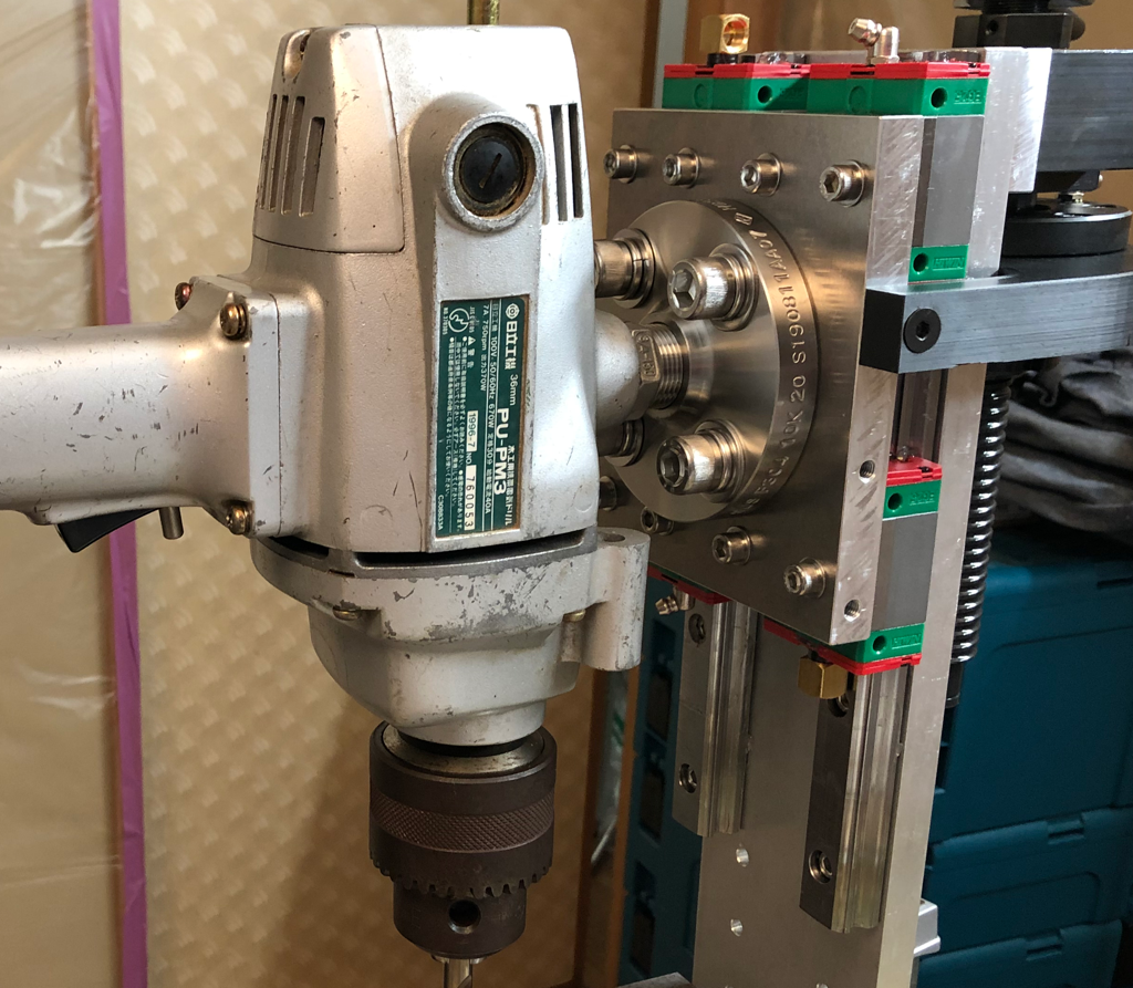
So when I saw this oddity show up at a shop in the far northern Island of Hokkaido at $50, I thought it was worth the chance. I couldn't tell much about it from the pictures or the description (it was clear they had no idea what it was) but I suspected (and still do) that it was a Wire EDM (Electric Discharge Machining) drill head, made from domestically sourced parts, likely by a smaller manufacturer. EDM uses a high voltage sacrificial brass or carbon 'tool' in a non-conductive bath to basically precisely erode conductive metals, they either use a continuously moving wire (Wire EDM) to 
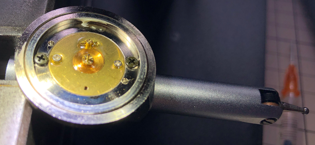
slice through metal, or they can plunge a shaped die or rod to create a precisely shaped pocket or hole. I suspected this device was used in EDM because the motor and belt were so undersized and there was a conspicuous conductive shoe at the top of the spindle. But what made this special to me was that the spindle part looked ridiculously overbuilt for the application, like the manufacturer needed something off the shelf and the only thing available at the time in this size range was intended for a much harder life.

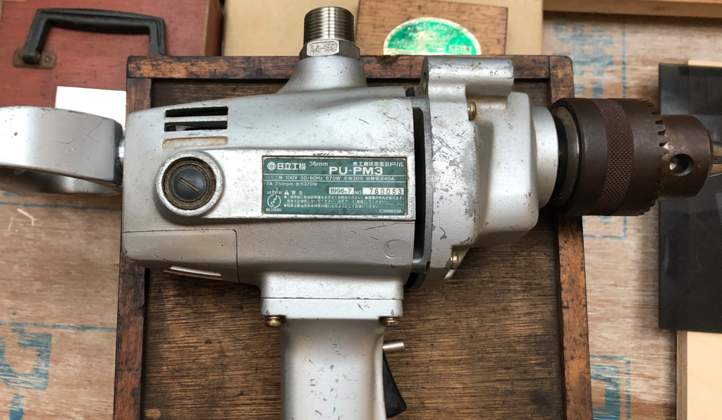
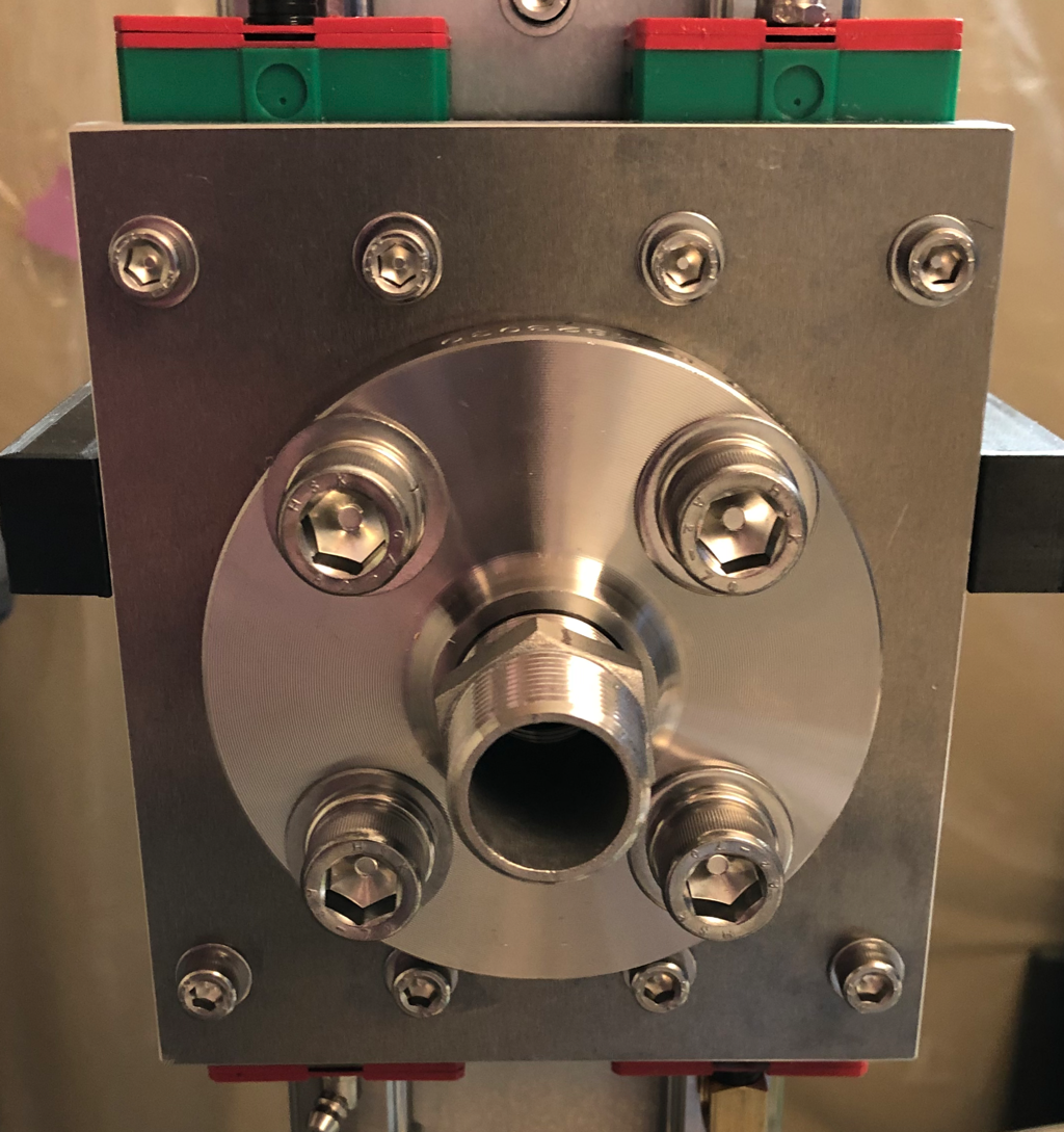
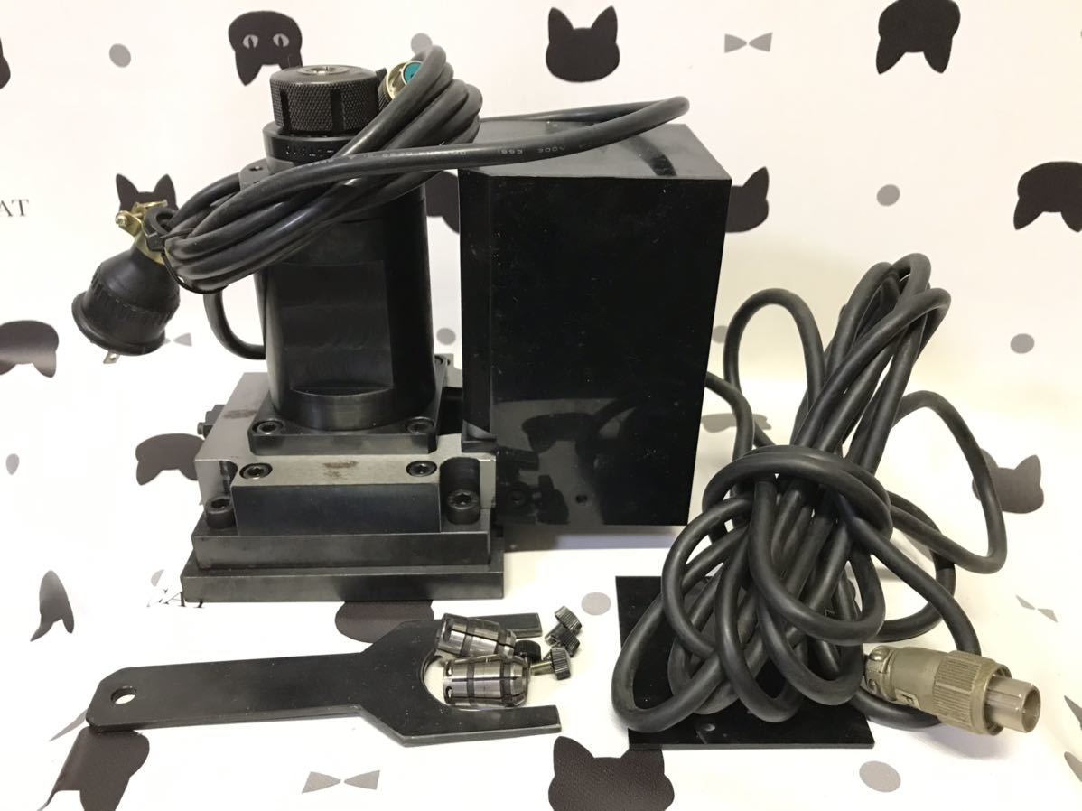
The only thing I knew was it used a Mizoguchi C10 collet system, a very rare but still supported collet chuck that can support 2.5mm - 10mm tooling. It came in a beefy wooden box (I'm a sucker for those as you all know by now) and used a tiny 60 watt DC brushed motor. I couldn't see the drive belt, and based on the lack of any controller and the "power cord" having a 110V plug on the end :oops:, I was pretty sure the motor was going to be toast.

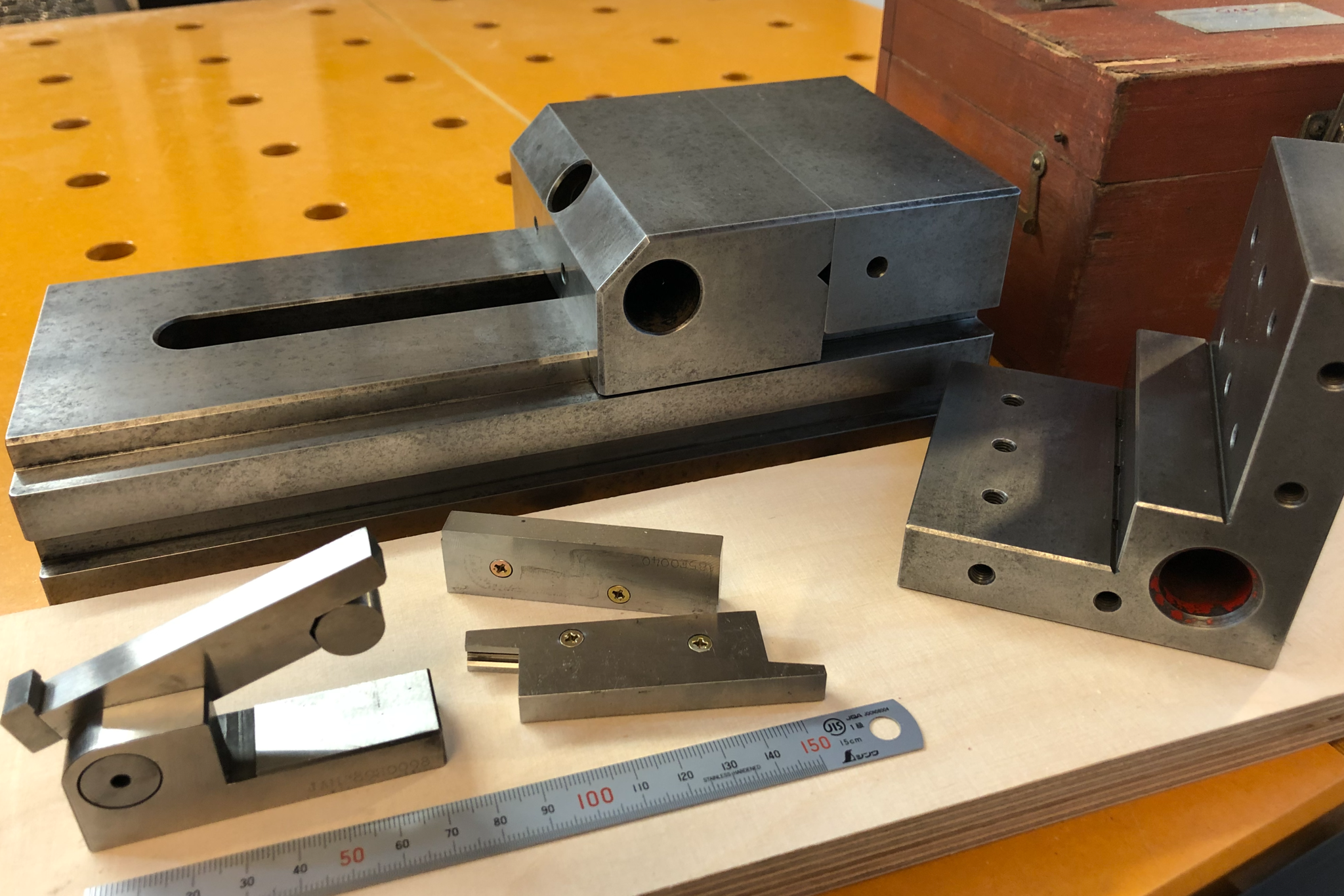
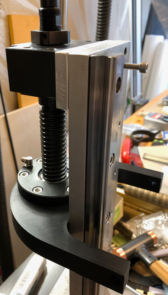
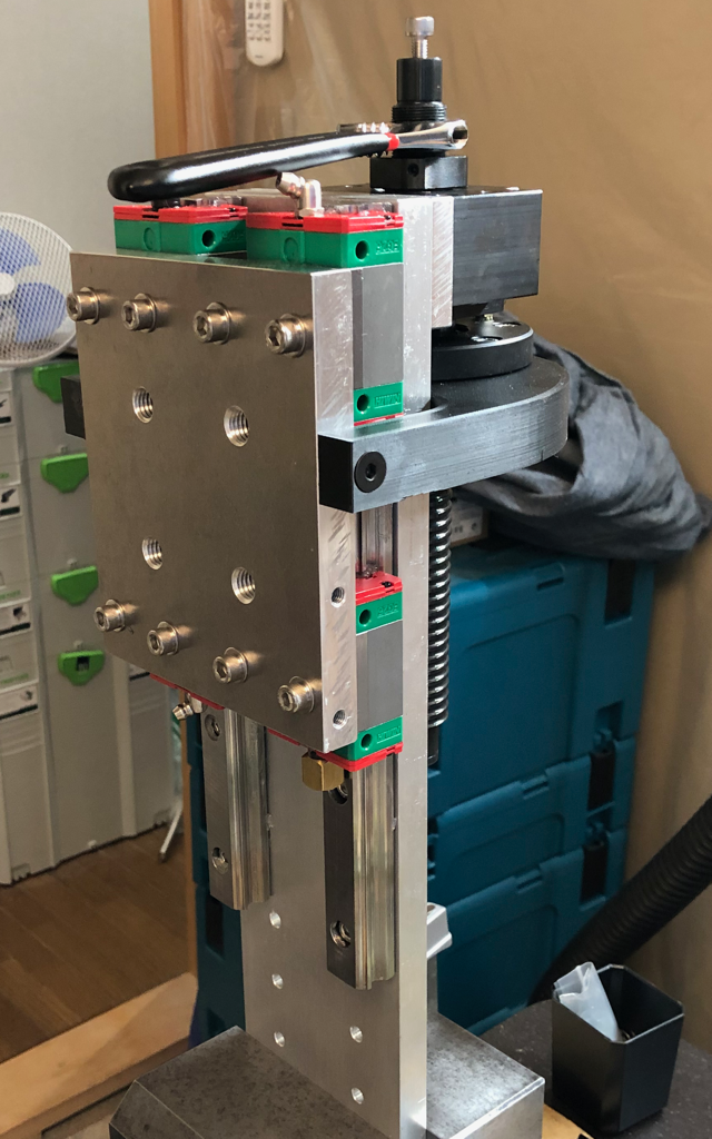
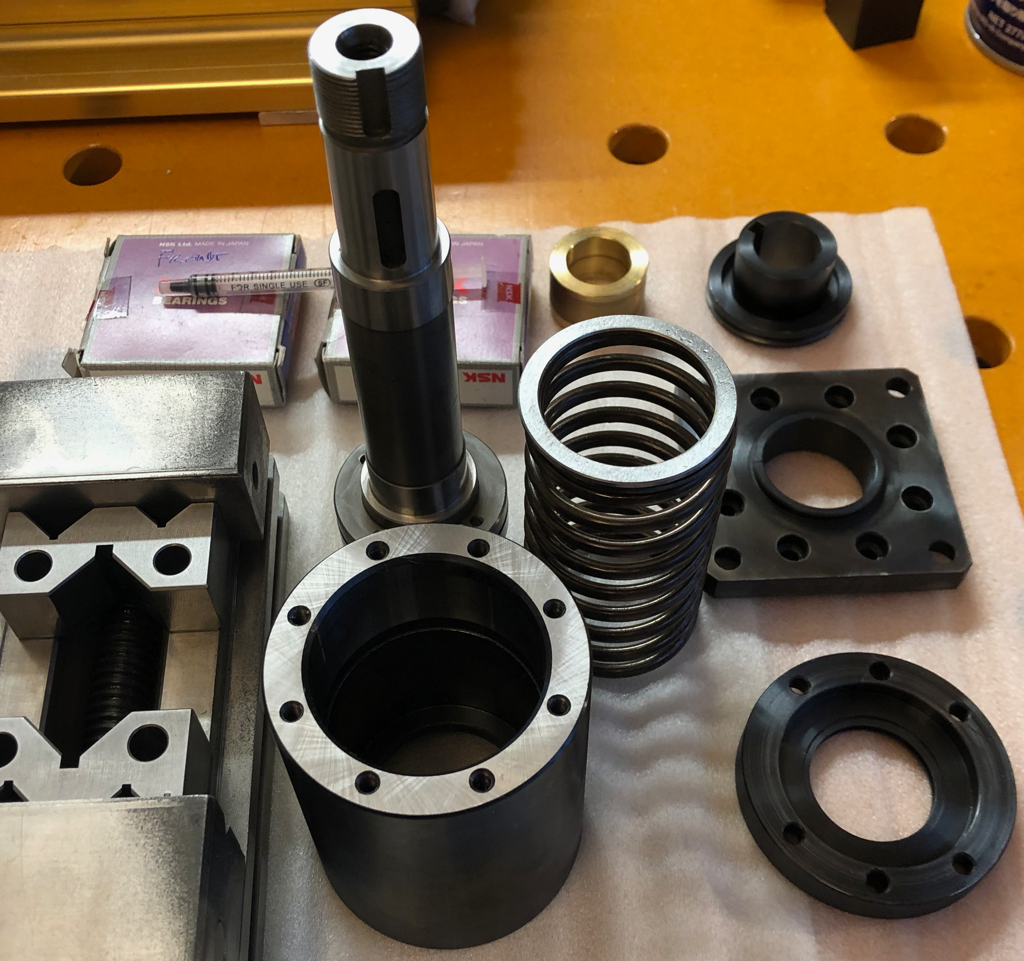
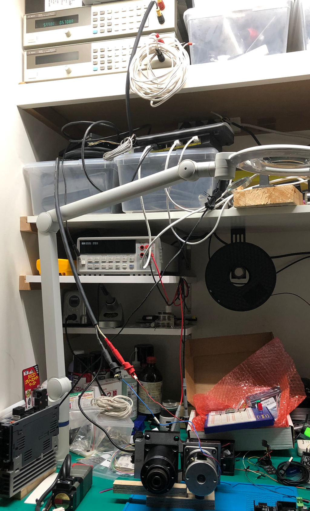
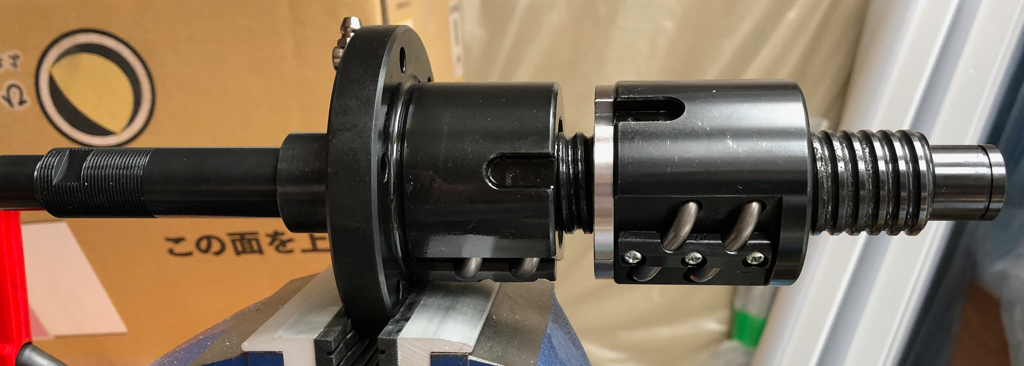
When the unit arrived, I was really pleased with the size and the solidity of the compact unit. It was all machined out of steel and well designed, it was a dense lump of goodness. The motor didn't smell of dead pixies, and a quick impedance test looked sane, so I hooked it up to one of my trusty Agilent DC lab power supplies and gave it a bit-o-juice. It spun right up, but the distinctive grumble of bad bearings told the sad story of why this little guy got abandoned at some second hand shop in the middle of nowhere... grabbing the poor tyke by the chuck I could slop it around at least a few millimeters, not good.

One of the great things about paying so little for stuff is it lowers the barrier to, "Let's see if we can fix this" which has always been pretty low for me. But what I do know about rebuilding spindles is that it is really easy to bork them hard, and it is not really something for the home player. But $50 right? It was hosed anyway... The first step was to identify the existing bearings, so I started the surgery. I was hoping to see at least a pair of angular contact bearings, the spindle shaft came out pretty easily, but the bearings looked like they were going to be a challenge. The front bearing was sandwiched between a front plate and the spindle body, removing the front plate left the bearing half exposed, but the outer race was blind set with no way to get behind it to pull it. The rear one seemed even worse, it was deeply inset into the spindle housing, and again it didn't seem like one could access the outer race to press it out. I could see the markings were both inward facing, but readable.

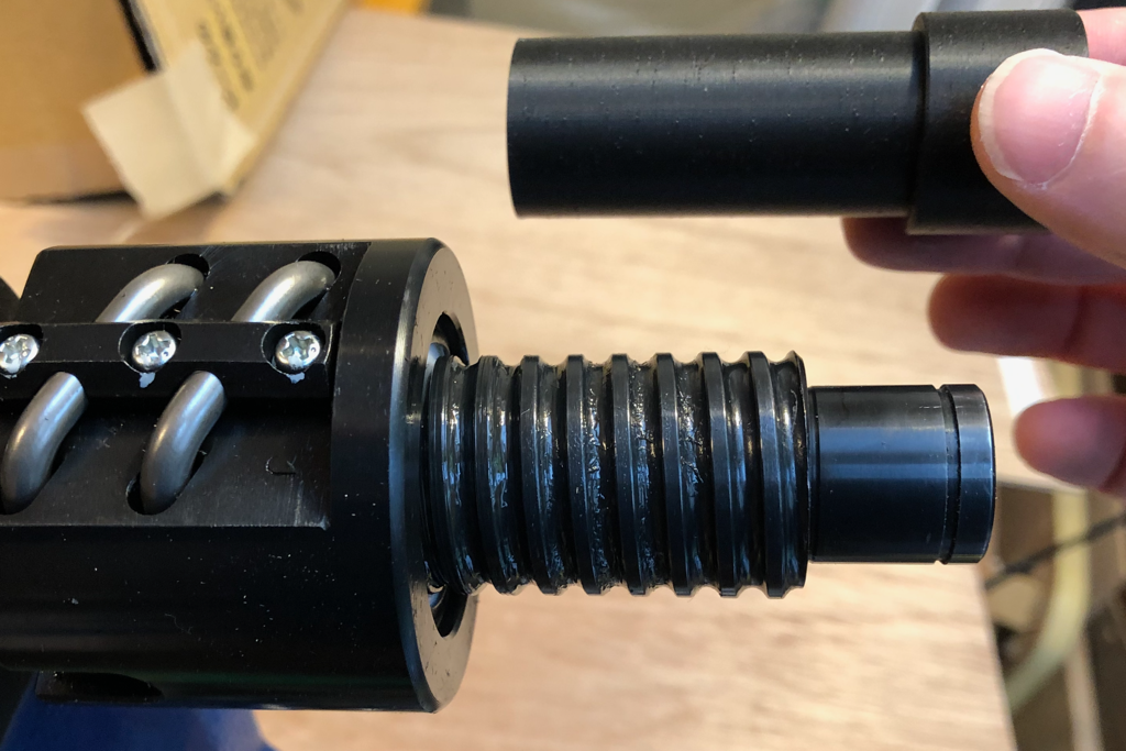
The inside wall of the spindle seemed to have this deep rounded threading, I was confused about the purpose of it thinking that maybe there was some kind of nut threaded on the inside that supported the rear bearing, but poking it with my fingers trying to grok its purpose led to quite a surprise when it moved! It was a giant spring in there... Now that was really odd, time to break out the Google who promptly informed me that this was a known design methodology that allowed for constant preload under high heat conditions for high speed spindles. It meant that the rear bearing was just interference fit and I should be able to gently tap it out with a brass rod inserted through the front bearing opening. It came right out along with the thick spring and a thin spacer. This left me with the front bearing, which now that the rest of the spindle was disassembled was clearly inaccessible from the back due to the lip it seated against blocking any chance of reaching the outer race.

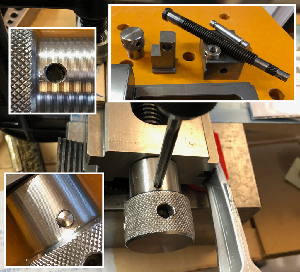
The bearing was shot anyway, so I tried to tap it out using the inner race, but the wear made it even easier to just puke its bearings all over the floor, time for a plan B. The good thing was there was a few mm protruding from the housing, but none of my various pliers or vices could get an effective grip, or get it to budge at all. I told Nailmaker to "shut the eff up", and went to the biggest hammer in Mickey's Toolbox, the dremel, a Proxxon flavored one, and ground slots around the edge to get some purchase for the blade of a screwdriver. I gently worked my way around the edge and finally got it pulled.

bearing.png

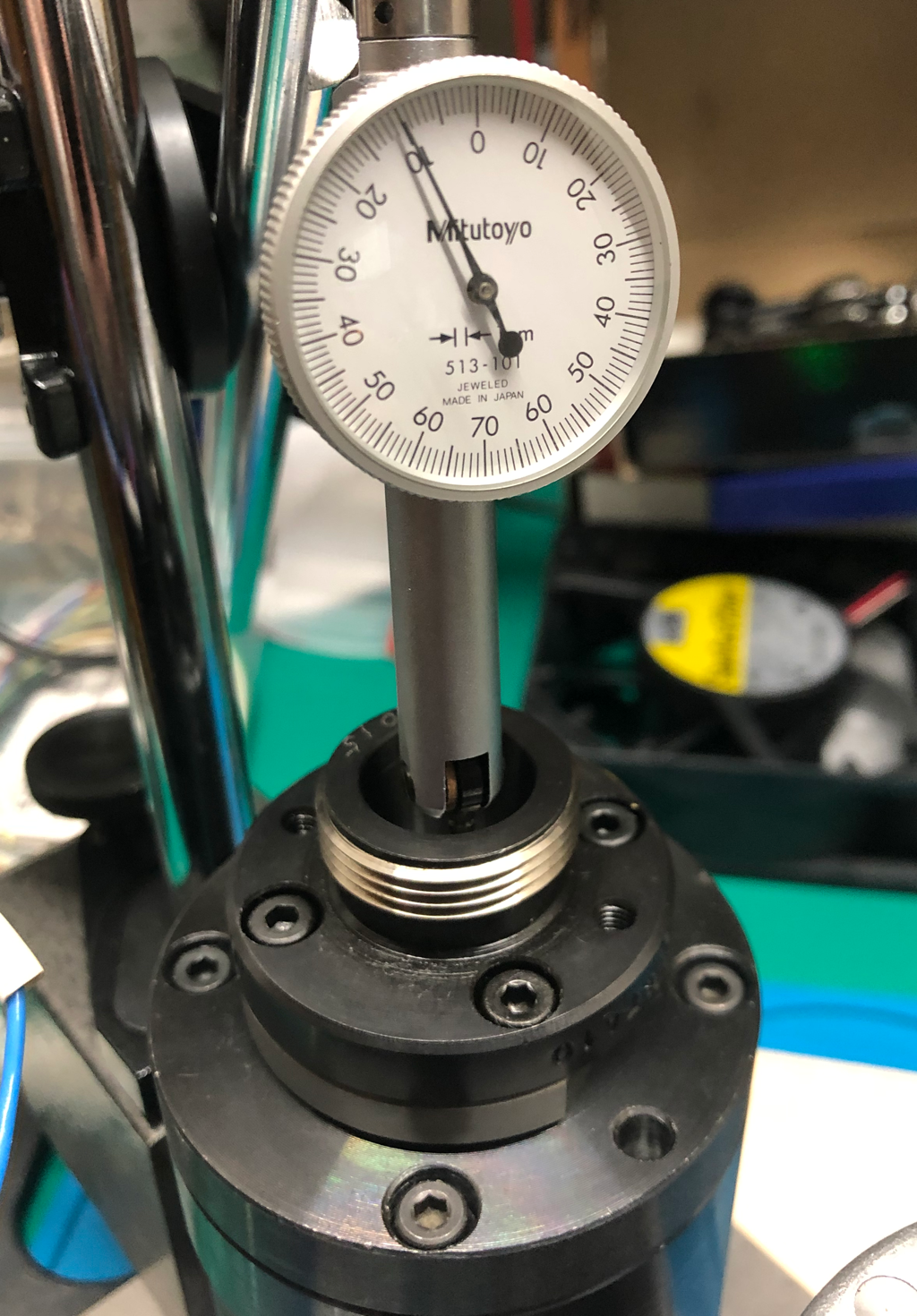
(Removed and reassembled)

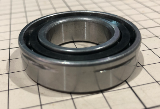
The bearings were 7005 P5 angular contact bearings. P5 is the lowest grade to still be considered precision, but still likely overkill for what it was doing. My favorite surplus shop had one pair for sale for $20, they arrived the next day, now the real preparation was to begin. The reason I was psyching myself up so much was I had seen several spindle rebuilds by my YouTube Guru's and I knew there was a lot more to it than it seemed. I also didn't have one of the key tools, a (hydraulic) Press, so I was going to be very dependant on luck and thermal manipulation.

spindle_2.png

I had the bearings, but I didn't have the special 
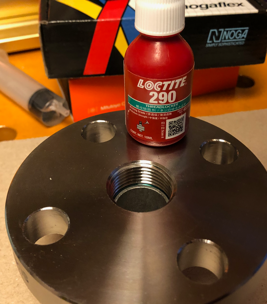
high speed bearing grease that is required to make these bearings last for any useful amount of time. The go-to grease for high speed spindle bearings is German Klueber Isoflex NBU 15 but the smallest amount I could find domestically was 400 grams for about $200, which wasn't going to work for me. A lot of research brought me to a domestic product, 
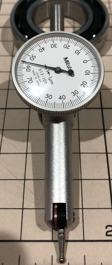
Sumitec SG 402 that I could get in a reasonable 80g tube for under $30. I had to do all the calculations for the precise amount to pack in each bearing based on expected speeds and loads (3.5ml/ea.) and carefully applied it to the bearings inside a fresh plastic bag to keep it as clean as possible.

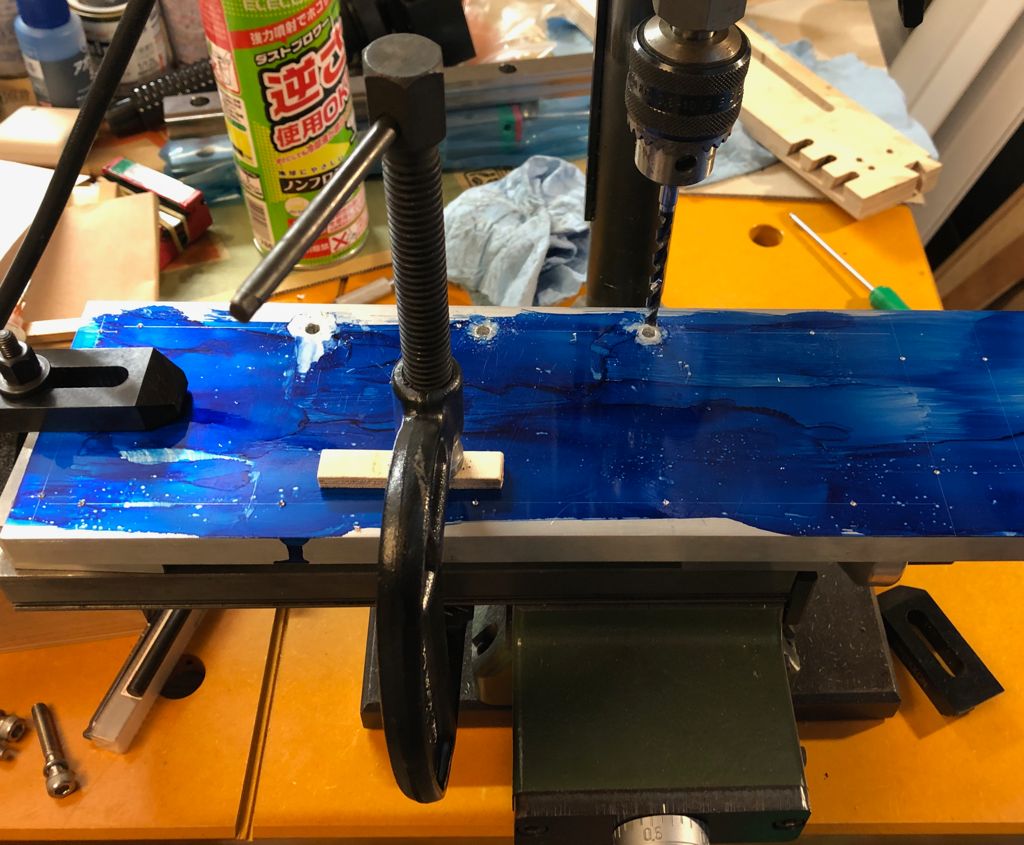
Next I carefully cleaned all the parts, gently wrapped the main housing and front plate in aluminum foil and put them in my toaster oven set at 120C. The front bearing and the spindle shaft were wrapped in plastic film and went into a cooler with some dry ice. I had a big plastic bag I inflated and put a ton of desiccant into.

spindle_3.png

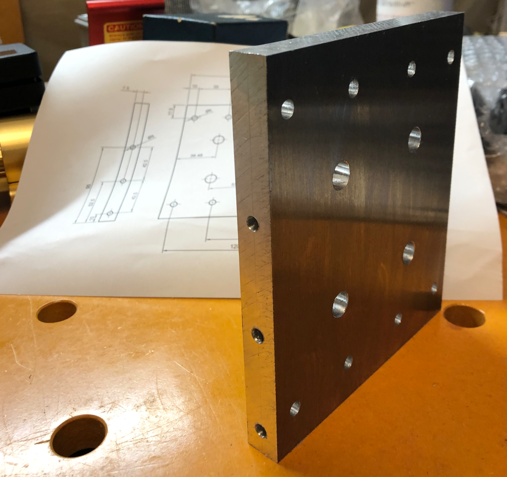
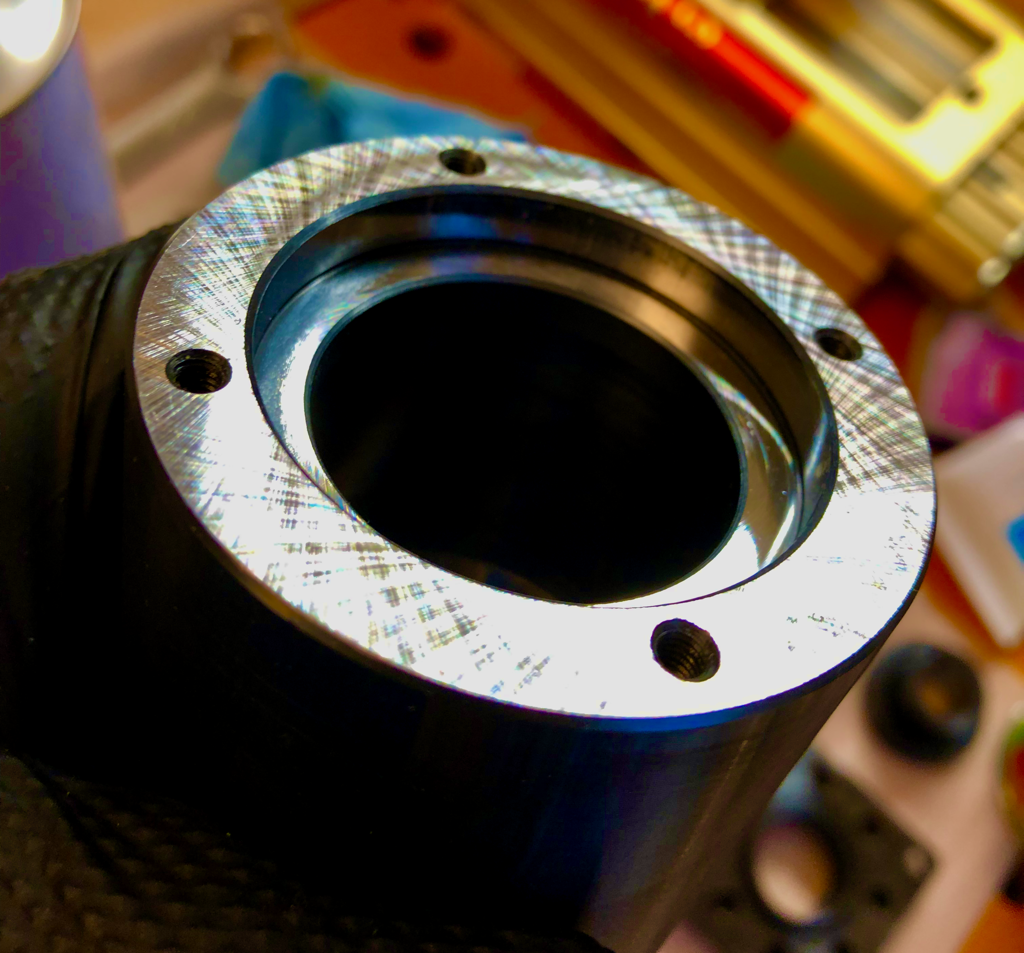
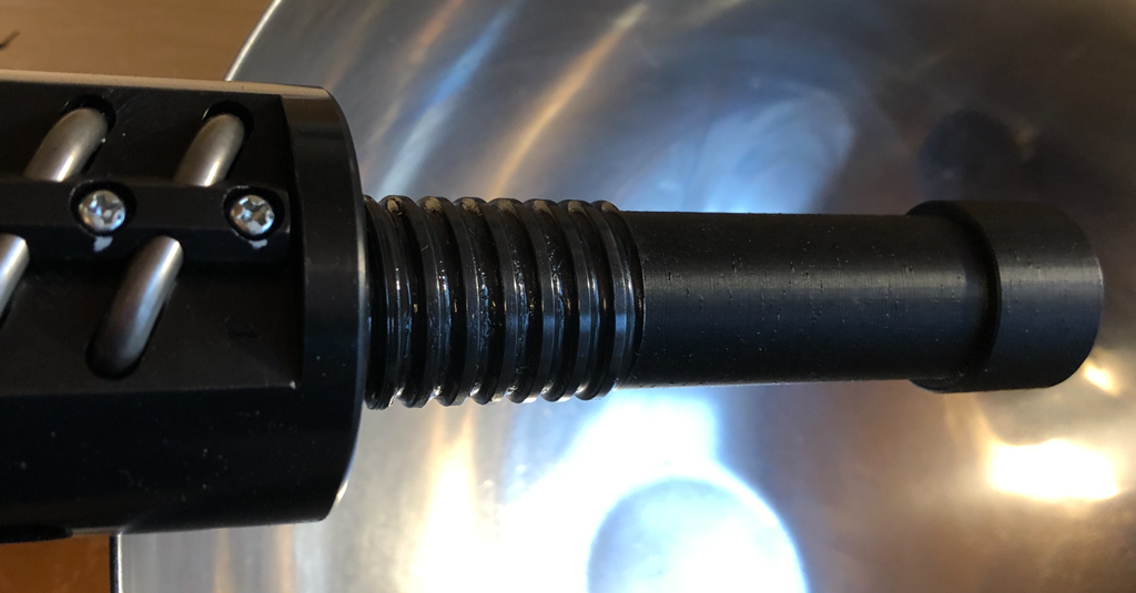
(That crosshatch ground surface is love at first sight...)

With the housing expanded by the heat and the bearing shrunk by the cold, I could place them in the bag full of dessicant (to keep ice from quickly forming on the cold bearing) and unwrapped the bearing and plopped it easily into the housing, with the top plate quickly following. Then that assembly was put back into the oven to warm up the bearing too, and I repeated the procedure, inserting the spindle shaft into the front bearing.

With the shaft still cold and the outer housing too hot to touch without my welding gloves, I inserted the spring and the spacer and then placed the rear bearing (at room temperature) over the cold shaft and using the rear nut and a shim I started seating the bearing into the housing. All of this had to happen quickly, I was fighting the temps rapidly converging towards room temperature and didn't want to get anything placed in the wrong position, a cocked bearing that then has the shaft expand is nightmare fuel. Looking at everything proceeding exactly as planned I notice 7005 on the rear bearing and a cold chill fills my heart. I was sure I placed it in correctly, these angular contact bearings have a front and a back and they put all the makings on one side to make sure you orient them correctly, but here was 7005 sitting there staring me in the face, and the shaft was warming up, and the body was cooling down. Panic set in.
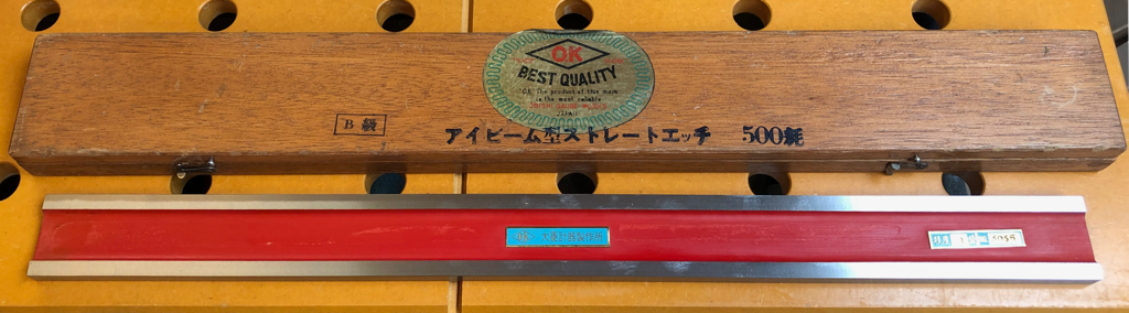
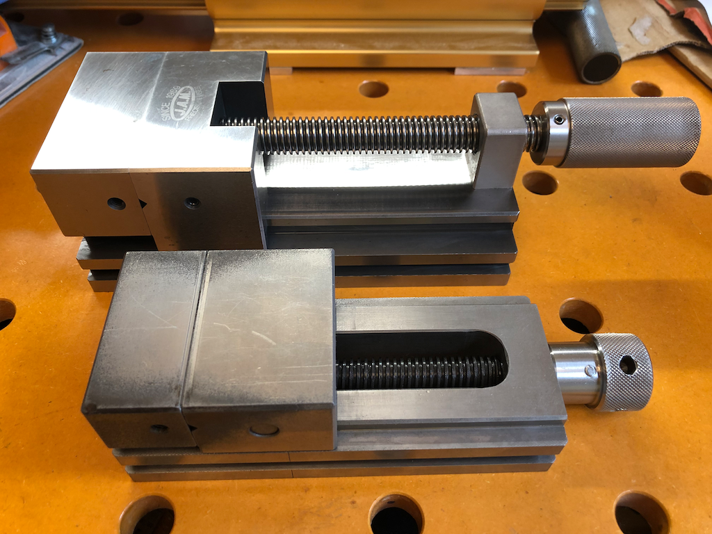
 
Last edited:

WheelsNT

Well-known member
Joined
May 8, 2008
Messages
77
Oh, the cliffhanger! “Is the bearing in there correctly? If it’s not, will he have time to get it back out before it warms up too much? Tune in next week to find out what happens!”
 
OP
B

Bakafish

Well-known member
Joined
Feb 7, 2017
Messages
477
Location
Tokyo
Oh, the cliffhanger! “Is the bearing in there correctly? If it’s not, will he have time to get it back out before it warms up too much? Tune in next week to find out what happens!”
Heh, I started to get nervous about the maximum post length and was right at this spot... felt like a natural stopping point :p
 
OP
B

Bakafish

Well-known member
Joined
Feb 7, 2017
Messages
477
Location
Tokyo
@Ryan upped the max post length to 30k characters (see this post). I counted yours at 11,700 (including a bunch of whitespace).
Excellent info. Inspecting a guy's whitespace is tantamount to stalking though... 😜

micron_0.png


Today was spent cleaning and lubricating this second hand Mitutoyo pocket Test Indicator. A good price, but when I tried to use it I found it was a bit sticky when measuring deviations under a few microns, which was exactly what I bought it to do. I didn't document the cleanup as I was in the focus zone and I'm not experienced at doing this sort of work. There really isn't a lot of documentation out there, but I found a exploded parts drawing and from that had a baseline of confidence I knew where all the parts were.

micron.png


It was an impulse buy, and after I determined it wasn't healthy I discovered the fact that is is a pretty old pooch and Mitutoyo no longer does service and support on it. So it was either going to be useless as it was, or be put down by my hands (in service of SCIENCE!) with a small chance that I could breathe a few more moments of life into the lad.

I have to say, the mechanism wasn't complex, it wasn't an easy job, but the average pocket watch would likely have 10 times the parts. The biggest challenges were getting the initial plastic 'crystal' and bezel off, then getting the needle removed. Both of which were done with plastic spudgers and felt like I was 100% going to break it until it complied uneventfully to my persuasion. Then I flushed everything with IPA and some special degreaser. The hairspring pictured above was most likely the culprit, it seemed to stick to itself and not really move consistently, so I just kept flushing it until it got symmetrical and lively.

Unscrewing the four screws exposed the main gearing, I cleaned it and put a needle point amount of watch oil on the two ruby bushings in there, there was one more ruby bushing on the back side if the shaft for the indicator needle, it had some deposits on it that I carefully scraped away with an acupuncture needle, using one of those Andonstar digital microscopes to get a good look at what I was doing. It was a great help...

Finally I cleaned and greased the outer bezel slide with some thick camera lense grease I had from rebuilding my wife's Olympus medical scope last year. It gives it that smooth professional feel, nothing beats having the right solution... I screwed and tapped it all back together, carefully aligning all the little gears so it moved freely, but hopefully without any slop. It seems to work well now, I will need to check it out again with my gauge blocks and the monster 0.5 micron Digimatic reference meter.

Anyway, I will resume the spindle story soon. But I got the hand wheel for the Mag-Drill project today (I paid $3, not intended for machinery, but I think a perfect fit for this Frankenstein build) and I will need to get to work finishing up that project tomorrow.
 

zanyad

ALLIANCE MEMBER
Joined
Apr 26, 2018
Messages
2,755
Location
NE Ohio
Excellent info. Inspecting a guy's whitespace is tantamount to stalking though... 😜
Pfft. :spit:

It's all here in the page's code. Not sure how much the whitespace counts, or whether any is added by the xenforo system.
 
OP
B

Bakafish

Well-known member
Joined
Feb 7, 2017
Messages
477
Location
Tokyo
I left off explaining my panicked state looking down at the clearly marked 7005 on the inner bearing race, and freaking out that I had inserted it backwards. This fear was being compounded by the fact that the rear bearing wasn't fully seated, since I had not yet torqued the center hub and that was causing some strange preload and interference with the back plate, and everything was still at extreme temps so the rotation felt wrong. I figured it was better to be safe than sorry, and so I pulled the shaft while I still could do so without doing serious damage to the new bearings (I hope.) I inserted a brass rod through the front bearing's inner race and made sure it was positioned to only contact with the rear bearing's outer race and proceeded to work my way around the edge. Using the weight of the entire, still piping hot, outer housing I gently tapped the brass rod sticking out the front against my heavy vise. I was carefully observing my progress when, BANG!

In my panic I had completely forgotten that the preload spring was still potentially doing its thing and the bearing came out of there like a stuck pig and smacked me square in the nose. The spacer shim likewise buggered off to the nether regions somewhere, I only heard a pinging sound as it buried itself in dust in a dark inaccessible corner of my work area. It was a significant blow, three days later there is still a red mark on the bridge of my nose, and to add insult, the bearing had been inserted correctly the whole time. There was a great deal more text printed on the other side. Had I paid a little more attention when I was packing them I would have noticed that they helpfully labeled the bearing number on both sides, but I was so busy trying to keep everything clean I'd been working on them inside a bag and just never saw the small numbers there. Over an hour of searching finally located the wayward spacer, cheekily suspended by the surface tension of the grease layer to a piece of the thin plastic film I have protecting the walls from contamination of my work. By that time the housing was back up to temperature, the spindle had chilled down, and with a lot more respect for the spring's right cross, I got the shaft and rear bearing seated again and waited for everything to get back to room temperature so I could torque all the screws.

spindle_4.png


The next morning I reattached it to the motor plate and started it off at low speeds on the healing bench to start to run in the bearings. The change over the old ones was dramatic, with everything being extremely tight and quiet, no more grinding and slop. As I mentioned, the motor isn't really designed for the speeds this spindle can support, the bearings are rated for about 22k RPM and the constant preload spring design is made specifically for the heat generation of high speeds, so the maximum of about 2000 RPM I can get with this motor and belt reduction is not really able to get these bearing properly broken in. It is possibly why the original ones went bad in the first place, that or high voltages somehow leaking through the bearings which is a really quick way of destroying them. There just wasn't enough wear and tear on anything else to explain why the original bearings had gone bad... it will be interesting to see how she holds up over time.

spindle_5.png


I measured the runout with a number of different indicators, they all saw the same 10 microns at the collet and 12 microns on a 10mm end mill about 30mm out (although I only hand torqued the collet as I need to get a wrench for it and find out how tight I should go.) I was honestly hoping and expecting a lower runout number, but between my complete inexperience, P5 grade bearings and the spindle not being broken in (and possibly not enough preload), I suppose it could have been much worse. Now I need to figure out what kind of motor to get and how to couple it, either a beefier timing belt or direct drive. A brushless DC 18v Makita trim router goes from 15k - 30k RPM and with little bit of gear reduction would probably be a cost effective choice. It just feels bad to buy a new one just to break it down into parts... I will also need a honking big hi amperage DC PSU, so I guess around $500-600 total, not cheap unless it works really well. It would also represent my fourth router, and I worry that that might trigger some form of intervention...
 
OP
B

Bakafish

Well-known member
Joined
Feb 7, 2017
Messages
477
Location
Tokyo
I ended up ordering a Brushless DC motor system out of China. I paid about half the total price for shipping and tariffs/taxes, so it wasn't really as cheap as it seemed on its face, but I'm still hopeful that it is a workable drive. More on that once it arrives in the next few days.

I also picked up an old cast iron surface plate that I weill use as the base of my CNC.

pl_bottom.png

I think it was buried for a few years based on the lack of paint and the solidity of the grime underneath it. I used a wire brush on one of my angle grinders to clear off the worst of the grime and then doused in in WD40 to soak for a while. I'll do another pass with wire wheels and then degrease it before priming and painting it. I haven't really inspected the top surface, I don't need it to be all that perfect, I can scrape it where I will attach the aluminum extrusions. It weighs a hefty 70 kilograms, but will be lighter than using a granite plate and given the cost ($150 delivered) and condition I won't feel terrible drilling holes in it for fixturing and the CNC frame.

I have been trying to wean myself off of the auction sites, I've tried to stick to my list of needs and not get too distracted by various 'great deals' which is really hard and not entirely successful. I've bought more vises :cautious: I'll spare you the details. One thing that's been on my wishlist for a long time is one of these.

kuroda.png

This is a Kuroda Precision UFB-2 boring/facing head. It is a little clockwork device used to make precision bores, counterbores, grooves and for facing operations. It has a set of planetary gears with various worm drives and adjustable releases that allows you to mechanically set it to traverse across two points. It was manufactured under license here in Japan, there are German made WOHLHAUPTER units that are identical, I think they may be the original, although I haven't really done all the research on who created them. Wohlhaupter still makes the larger versions, this is the second smallest, there is a very rare #1 size (that Stefan Gotteswinter has) and the #3 and #4 sizes are the most popular due to their more practical size for big mills. I was looking for a #2 as it seemed the most prudent for a small shop, and I was able to pick this one up for under $150. I disassembled and cleaned it earlier today, and it is in great shape, so I'm really happy. I bought a second one for a few accessory parts as it was a more complete kit including the often missing end stops, but the main unit is in much worse shape, so after I service it I will post the condition in the for sale area in case someone wants one for their collection.

Lastly, the drill project is almost finished, I used it to drill some nice big holes in thick Aluminum and it did great. I added another missing component to make it complete, I will post about it soon.
 
Last edited:
OP
B

Bakafish

Well-known member
Joined
Feb 7, 2017
Messages
477
Location
Tokyo
I bought another vise.

I know, you're not at all surprised by that. I guess I shouldn't be either... it had a wood box, it was $50, it was a JAM. I keep telling myself they will come in handy, at least the wife can use them to weigh down my body after she kills me for filling the house with vises.

The spare Kuroda boring head I bought for parts turned out to be the slightly larger UFB-3 model, so everything was completely incompatible with the little UFB-2. From the photos it was really difficult to read the markings and other than scale they look identical. The seller didn't really know what it was and didn't post the model number, and based on the price and the grime covered M12 which I misread as MT2 or Morse Taper 2, which would have confirmed it to be the smaller unit. It was really bad in the pictures,it was being sold as "junk" but like many of my recent purchases it turned out to be a jewel in the rough. I did a full disassembly and soaked everything in IPA. A bit of scotch brite scrubbing brought it back to shiny, other than the grime layer it had very few signs of actual use, everything was tight and smooth. I carefully cleaned and lubed all the components. Between Stefan and the cheerful Finnish machinist Finno Ugric Machining I had the confidence to rebuild these little machines for machines.

kuroda_2.png

Everything, including the box was steeped in old machine oil and grinding dust. I used Simple Green and warm water to wash everything, transferring it into a small pail of IPA. I removed all the felt and fittings from the box and scrubbed it until I reached the thin black lacquer all these old wooden tool boxes seem to be painted with. I will re-felt it and replace the rusty clasps and hinges. The accessories were the main reason to buy it, and although they won't fit the little guy, they were much more complete. After cleanup it looked far better than the units being sold for 2-3 times the price, and I think these units are already going below market value over here.

kuroda_3.png

Cleaned up nicely...

I've got to finish the PBX and IP phones for my wife's clinic, so I have to stop cleaning tools I can't even use. I'll try to finish off detailing the Mag-less(?) drill project though. I know I keep promising.
 
OP
B

Bakafish

Well-known member
Joined
Feb 7, 2017
Messages
477
Location
Tokyo
Nice salvage work. Those are gorgeous. Where's the mill?
Great question. The truth is, the initial spindle I am using (Mizoguchi C10 collet system) on the yet to be built CNC is only able to handle small 10mm and under tooling. My mini-mill is similarly limited, and my mini-lathe has an MT2 tailstock, which was where I figured I could get a bit of use from the first one I bought, for precision boring from the tailstock. It is likely that I will move to a larger spindle setup if the CNC proves to be sturdy enough, and it is possible that I'll even be able to use the bigger model if everything turns out, but for now I'm embarrassed to admit that they are pretty much machinist jewelry...

The larger head was an accident, and now that I have cleaned it up and become intimate with its inner workings, I loathe the thought of parting with it. I'm still hoping that I can find my niche to create a business of some form (leveraging the yet to be built CNC), and that would give me a good excuse to retire from IT and potentially get a 'real' shop and possibly a more traditional mill. We've been thinking about negotiating with the neighbor to buy the much larger property next door (which is only made possible by my wife's hard work I should add) which we could develop into a small apartment complex and I could have some private basement space allocated for my projects.

It's a flimsy reason to justify owning these little beauties, a large part of me just wanted to have one once I learned about them, but at least they won't be rusting away under my care. I don't understand how people can spend thousands of dollars on things and then just let them corrode away caked in filth. If they used them until they broke I could at least understand that someone was sacrificing them on the altar of production, but so many of the items I've been buying have just been neglected and seem otherwise unmolested by actual use.
 
OP
B

Bakafish

Well-known member
Joined
Feb 7, 2017
Messages
477
Location
Tokyo
There was a break in the summer rainy season today, so I took advantage of the brief bit of sunshine to do a final scrub of the cast iron surface plate. The sides were still very encrusted, but because they were machined relatively smooth I could use a sharp scraper to get off the bulk of the congealed years of crud. The bottom cavities had been wire brushed, scraped, soaked and vacuumed multiple times. It really needed a good sandblasting, but I am still compressorless and my main goal is to keep this from rusting and keeping it from dumping a ton of **** everywhere when moved inside, so I had to draw the line well short of perfect. More wire wheeling and IPA scrubbing while I fought off the mosquitoes and I got it down to what I hope was bare enough proportion of metal to allow the paint to stick.

I wanted to use some kind of thick and durable machine paint that I could brush on due to the complex and rough shape of the underside of the plate. But it was really difficult to find anything that wasn't in sold in too large a quantity, undocumented on how to use it and/or ridiculously expensive. I've found paint to be one of those arcane arts that gets even more complicated for me here due to language corruption of western nomenclature and locally traditional 'best practices' that are poorly documented or at least hard for me to discover. I ended up using a spray on rust preventing primer I had used previously (for the angle iron rails in the pantry project) and an unusual 'weak solvent type 2-part urethane spray' that implied it was very durable and chemically resistant. You break an internal seal with the spray lever and then mix the two parts in the can before applying it, something I hadn't used before. It seemed to work well enough, it will be interesting to see how well it adhered and how it does long term.

pl_painted.png

I chose a fairly traditional blue and painted the external sides since this will never be used as a surface plate again. I'm going to let the paint cure for a few weeks outside under my eaves while I add some bracing for the table it will be moved to (and mentally prepare for placing it where it can potentially crush me.) The thing is supposed to be 150 pounds, but it feels even heavier. The top surface still needs a full scrub and polish. I have a hand scraper that I may attempt to use for the surfaces where the two main extrusions of the CNC will attach. The idea is that the top of this will be the reference plane that I can build everything squarely off of. The top surface should be flat enough, but I'll know more when I finally get it moved inside and I can take some measurements.

This was a lot more tedious than I expected, but I never would have paid for a new cast iron plate this size. The alternative would have been Aluminum extrusions that would have been more expensive, less strong, more difficult to align and poorly damped, so my outlook is currently still positive overall.
 

Motoman1100

Well-known member
Joined
Oct 2, 2014
Messages
443
Location
GA
This is definitely one of my favorite threads. When I was going through the latest post I just kept thinking that it's probably a really good thing you dont have a large garage.... it would be so full! Ha! Thanks for posting such great pictures and descriptions.
 
OP
B

Bakafish

Well-known member
Joined
Feb 7, 2017
Messages
477
Location
Tokyo
I finally got my second jab. The health care system here in Japan is light years ahead of what we had in the US in so many ways, the costs are so low you wouldn't believe how little they are compared to the states. It's a public system, with tight integration with businesses who ensure yearly full health screenings (free of course) and bigger companies have their own clinics and staff medical care workers. I get about $400 a year from my company to spend on "heath items" from an online health service, which has kept me up to date on the latest Apple Watches (offered at a significant discount) and a really well built blender (for wheatgrass or Margarita's? I think we all know...)

We are way behind the states in vaccination though. The Japanese are really never ready to accept the idea of an invasion, and despite the extensive health care infrastructure and experience with vaccine production, they were many months behind the Western world in getting people inoculated. So far the infection rate has been relatively low (although artificially depressed by difficulty in getting tested, you basically have to present as full blown, low Oxygen Covid before they will test you.) But Delta made it here about the same time everywhere else, and unsurprisingly there are a lot of anti vaxxers here too. Here in Tokyo, because of its vast size, unlike other prefectures we are subdivided into 23 "Special Wards" that are run a lot like counties are. Each one came up with their own system of distribution, following the national guidelines. In my ward they sent out vouchers in batches to the different age groups. Without a voucher you couldn't make an appointment. People quickly discovered that the voucher numbers were sequential and predictable and crashed the reservation system with illegitimate appointments, which caused further delays.

As I am old enough to be quite fearful of the Covid, but not old enough to be anywhere near the front of the line, I finally received my voucher. With excitement I logged in to the system I was astonished to discover that every appointment was filled for the next month. The system was so poorly implemented, you had to page through thousands of 'unavailable' appointments, looking for an open slot. And while it was logically broken down by location, there was no way to just look for the earliest available slot anywhere in the ward (I mean the ward's area is small enough that you are only a few miles away from anywhere...) So it took months, and some scares (my wife is a doctor who, although fully vaxxed early on, has been regularly exposed by patents) but I finally feel a little safer.

As far as my many projects are concerned. I've bought a ton more stuff of questionable utility, including at least 2 more vises... I added some reinforcements to my desk and key shelves to handle the weight of new equipment. The little granite surface plate I ordered arrived and sat in it's wooden crate in the entryway for a month. My wife never even bothered to ask me what it was, she's likely in some orthogonal form of denial of these things existence to my delusions of their need. I decided to get a new one, since the cost was reasonable and the accuracy was very high due to modern manufacturing. It is made by a Japanese company, but they manufacture it in China with Japanese machines and management. It's a small plate, 300mmx450mm, and the certification showed it is under a micron of deviation across the whole surface, which is pretty crazy.

surface_plate.png

It has this incredible satin shine to it, you really can see the flatness in the way it interacts with the light and it just feels so nice to touch. I already have inexperience to deal with, I didn't want to inject further uncertainty with an unknown reference, and the used ones in this size were not a lot cheaper. I will admit that the bigger plates at auction are pretty cheap, but without a real shop they are completely impractical.

I had a pretty brutal setback on the CNC project. I've been collecting parts, linear rails, ball screws and motors and motor drivers. I've been trying to keep it all as Japanese as possible, and one of my choices was to use Oriental Motors special closed loop stepper motor system. This is a very high end way of controlling movement, sharing many capabilities with true servo motor systems (at a similar cost though.) Being closed loop, the motors have a very sophisticated 'absolute' encoder in them that can detect 1800 increments per rotation. So the driver (the box that sends the higher voltage/amperage to the motor) knows exactly what the motor is doing at all times, and since it uses non-volatile memory it always knows exactly where it is, even if you power it off and move it. This is more useful than you might think. The ability of the stepper driver to know how the motor is responding to movement requests, and to be able to detect when it is not moving as fast as expected and momentarily increase power to help it succeed, creates a much more precision system. It will also halt everything if it is clear that you are asking it to do something beyond its capabilities. This can be the difference between a second chance to try a less aggressive cut and a completely ruined part. Most stepper based systems will just 'miss steps' when the motor can't make the motion and proceed along even though the cutting tool is nowhere near where the controller thinks it is, that's not great.

So I was really happy with my choice, and lucky enough to find a good selection of used and surplus motors and compatible stepper drivers (they are tightly integrated, you have to keep in the system.) The issue was that the stepper drivers come in several different variants, designed to support the different communication protocols in the machine automation market. The most basic control method, used by a lot of entry level to mid range machines is called "step and direction", and it is dependent on the fact that a stepper motor has a known number of steps per rotation (this can vary vastly, and is an interesting digression I will cover later.) So the Numeric Controller, the computer telling the CNC how to move all its axises in synchronicity, calculates the number of steps each motor needs to move in order to get to the next point in 3d space. These tiny vectors are just pumped out at a constant clock rate and it is up t he the stepper driver to turn the motors and get them to where they are supposed to go. It turns out that most of the units I've been collecting (7 of them) do not support this basic control method. They have 'internal controllers' that make them ideal for building machines that respond to basic inputs, but are really hard to use for a high speed externally controlled CNC. I thought they would work when I was buying them as the documentation for all the different models is somewhat unified and the limitations very poorly described, but it was a serious blow that sent me into a bit of a funk for a day or two.

I don't know about other people, but when I hit a problem I really have difficulty letting it go. If it isn't an impactful problem, I happily put it on my mental 'problems to solve' list where it may sit for months to be pulled out and pondered on, when I'm in the mood. But 'showstoppers' can really put me in a bad place, they are the kind of thing that will really get me intense and focused. This problem was completely solvable with money, it would cost me about $2400 to buy 4 of these stepper drivers new, but my pride and determination (and my desire to be a cheap *******) all drove me to research how I could get these things externally controlled in a functional manner. As is often the case with my most intense problems, they invade my sleep and I end up working on them even there. Like I said, two days of a glum chum, faced with trying to figure out how to get a controller using RS485 at 216kbps to do complex motion control. I hadn't spent thousands of dollars on these drivers and motors, but they would take thousands to replace with something of equal capabilities.

Then 4 of the units I needed, that I had never seen come up for auction before this day, showed up with a 'buy it now' price as if by the CNC gods will. I had all of them the next day for under $100. I'm not a man foolish enough to stay on the hard path when an easier solution presents itself, I'd love to tell you how I built a clever and unexpected hack, it may well have gone that way, it may still on a lower priority project sometime in the future. But for now I sleep soundly, knowing I have at least 4 working drivers and project Kaiju moves on.
 
OP
B

Bakafish

Well-known member
Joined
Feb 7, 2017
Messages
477
Location
Tokyo
I find it really difficult for me to not constantly make biological analogies when I think about how to explain the parts of my CNC project. I don't think it is particularly helpful since if I explain the function, the analogy is superfluous and likely kind of wrong anyway. I know a lot of you likely know more about what I'm talking about than I do, so forgive the remedial level that I am using, I've been trying to write with an unacquainted audience in mind, hopefully it's still worth your time. I want to get into more detail about some of the parts I chose and the thinking (or circumstances) behind those choices. A home-built CNC is limitless jumble of options, strategies and compromises, these posts are absolutely not intended to be an authoritative example or a how-to, I just want some company on my journey to share in the ups and downs with.

I mentioned above that I'm using somewhat unusual stepper motors and drivers. The more common stepper driver at the most basic level, is a device that converts low voltage motion signals coming into it from the controller, into higher current voltage that energizes the stepper motor's coils. Most stepper motors are "bi-polar" meaning they have two separate sets of coils and by changing the polarity of the two coils the driver can control the direction the motor moves, although because of the way steppers are designed they only move a tiny amount per change of polarity. By pulsing these small movements (steps) over and over again, an incremented larger rotational motion can be made. Keeping all the steppers coordinated and moving is the job of the controller.

There are a lot of different motion control systems, from the all-in-one cards used by 3D printers that have the stepper drivers built in, to full fledged PC based systems using the latest high power CPU's and custom PCI based interface cards. I mentioned in my last post that for most entry level systems step and direction signaling is used, and so the choice of controller is not as big of a commitment as many other decisions, since substituting one for another is mostly a challenge of reconfiguration not requiring any serious physical changes.

Many of the hobbyist CNC's use basic all-in-one cards like 3D printers, but instead of using 3D printer specific firmware like Marlin, Klipper or RepRap, they tend to use firmware based on GRBL which is an open source G-Code interpreter originally designed for Arduino boards and that has been specifically 'tuned' for CNC usage. Despite the significant overlap of the two different kinds of machines, 3D printer firmware has become quite optimized for that purpose and so there is significant deviation between the two.

G-Code is used by both CNC's and 3D printers, it's a very old standard that uses text based instructions to tell motion control systems what to do. A controller reads these commands (which are essentially shorthand for "move to this coordinate at this speed"), one line at a time, and converts them into the number of step pulses that each motor driver needs to get the machine to move to the coordinates specified. These Computerized Numerical Control (yep...) once required very powerful processors, but now tiny modern microcontrollers using ARM or similar CPUs are more than powerful enough to do this job at the speeds and precision basic machines require, and so I decided to start small and add the complexity and cost of a more powerful controller only if it became obvious it was required.

There are a lot of "packaged" prosumer level CNC controllers out there, but they are typically closed source and the better ones are rivaling full fledged PC based solutions as far as cost is concerned. Because my stepper drivers are so unusual I wanted to make sure I could take advantage of them, so being able to modify the code was important to me. I did a lot of searching and found a project called FluidNC that uses the Espressif ESP32 based microcontroller, a well established, quite powerful dual CPU microcontroller with built in WiFi and Bluetooth support that I've used for other projects in the past. This project was a fork of the original GRBL project, ported to the ESP32 architecture, and improved in several ways. One of the developers made an open source breakout board called the "Six-pack" that has built in support for up to 6 motion axises, and it supports 5 general purpose expansion slots for different I/O modules so you can customize it for your specific needs. I had him ship me one with a number of modules.

six_pack.png

One of the biggest limitations with the inexpensive microcontrollers used by these projects is that they lack enough inputs and outputs to control much more than a basic 3 axis machine. Each axis requires pins for 'enabled', 'step', 'direction' and at least one 'end-stop.' More sophisticated machines, with multiple end stop sensors per axis, coolant control, spindle speed adjustment, tool length and workpiece location probes, all while sending signals out to 6 stepper drivers synchronously, requires a lot more input and output pins than these devices can provide without some augmentation, and the way this issue was solved with the six-pack is borderline genius.

The ESP32 microcontroller has an astonishing amount of functionality built in, and one of the sub-systems is a pair of high quality digital audio signaling peripherals. Digital audio uses a very precise clock frequency (a CD uses 44.1kHz for example), coupled with up to 24 bits per waveform sample of information to turn music into a digital signal. The ESP32 can output such a digital audio signal over a standardized I2S data bus that is used by all sorts of devices to interchange those signals. Some clever ******* realized that by outputting a signal directly into a set of 'shift registers', a basic component used to buffer digital signals, they could create an extremely accurate way to synchronously send signals over a lot of parallel signaling pins. Basically, they repurposed the audio signaling architecture to create a high speed pulse generator to efficiently drive a buttload of stepper controllers using just the digital audio output of the microcontroller. The G-code is converted into steps, the steps are converted into a digital audio signal, that digital audio signal gets sent to the buffers, the buffers send the pulses to pins, the pins send the signal to the drivers, the drivers send the current to the motors, and the beast... it will shudder to life.
 
Last edited:
To avoid these ads, REGISTER NOW!
Top Bottom