To avoid these ads, REGISTER NOW!

Tooling organization

OP
L

lilscorpion

Well-known member
Joined
Mar 15, 2010
Messages
3,599
Location
Colorado
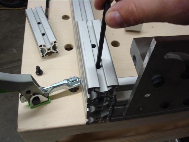
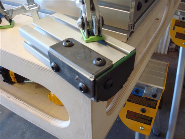
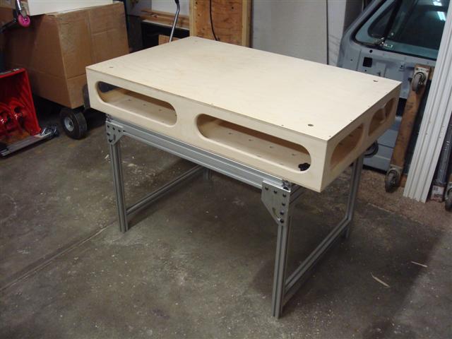
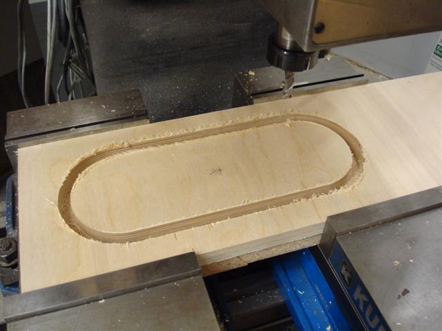
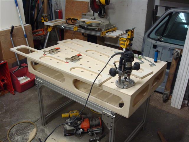
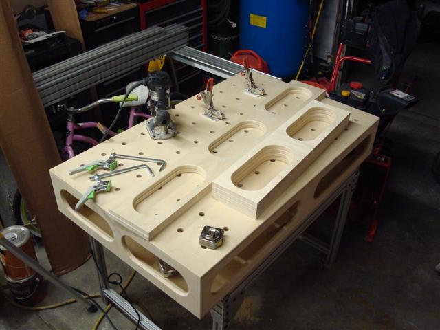
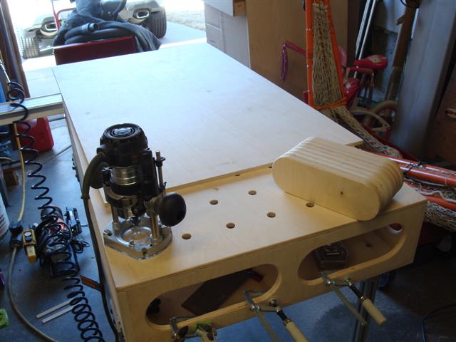
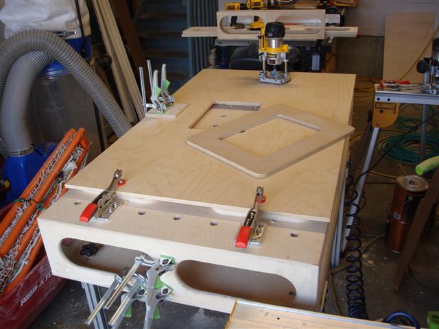
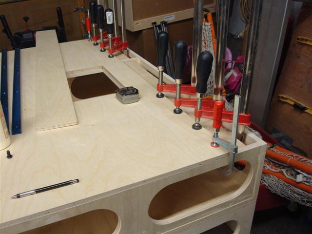
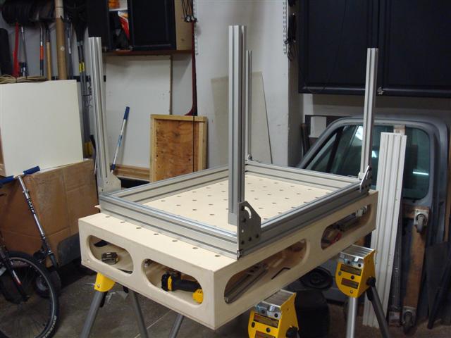
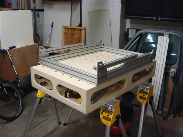
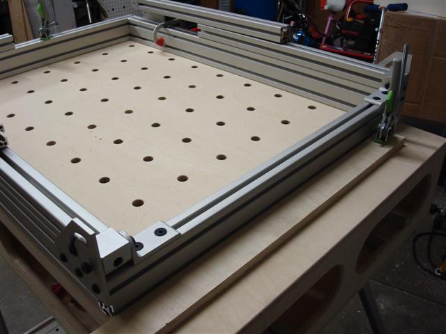
Work has been crazy which causes progress to be slow. It's making a project that should reasonably take 4 - 8 hours turn into one that lasts for weeks. Not having all of the parts here ready to go when I need them isn't helping. With the time I had today I swapped out the shorter brackets with the new pair I made which were designed to allow the legs, when folded, to stack nicely on top of the other legs. Now they nicely stack with no interference like I'd hoped.

MFT27.25.JPG


MFT27.50.JPG


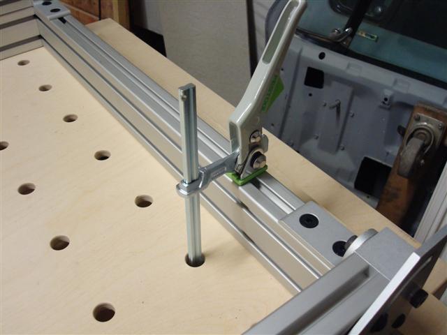
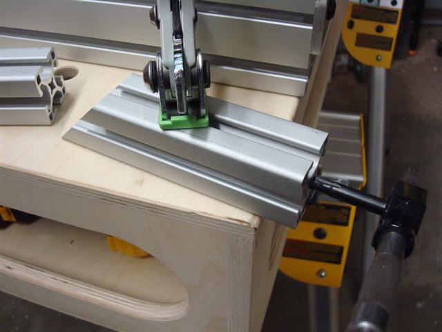
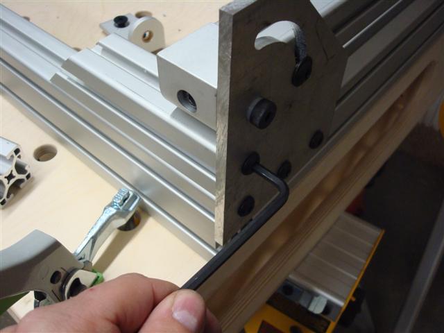
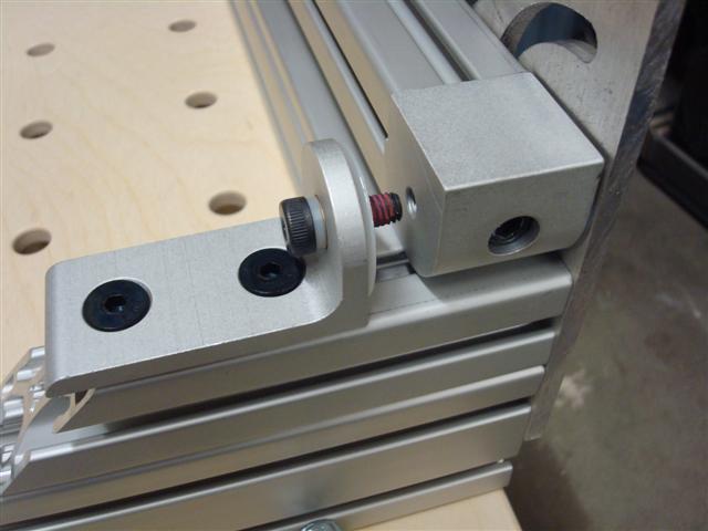
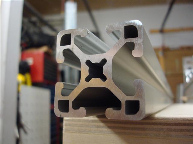
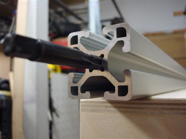
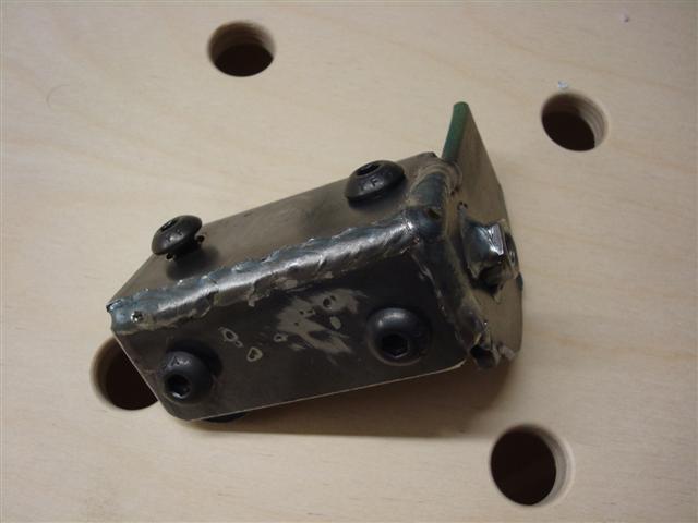
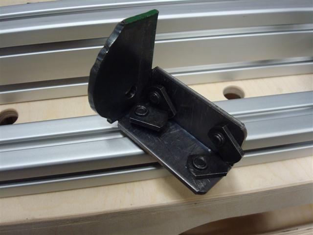
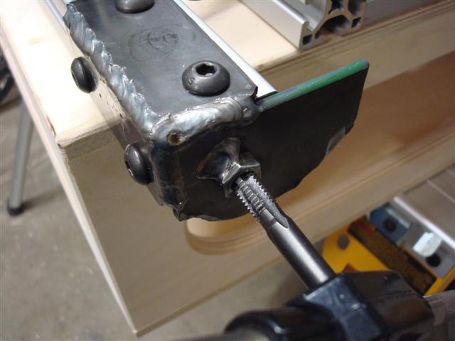
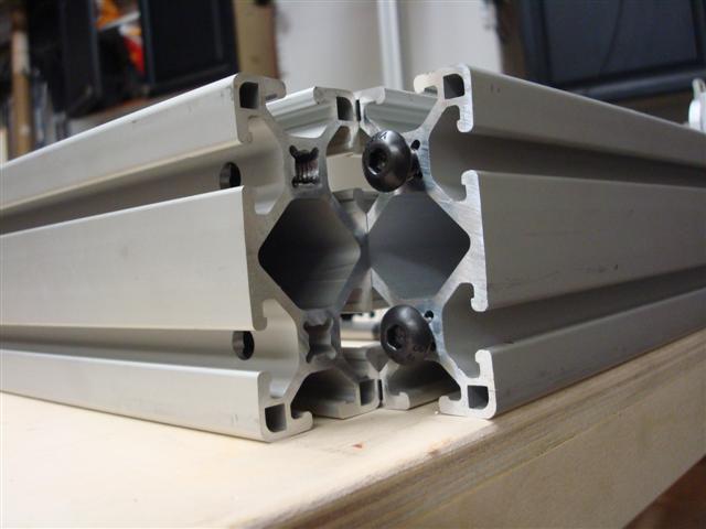
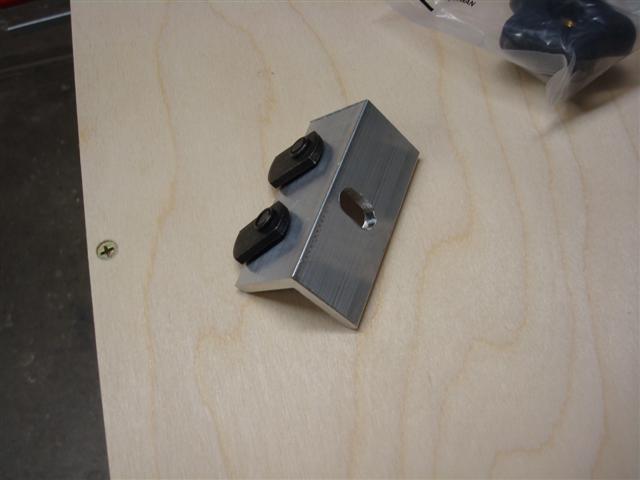
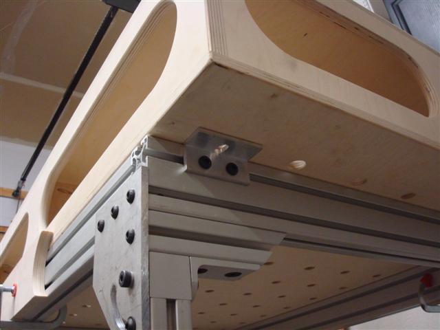
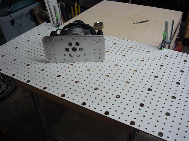
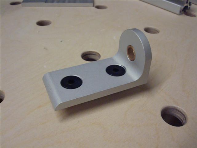
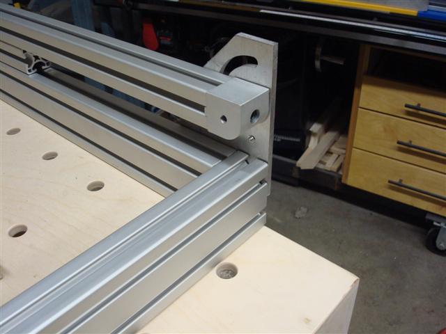
The new pivot block supports arrived this week so now I can finish the inner attachments for the legs. The offset of the bushing center is only 3/4-inch and are specifically designed to work the outer plates on the 15 series extrusions.

MFT28.JPG


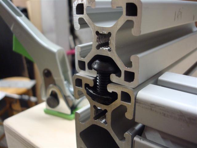
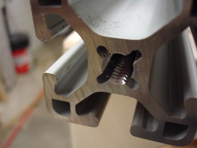
Very little work is necessary to take everything apart and slide the new brackets in. That's a nice feature of the extrusion design.

MFT29.JPG


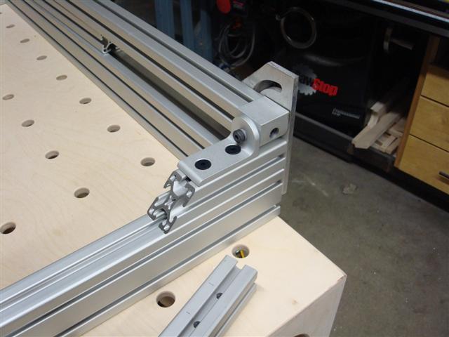
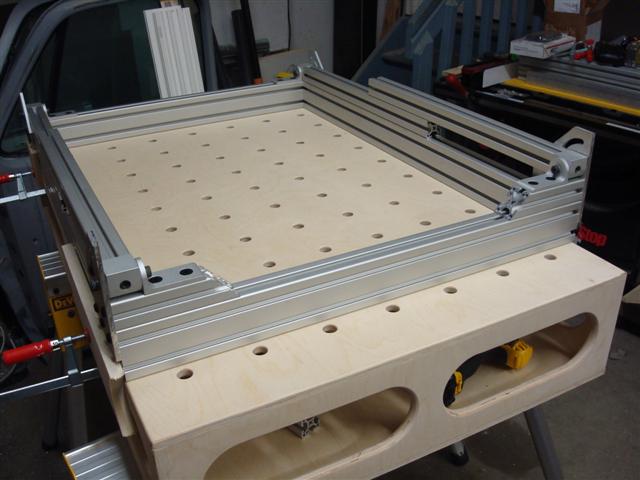
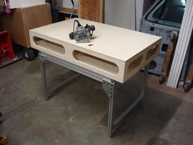
Now two of the four legs are fully attached and ready to support a load. With this end finished, it's time to shift my focus back to the other end again.

MFT30.JPG


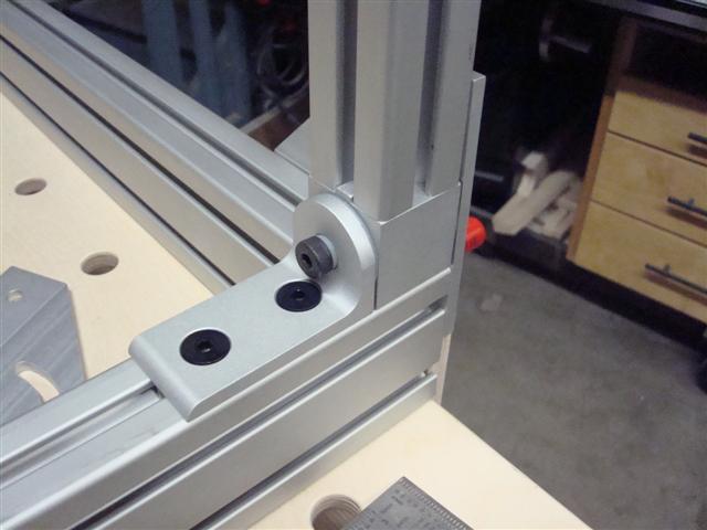
With the new brackets raising the pivot point 1 1/2-inches over the standard brackets I now need to be a little creative to make things work as they should. My new pivot brackets can't make up that distance.

MFT31.JPG


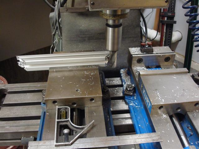
What I need to do is fill that gap. I figure I have few choices - (1) I could switch the end from a 1530 to a 1545 and all would be right instantly. (2) I could cut a small piece of a 1515 to fill the gap. (3) I could make another pivot bracket that's 1 1/2-inches higher to make up the difference and support the pivot.

MFT32.JPG


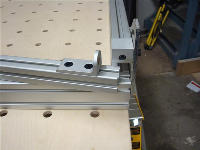
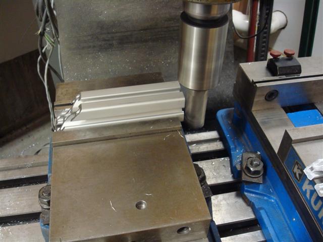
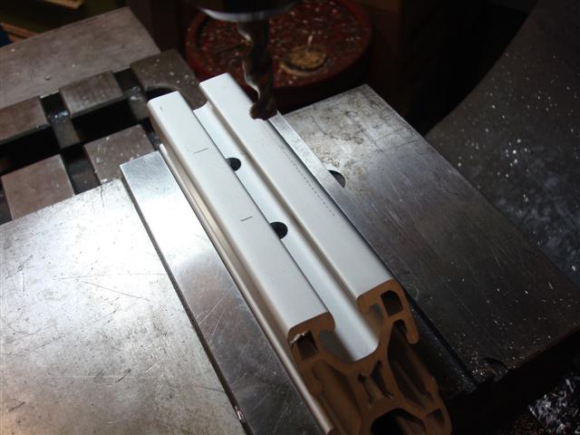
After looking through the material I ordered I found that I really don't have any surplus 1545's and by using even 30-inches of one I'd screw up the plan for the longer table...and I'd end up with a 30-inch long 1530 that would end up just sitting on the shelf. Option (1) is out. Option (3) would likely be the lightest alternative however, after looking, I realized I don't have any material that would make it a simple solution unless I wanted to machine pieces and then weld an assembly. The visual I'm getting his horrid so that's out. So I'll go with (2) - cut a small piece of 1515.
 
To avoid these ads, REGISTER NOW!
OP
L

lilscorpion

Well-known member
Joined
Mar 15, 2010
Messages
3,599
Location
Colorado
I also thought I'd share a new set of clamps that came today with the new pivot brackets. For you Festool guys this won't be a surprise - a pair Festool ratchet clamps.

FTRatchetClamp.JPG


Which look very similar to my Strong Hand ratchet clamps (hmmmm...) just not as heavy duty.

StrongHandClamp.jpg


Right away I put them to work on the MFT (just replaced the screw ones but it made me feel good - ha!).

FTRatchetClamp2.JPG
 

sparksftball69

Well-known member
Joined
Sep 8, 2013
Messages
116
Re: Tool Organization

What started off as a dish drying rack is now my pliers etc holder...bent and painted waiting to dry now...nothing spectacular but thought I'd share...

Sent from my SAMSUNG-SGH-I337 using Tapatalk
 

Attachments

  • uploadfromtaptalk1394948012019.jpg
    uploadfromtaptalk1394948012019.jpg
    77.2 KB · Views: 657
OP
L

lilscorpion

Well-known member
Joined
Mar 15, 2010
Messages
3,599
Location
Colorado
Re: Tool Organization

What started off as a dish drying rack is now my pliers etc holder...bent and painted waiting to dry now...nothing spectacular but thought I'd share...

Sent from my SAMSUNG-SGH-I337 using Tapatalk

I've been holding out on organizing my pliers drawer because I've not found (or come up with) a solution that I really like yet though the dish rack one is probably the best so far. For the smaller pliers is it still easy to get them out? Seems they'd fall down in between and they'd be more difficult to remove when needed.
 

ihrescue

Well-known member
Joined
Dec 30, 2013
Messages
276
Location
Olney, MD
Re: Tool Organization

What started off as a dish drying rack is now my pliers etc holder...bent and painted waiting to dry now...nothing spectacular but thought I'd share...

Sent from my SAMSUNG-SGH-I337 using Tapatalk

Nice idea, it looks like you could do similar with a piece of Closetmaid shelving.
 

sparksftball69

Well-known member
Joined
Sep 8, 2013
Messages
116
Re: Tool Organization

Yes you could...I didn't have a vice so I clamped each section between two pieces of 2x6 against my work bench and used a dead blow gently until I got the bend I wanted.

Sent from my SAMSUNG-SGH-I337 using Tapatalk
 

sparksftball69

Well-known member
Joined
Sep 8, 2013
Messages
116
Re: Tool Organization

I've been holding out on organizing my pliers drawer because I've not found (or come up with) a solution that I really like yet though the dish rack one is probably the best so far. For the smaller pliers is it still easy to get them out? Seems they'd fall down in between and they'd be more difficult to remove when needed.

I don't have any issues with losing the small.ones be you can always bend it to fit your needs...ie make more than one single bend down the middle...I got this one from Walmart and it was just a tall dish rack with legs on each side...$7 for about 32" of storage.

Sent from my SAMSUNG-SGH-I337 using Tapatalk
 

alinc100

Well-known member
Joined
May 26, 2013
Messages
3,010
Location
Dearborn,MI
27 pages and a pot of coffee.This is a great thread, I just found this morning.Read it all and must say the work is fantastic!!!
 

sparksftball69

Well-known member
Joined
Sep 8, 2013
Messages
116
Got an Idea maybe someone else has both...The ernst socket rails are nice...a little pricey but nice. The Harbor Fright (HF) rails are ok but they dont twist lock and the little ball seems to come out of the socket holder and can't be used...I know you can get packs of the ernst socket pegs on amazon for like $4. Does anyone have both and if so...will the ernst pegs fit on the HF rails. Just a thought...most likely not...but i know that the craftsman ones did but they were more expensive and aren't all that great.
 

sparksftball69

Well-known member
Joined
Sep 8, 2013
Messages
116
Re: Tool Organization

Def going to need to repaint...probably use plastidip spray paint...This stuff seems to scuff to easy

Sent from my SAMSUNG-SGH-I337 using Tapatalk
 

Attachments

  • uploadfromtaptalk1395005905659.jpg
    uploadfromtaptalk1395005905659.jpg
    57.2 KB · Views: 327
  • uploadfromtaptalk1395005919290.jpg
    uploadfromtaptalk1395005919290.jpg
    85.7 KB · Views: 444
OP
L

lilscorpion

Well-known member
Joined
Mar 15, 2010
Messages
3,599
Location
Colorado
I got some time to work through the spacer today. I found a left over drop that came from cutting a pair of the legs and it was nearly exactly the same length as the two pieces I needed. The measure said I had about 1/8-inch to play with (after subtracting the width of the saw blade). So that it was easy to hold it in the vise I decided to 45 both ends first and then half it once I was done which allowed me the flexibility to over/under cut one or the other without failing as long as I got the average right.

MFT34.JPG


After cutting them in half on the miter saw I faced both.

MFT35.JPG


The spacer will be attached to the 1530 extrusion and to do so I'll have to embed a pair of T-Nuts and Bolts. I needed to drill some access holes so that I could get the allen wrench in there to tighten them.

MFT36.JPG


Then I tapped the ends so I could attach them to their side plates.

MFT37.JPG


Now the assembly will show you how it all comes together. The T-Nuts (2) go between the spacer (1515) and the cross beam (1530).

MFT38.JPG


Once the two slide together and the allen bolts are lined up with the access holes, they're tightened to keep the spacer in place.

MFT39.JPG


The outer plate is reattached which supports both the (1515) spacer that was tapped in the end and the lower cross beam that was tapped previously.

MFT40.JPG


With the spacer now in place, the live nub can be supported by adding the inner support to the top of the spacer.

MFT41.JPG


And done. In hind sight I wish I'd weighed the spacer, bolts, and nuts so I'd know just how much weight was added by my OCD.

MFT42.JPG


And a finish shot after completing the assembly of both sides.

MFT44.JPG
 

bushmechanic

Well-known member
Joined
Mar 17, 2014
Messages
4,820
Edit: I didn't realize this was 27 pages long. I posted a place to get the HDPE.

I'm sure, however, somewhere in here a few vendors for the material were noted. Oops.
 
Last edited:
OP
L

lilscorpion

Well-known member
Joined
Mar 15, 2010
Messages
3,599
Location
Colorado
Very nice! I've been wanting to use 8020 on a project but just haven't gotten to it. You might like this: 8020 Sysport workbench

Gregor

That's slick. I really like the flexibility of mobile work stations. I know I have very particular tastes but I can't get to the systainer stuff. Are they each purposefully molded or are they generic to fit all kinds of stuff? The ones I looked at when I was in the store seemed to be specifically designed for Festool accessories and/or consumables. They aren't cheap either...some of the shops on FOG have dozens of them if not more. Maybe I just don't get it yet and it'll come to me (though my wife and checkbook won't likely share my ability to be open minded).
 
OP
L

lilscorpion

Well-known member
Joined
Mar 15, 2010
Messages
3,599
Location
Colorado
I took a "mental health day" (the kind the boss is okay with) today which was much needed given the pace of things at work recently. I've gotten far enough that it's time to pull everything apart and tap/drill for the inner bolts. At this point I've tapped maybe a dozen or so times and I'm not extremely impressed with the threads and there's a good reason why the threads I'm cutting aren't turning out so well. Here's the end of the extrusion

MFT50.JPG


I have two, three, and four flute taps in 5/16-18 and the two flute has a burr on it and needs to be resharpened so that leaves me with a three and a four. The three goes in goofy into the profile and does a strange wobble so I've been tapping with the four. The four however, has an entirely different problem. The flutes happen to be the same size as the reliefs and the flutes fall into the reliefs every 90-degrees causing the tap to lose it's place. To illustrate my point, the tap, with flutes lined up with the slot, can be pushed about half way in with no resistance.

MFT51.JPG


In manufacturing fixtures are a way of life. A good fixture can make an operation take less thought which helps reduce error in the results. After tapping half a dozen (and with probably multiple dozens to go) I figured it was time to build a fixture to make the tapping piece a breeze. In my experience, making the fixture takes so little time if you just do it, you may just end up getting it back the first or second time you use it. I weeded through my misc metal tabs and found a few that would work nicely with nothing more than a single cut on the band saw. After cutting the plate in half, I was able to attach the pieces to a sacrificial piece of extrusion. The extrusion, in this case, will keep the pieces exactly where I want them and pull the heat away from the fixture which helps it from distorting. Kind of a nice feature.

MFT45.JPG


This plate, because it will only capture two sides and the face of an extrusion, will allow me to tap just about any piece I need to tap on the end as long as it has two sides 3/4-inches away. All of the 15 series extrusions share this attribute. Here's what it looks like after welding it up. The nut on the end will serve as the guide for the tap and since it's steel and the work piece is aluminum, the tap won't wreck it any time soon.

MFT46.JPG


And a glimpse of the inside of the fixture. Nothing fancy but with the four T-Nuts and bolts, it perfectly aligns. Don't give me flack about not making it pretty and leaving the rough plasma cut edges, it's a fixture.

MFT47.JPG


Once in position and bolts tight, I'm able to tap a hole about as fast as I can spin the tap. Though I haven't done one yet, I may switch to a bottoming tap to regain the depth I lost by adding the nut. It'll take a little more effort to use a bottoming tap but given the reliefs in the extrusion, there's really no reason why I shouldn't.

MFT48.JPG


And the threads look a lot nicer than the threads I'd been making by hand before the fixture.

MFT49.JPG


I think I tapped 50 holes today and am very grateful that I made the tapping jig as I believe it saved me a ton of time. I only had to half disassemble the table in order to finish tighten everything. While reassembling I snapped this shot because it nicely illustrates now the inner bolts work with the thru-holes.

MFT52.JPG
 
To avoid these ads, REGISTER NOW!
OP
L

lilscorpion

Well-known member
Joined
Mar 15, 2010
Messages
3,599
Location
Colorado
All I had left was to build the legs cross braces which involved more thru-drilling and tapping so I didn't take any pictures because I figured I'd already covered that. With the legs complete, I flipped it over. Once the feet are installed it will sit at exactly 36-inches which will line up perfectly with the table saw and other benches around the shop making it a nice add-on when needed. As mentioned previously, I might end up cutting a little off the legs so I can adjust it to be just a hair under 36 to ensure proper alignment when used as an out feet table but I can cross that bridge when I get there.

MFT53.JPG


As of now the torsion box top is just sitting on the frame and easily moves around when bumped. As I've been putting the frame together I've been considering different attachment options I wanted it to be extremely simple. I found some 1 1/4-inch .188 aluminum angle that should be plenty strong and cut two 3-inch long pieces.

MFT54.JPG


I only need one on opposing corners of the table to ensure the table stays put so I decided I'd only make two. The holes in the top have already proven extremely useful for fabrication and it seems they'd also double nicely as attachment points (and prevent me from drilling another set of holes). I milled a 3/8-inch slot in one side of the angle and a pair of 5/16-inch holes on the other.

MFT55.JPG


When attached it will sit flush with the surface of the extrusions and the slot will allow a bolt to go into or through the torsion box (or other tops if I choose to make different ones). To attach them I simply slide them into the upper track and line them up with the outer and end-most holes of the surface of the table (it's upside down in the picture).

MFT56.JPG


Now I need to cut holes in the bottom of the torsion box to match the holes in the top. I could make the bottom just like the top but decided that I'd rather have a surface that doesn't have all of the holes in case I didn't want the holes for some reason (like when doing nuts and bolts stuff). I measured the pattern and copied it to the bottom and lined up my routing jig (same jig I used for the top) on the holes so I could use my router fixture plate - another example how fixtures save me time after the initial investment. It maybe took me a couple of minutes to get holes exactly spaced...awesome.

MFT57.JPG


Pulling the tape indicates that the holes are as close to perfectly square as I can tell (using a tape that is). The pegboard fixture is slick.

MFT58.JPG


To attach through the 3/4-inch hole I need a bushing of some kind. Typically I'd use a plastic but I've been moving around this piece of oak rod that I figured would make nice bushings and chucked it up in the lathe. I'm sure I've mentioned it before but I'm fairly afraid of using a wood lathe which I've been told is odd since I'm such a machine guy. The idea of holding a tool against a rest to me is insane. A metal lathe makes more sense to me. A holder that's attached to a post that's mechanically attached to something weighing 5k lbs...I digress. So I turn them on the metal lathe.

MFT59.JPG


And the pieces - extremely simple and easy to replace if they go missing.

MFT60.JPG


The bushing is snug so it just presses in, slide the bolt through, and screw on the knob.

MFT61.JPG


MFT62.JPG


I'm so close to being finished with it. Now all that's left is the lower shelf (keeps the legs apart when setup and gives me a place to put tools and material when working) and thread in the new feet. The best part is I have two surfaces I can work on. The one with the holes for fixturing -

MFT63.JPG


And the side (mostly) without holes -

MFT64.JPG


The legs don't look like they're straight in the pictures for some reason, I suspect it's the perspective. They're actually perfectly straight and measure exactly the same at the hinge side and between the bottoms.
 

lonestarky

Well-known member
Joined
Mar 28, 2011
Messages
367
Location
Lindenhurst IL
Re: Tool Organization

I was thinking about your tap problem, and though the fixture seems to work great, did you consider a trilobular thread rolling fastener, taptite II for example, and eliminate the tapping altogether? The trilobe has the advantage of never lining up with the 4 slots, though that may also distort the rolled threads. Just a thought.

In regards to fixtures, in addition to the time savings, the quality improvement is noticeable. I'll never forget, you never have time to do it right, but you always have time to do it over..
 

Modern Jess

Well-known member
Joined
Jan 2, 2011
Messages
1,362
Location
Bay Area, California
It took several days to read through the whole thread, but I finally reached the end. Epic! You hooked me with the drawer inserts, lured me in with the cabinetry, and then killed me with the Ron Paulk-inspired table (which I had been meaning to build). I like your interpretation of it, and the pegboard-as-index is brilliant.

I'm going to be stealing some of these ideas. Thanks!
 
OP
L

lilscorpion

Well-known member
Joined
Mar 15, 2010
Messages
3,599
Location
Colorado
Re: Tool Organization

I was thinking about your tap problem, and though the fixture seems to work great, did you consider a trilobular thread rolling fastener, taptite II for example, and eliminate the tapping altogether? The trilobe has the advantage of never lining up with the 4 slots, though that may also distort the rolled threads. Just a thought.

In regards to fixtures, in addition to the time savings, the quality improvement is noticeable. I'll never forget, you never have time to do it right, but you always have time to do it over..

Never heard of thread rolling fastener. Looked them up and I'm going to order some for my next project. I've used thread cutting screws but not bolts. Thanks for the tip.

I very much like that saying. Took me years to figure it out and I still forget from time to time when I'm up against the clock.
 

lonestarky

Well-known member
Joined
Mar 28, 2011
Messages
367
Location
Lindenhurst IL
Re: Tool Organization

They actually work great. They have the advantage, in blind holes, of not producing any chip. In addition, they cold work the material and harden it somewhat, increasing the strength of the joint. They're good for softer material, Al, Zn, but they work in steel as well.
 

jnyost

Well-known member
Joined
Mar 19, 2009
Messages
187
Location
Central Ohio
Re: Tool Organization

I've been holding out on organizing my pliers drawer because I've not found (or come up with) a solution that I really like yet though the dish rack one is probably the best so far. For the smaller pliers is it still easy to get them out? Seems they'd fall down in between and they'd be more difficult to remove when needed.


Love my plier racks. Purchased 1 to try it and liked it so much I bought another one. And I had more than would fit in one.

ImageUploadedByTapatalk1395282814.092641.jpg

http://www.amazon.com/Plyworx-Pliers-Rack-Model-Improvement/dp/B001DZLMFI/ref=sr_1_1?ie=UTF8&qid=1395283423&sr=8-1&keywords=plier+rack
 
Last edited:
OP
L

lilscorpion

Well-known member
Joined
Mar 15, 2010
Messages
3,599
Location
Colorado
Originally the plan for the MFT was to have a router lift installed in one end and then an elimination plate for when I didn't need the router. After using the table for a week I realized that I'd much rather have the router centered in a dedicated table that I can cut custom slots in instead of attempting to make the one I have be everything all at once. Since I'm way to far along with the current top to make a design change so drastic, I'll need to build another top for the router.

Today I started machining the pieces for the router table. Previously I used a hole saw to cut the large reliefs in the side and end plates of the torsion box but this time I thought I'd go all wood worker, make a template, and then use a router to cut out the parts (like I'd seen in Ron Paulk's videos). The plan was to make a template out of MDF (of which I didn't have so I used Melamine) and then trace it with the router. So first I cut out the pattern on the mill to get the exact profile I wanted.

RT1.jpg


Then I tried to trace the pattern with the router a couple of times without much success. I needed to take a couple of passes but since I was using a router bit that had a bearing on it, I needed to take to much of a cut on the first pass to get the bearing to line up so it dug in and ended up wrecking the pattern (like a minute into the first hole). That pretty much pissed me off so I did what all of you expected me to do...

RT2.jpg


I chucked the damn thing up in the mill and used the mill to cut the holes. Saw dust and oiled machines don't mix so I "collected" all of the dust as it was made and I caught almost all of it.

RT3.jpg


I ended up using a 1/2-inch 2 flute end mill but in hind sight I probably should have used a rougher. When climb milling it splintered out a little but when conventional milling it almost didn't splinter at all because the cutter was pushing into the drop instead of into the piece. This is a shot of the finished cut after climb milling. Most of what you see around the cut isn't splintering, it's just fuz.

RT4.jpg


This shot shows the difference between the two tables. Instead of having a brace exactly in the center of the length of the table, there will be two about 14-inches apart with space in the middle for the router. All of the slots were made EXACTLY 12.25-inches long. This is the first time I've ever been able to state exact measurements when woodworking.

RT5.jpg


Here's the parts after rounding over the edges. Now all I need to do is drill the pockets for the pocket screws and I'm ready to assemble.

RT6.jpg


I'm kinda glad I had problems with the router today. Had I not, I probably wouldn't have machined the parts with the mill which ended up a good reminder that I'm far better of doing things my way than I am trying to follow the leader.
 

benjammn

Well-known member
Joined
Apr 27, 2013
Messages
52
Location
Chandler, AZ
sorry to see you had issues with the routing of your templates but glad to see that you mastered the process with the other tools at your disposal
 
OP
L

lilscorpion

Well-known member
Joined
Mar 15, 2010
Messages
3,599
Location
Colorado
Today I assembled the second MFT table that is to serve primarily as a router table (replacing the one I used to have which was attached to my first table saw). With most of the machine work done, today I needed to figure out the hole for the router plate itself and how I was going to integrate dust collection and keep it mobile.

I needed some spacers to lift the sheet up so I started with rounding the edges on all of the cut outs from the side and mid-plates. The're so perfect it seems I might just have keep them around for this purpose.

RT7.jpg


I started by setting the location for the cut out. Fortunately I had the left over jigs from the previous router table so all I really had to do is determine location. I really liked my last setup but failed to take notes so I did a little guessing here.

RT8.jpg


This time I saved my self the headache and pre-cut the hole with the jig saw so that I only had to do a brief once-around with the router to prefect the opening.

RT9.jpg


And to make sure everything was as I remember it, I test fit the router mounting plate (also salvaged from my last table). This is 1/4-inch 6061 I machined and tapped so I could screw it under a table and then use four bolts for easy leveling. It works slick.

RT10.jpg


Since the table surface is only 1/2-inch, I needed to build up the edges so I could screw the plate on. I added 1 1/2-inch wide strips of ply to accomplish this.

RT11.jpg


I used to make a mad mess every time I did glue-ups. After watching some videos on utube I realized that I was doing it all wrong. I used to wiggle some glue on the board and called it good until I saw someone explain how much better glue works if you evenly spread it over the entire surface. I use little strips I cut out of drops to spread it out instead of buying the fancy silicone ones. Once the build-up is complete, I clamp it up and set it aside.

RT12.jpg


While the top is drying I pull out the pocket hole tool and drill the pocket holes for all of the side and mid-plates. Setups on the MFT are so much simpler and make each op feel more organized which ultimately makes the process seem to go faster. Here I use those drops again to support either end of the work piece. Double stacked (net ~1 1/2 inches) is perfect.

RT13.jpg


Here's another example why the MFT is so sweet. I can run a clamp from the inside up and essentially affix the pocket jig to the table to keep it from moving around without the clamp being in the way. That keeps the setup where I left it and it won't budge when I bump into it while moving stuff around.

RT14.jpg


A few minutes later, I'm ready to assemble.

RT16.jpg
 
OP
L

lilscorpion

Well-known member
Joined
Mar 15, 2010
Messages
3,599
Location
Colorado
There's not really a big difference between this one and the first except the two inner pieces. I cut a few spacers out of scrap to get things aligned correctly and then started the glue up.

RT17.jpg


Once assembly is complete I fit the top for alignment and set the router in place.

RT18.jpg


For not intending something to go totally your way...the drops turned on end were the perfect height. When elevating the torsion top with the drops the entire assembly was the exact height as the router + lift + plate at the currently set height. Dumb luck I guess but it's fun to get lucky every so often. Figured I'd throw in a pic to prove it.

RT19.jpg


Next was to figure out how to inset the aluminum track for the miter/sled. As luck would have it, it's 1/2-inch thick and the ply is just shy of that which means I need to cut down into the side after I get things setup the way I want them. Maybe it will be perfect height when I add the laminate. The last top had a 3/4-inch thickness so I was able to just route a groove that was the correct depth and I was done.

RT20.jpg
 
OP
L

lilscorpion

Well-known member
Joined
Mar 15, 2010
Messages
3,599
Location
Colorado
dumb question. What does MFT stand for?

I'm guessing at multi-function table. Am I close?

Yeah. I think that name is used by Festool for their product. I'm calling it that but I'll probably have to change it shortly after I get sued. :rocker:

Had I never heard the term I probably would call the table an assembly table or fixture table. That's what I called my metal tables I used for fabrication back in the day...same thing really just not good for welding.
 
OP
L

lilscorpion

Well-known member
Joined
Mar 15, 2010
Messages
3,599
Location
Colorado
I could have made a guide and used the router to cut the slot but it made way more sense to just cut the top on the table saw. After making the cut and seeing it I decided to add a backer (some meat that the extrusion can attach to). I cut three pieces and the ones on either end had only a 1/32nd difference in length. Not bad.

RT21.jpg


Glue ***** and you can never have enough clamps. Unfortunately I only had enough clamps that could reach to do two boards at a time so once the middle was done I was able to do the two ends. I'd love to buy another dozen clamps but 9 times out of 10 I've been able to make do so on the occasion when I need more, I wait.

RT22.jpg


With the glue dry I flipped the top over and attached the router mounting plate.

RT23.jpg


And flip it over, cut the remaining filler (for the top), drop the router in, adjust the height and get the first visual of how its going to look done.

RT24.jpg


Good progress today. Next step is to flush cut the edges and give it a quick sand. I still need to work out the fence and order the laminate for the surface but I plan to do so tonight so everything can be here ready to go for next weekend.

If I don't count the frame, I'm about a $120 in on this router table. To be fair, I've had a few left over parts from the previous table but even if you count them, I'm doing well. This table is far less expensive than the router table I almost bought at the local woodworking brick and mortar for $500 and it's much bigger, way cooler, and far more flexible. Glad I chose to build it instead of buying the other.
 
Last edited:
OP
L

lilscorpion

Well-known member
Joined
Mar 15, 2010
Messages
3,599
Location
Colorado
I wonder what the OP did this week!

Progress is slow when you're slow to make progress. Unfortunately progress was frozen because I've been hunting for the material I wanted to use for the router fence and have been waiting on a couple of other parts to arrive. Stupid little things can throw me sideways like waiting on a single tap. The feet for the MFT arrived just over a week ago and though I should have been able to tap the feet and install them, I found that the thread length of the feet themselves was far more than the tap I had would be able to go (do to the thickness of the shank). After going through all of my 5/16-inch taps (I have maybe a dozen) I found that none of them had a shank smaller than the threads which, until now, I never even thought about being a problem with my tap collection. Out of dumb luck I managed to score a Gear Wrench tap set that I ran across (thanks to the Hot Deals thread).

MFT66.jpg


When it arrived two days after reaching my tapping dead end I was pleased to find that one of the included taps would work perfectly for the task. Seeing the two next to each other makes the difference obvious.

MFT65.jpg


After using my thread guide tool and the original 5/16-inch tap, this is where the new tap started to engage the material and begin cutting again.

MFT67.jpg


After running the tap as far in as I possibly could (just touching the chuck) I ended up with 1/8-inch more thread depth than necessary for the foot.

MFT68.jpg


And the foot fully seated

MFT69.jpg


Now the table sits perfectly at 36-inches off the ground and lines up perfectly with the table saw. Other than a few subtle tasks, the frame is complete.
 
OP
L

lilscorpion

Well-known member
Joined
Mar 15, 2010
Messages
3,599
Location
Colorado
Just out of curiosity, why not just remove some of the length on the threads of the foot?

That would have been too easy. :lol_hitti

The legs are currently at the length where all of the feet are fully bottomed out so I can only make the table taller. Since I can make it shorter (if I ever need too), I may want that adjustment when that day comes.

As I started tapping more and more of the extrusions I got to thinking that because these are the light extrusions and the threads already don't engage the full amount because of how the extrusion is designed, I figured having as much length of thread as possible would be best for handling weight (if I ever put that kind of weight on the table).

and, being that I fell as though I splurged on these overly expensive fancy feet, it seemed far less destructive to tap a little further than it did to cut a foot and risk an oops.

and since I work alone in my garage for hours on end, I didn't have anyone around me at that critical moment to talk me into just cutting the feet which probably would have worked just fine and taken less than 10 minutes.
 
To avoid these ads, REGISTER NOW!
Top Bottom