To avoid these ads, REGISTER NOW!

Transitier Forklift

OP
Y

Yale

Well-known member
Joined
Oct 22, 2014
Messages
84
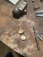
Once I took everything off of the backing plate, I had to decide if I was going to rebuild or replace the brake parts. The first order of business was the wheel cylinder. It looked like it could be rebuilt but I found a new one for $22 so replace it is. However, I still needed to get the short little link rods out of the pistons. The first on freed up with some heat and prying. The second one, however, was explosively ejected to the darkest corner of the shop and could not be located.


BAzFIMtxFpIbRIVsL_wID3-Ww=w1216-h912-no?authuser=0.jpg
1653506706835.png

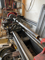
So, off to the lathe to make another one. I found some brass stock that was close enough in size.
1653506784135.png

First, I turned the small end:
1653506823481.png

Then faced the other end and turned the taper:
1653506859363.png

A short trip to the band saw:
1653506909148.png

Some file work and done!
1653506944022.png

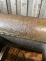
I've got a bunch of parts on order including a new parking brake cable since the casing of the old one was eaten in two by the fan on the generator.
 
To avoid these ads, REGISTER NOW!

Wrench97

Well-known member
Joined
Jun 23, 2018
Messages
12,125
Location
Southeastern Pa
And then you found the ejected link while looking for.................................... :lol:

It's amazing what parts they used on older equipment, I had a old Allis Chalmers F/L with a old Bendix type starter drive from a Ford, a buddy had the old Bendix drive rebuild metal tray assortments I used them several times over the years I had it.
 
OP
Y

Yale

Well-known member
Joined
Oct 22, 2014
Messages
84
And the drum is turned:
1653594363947.png

Since the OD is as-cast, I had to shim it to get it to run true to the sealing surface in the center. I got it within .004" so that should be more than fine for a forklift that won't go over 5 mph.

Something that bothers me about the original design is that the brake line has to make a hard 90 into the back of the wheel cylinder. To fix that, I wanted a 90 degree fitting...which apparently doesn't exist. At least I can't find one. So, back to the lathe.

I started with a 3/8" inverted flare to 1/8" NPT elbow in the 4-jaw:

1653594603758.png

Then, I faced it and drilled it to accept a 3/16" line:
1653594701586.png

Then I silver soldered in a short piece of line with a nut on it:

1653594759105.png

I drilled a little deep but I think it will still seal. If not, I'll do it again.
I also need to make a remote bleed screw as the existing one is impossible to access where it is currently. More on that later.
 
OP
Y

Yale

Well-known member
Joined
Oct 22, 2014
Messages
84
On to the remote bleed screw. from the research that I did, I couldn't find a good OTS solution to this. Apparently, some Jaguars have very inaccessible bleed screws that require special hoses and fittings but those cost more money than I want to spends and would need to be modified. So, custom built it is.

I started with a chunk of brass rod and an inverted flare fitting:
1654795297399.png

Then, I machined them so that they fit together at 90 degrees with holes bored down the centers:

1654795565151.png

Here's a tip for drilling into the side of a piece of round stock, if you have a lathe. First, take a small piece of said stock and bore a center hole on the lathe the same size that you want to drill into the side of the other piece. Then, clamp both pieces in a vise and use the center drilled piece as a drill bushing:

1654795542030.png

I then silver soldered them together and added a piece of 3/16 brake line:

1654795623601.png1654795654558.png

Center drill a bolt and add some copper washers and - banjo fitting:

1654795701432.png

So, that solves one problem. What about the other end?
 

Attachments

  • 1654795403100.png
    1654795403100.png
    1.2 MB · Views: 7
OP
Y

Yale

Well-known member
Joined
Oct 22, 2014
Messages
84
For the bleed screw end, I started with an inverted flare coupler and nut and a bleed screw:
1654795817146.png

Bore out the nut to a #3 and thread to 1/4-28:

1654795862711.png 1654795873555.png

Turn a shoulder onto one end of the coupler, make a bracket and solder it together:

1654795939131.png 1654795971509.png

The tip of the bleed screw seats against the inverted flare fitting quite well so I think this will work great.

Then, mount it in an accessible location:

1654796009073.png

Next, I'll reinstall the brake/transmission assembly and plumb everything back up.
 
OP
Y

Yale

Well-known member
Joined
Oct 22, 2014
Messages
84
I got all of that put back together only to find that my 90 degree fitting had a small leak due to it not seating properly. So, I pulled it back apart and fixed it. The brakes work now but it's leaking gear oil form somewhere so I'll have to fix that. In the meantime, I decided to tackle the front end.

There are 2 problems here:
  1. The cylinder leaks hydraulic fluid out of the gland at the top.
  2. No forks.
I decided to take on the no forks situation first. The big issue is that this machine uses Class I forks which are very difficult to find used. I could buy them new for $500-$800 plus shipping. So, plan B - make regular Class II forks fit. I found a pair on OfferUp for $200 and then went about making them fit. I briefly considered having the hangers cut off and re-welded but that seemed like a pain. So, I decided to modify the carriage instead.

Step 1 - remove carriage. This was a bit of an exercise since I didn't know exactly what the proper procedure was. I eventually figured it out:

1656540901918.png

Step 2 - Clean and mark for incision. Since the carriage is made of a front hanger plate attached to a back 'carrier' plate, my plan was to cut the front plate in half, move it up 3" and weld it back together.

1656541094835.png 1656541113213.png

After a lot of cut-off wheels, cursing, prying and wedging:


1656541182944.png

Clean up:

1656541205667.png

Prying it apart left a bit of a crook in the other half:

1656541246324.png 1656541265900.png

Nothing a little clamp and rosebud action won't cure:


1656541311999.png

Then, 3 passes of 1/8" 7014 all the way around:

1656541372648.png

And, 'new' Class II forks hung:

1656541451115.png

Next up, rebuilding the hydraulic cylinder.
 
OP
Y

Yale

Well-known member
Joined
Oct 22, 2014
Messages
84
Since the carriage was removed, it was a good time to dig into the lift cylinder. It had a nasty habit of spitting and oozing fluid out of the top gland. Seeing as how its a single acting cylinder (fluid on one side only), this meant that, not only was the gland leaking, the main seals were allowing fluid above the piston. First thing to do was block up the mast:

1656623423669.png

Then undo the hydraulic line and the two bolts that hold the bottom in. The top is just a pin into a hole that is supposed to have a snap ring that no longer exists so that came apart easily. Time to strap it down and break out the correct pin spanner...or big a$$ pipe wrench:

1656623577812.png 1656623612507.png

It really didn't take much to unscrew it. No wonder the gland was leaking - there's no wiper!

1656623655671.png

The piston end is just a couple of bronze guide rings and some leather V-packings.

1656623711574.png
 

Attachments

  • 1656623721095.png
    1656623721095.png
    735.1 KB · Views: 16
  • 1656623808981.png
    1656623808981.png
    892.8 KB · Views: 184
  • 1656623848694.png
    1656623848694.png
    1.2 MB · Views: 184
  • 1656623990137.png
    1656623990137.png
    935.7 KB · Views: 190
  • 1656624011464.png
    1656624011464.png
    841.9 KB · Views: 189
OP
Y

Yale

Well-known member
Joined
Oct 22, 2014
Messages
84
Those turned out to be pretty easy to find as well as the proper dust wiper. The rod turned out to be a bit rusty and pitted due to water leaking past the non-existent wiper. So, into the lathe it went:

1656623808981.png 1656623848694.png

I polished from 80 grit up to 1500. I didn't get all of the pits out, of course but it doesn't have to be perfect since it isn't holding hydraulic pressure - just not tearing up the wiper.

From this: To this:
1656624011464.png 1656623990137.png

Then some new packings and slide it all back together. Well, coerce it at least. I added some tape and pipe dope the pipe fittings and re-installed it:

1656624329246.png

Now it goes up and down and all of the fluid stays inside where it should.

Next is to find and fix the gear oil leak, maybe move the propane tank to the back, get the panels beat back into shape and get some paint on it.
 
OP
Y

Yale

Well-known member
Joined
Oct 22, 2014
Messages
84
DETOUR!
Just when I thought this one was about wrapped up, I tried to lift about 500 lbs and the belts for the hydraulic pump started slipping. No problem - just tighten them up.

No more adjustment left...hmmm

Ok, it needs new belts. No problem.

Wait, how do you get them on and off?

1659037329342.png

I guess you take the flywheel off?

1659037370529.png

But the pully and flywheel are one piece?

1659037408663.png

So, how do you get the belts on?

I tried 'walking' them on - which would work for 1 or maybe 2 belts but not for all 3. They just get twisted or walk back off. I even cut some notches in the pump pully to make it work. No luck.
 
OP
Y

Yale

Well-known member
Joined
Oct 22, 2014
Messages
84
I think the way that this is supposed to work is that the flywheel, belts and pump pulley are supposed to slide down onto their respective shafts.

I'm certain whomever engineered this is long since dead but they need to be dug up and killed again.

This design might have might have worked originally....if some jacka$$ HADN"T WELDED THE F'N PULLEY ONTO THE PUMP!

1659037687059.png

So, now I have to open that can of worms. Off with the top cover, motor mount, hydraulic lines and out with the pump.

1659037753053.png

The good news is that the pump internals look good:

1659037836651.png

The bad news is that the pump shaft does not:

1659037919075.png 1659037929274.png

So many botched repairs. So, what I think I'm going to do is clean up the shaft and build it up with weld. Then, I'll have it double keyed and have the pully broached. I also need to replace a bearing in the pump that's smoked. And replace a bunch of other stuff that turned to dust when I took it apart.
 
To avoid these ads, REGISTER NOW!
OP
Y

Yale

Well-known member
Joined
Oct 22, 2014
Messages
84
Quick update - The shaft has been welded up and turned down. It's at the machine shop getting the keyways cut and broached into the pulley. After welding, the shaft turned to butter so I'll need to reharden it. Not knowing exactly what alloy it is, my plan is to heat it to red, quench it in oil and then temper at 4-500 for 20 minutes or so. Then hit it with a file to see where it's at.

Thoughts?
 

bobg03

Well-known member
Joined
Aug 29, 2020
Messages
3,420
Location
conway sc
I worked in a Chemical plant that had once been a Shipyard, even in 1980 we were using machines like towmotors, large scale crawlers on wheels with forks and an antiquated trackmobile..learned to operate some crazy stuff. The 3 wheel forklifts were (as you know) not great with weight and became tipsy.
Great thread happy to have found it..
 

wcp0611

Well-known member
Joined
Nov 25, 2014
Messages
643
Location
Rockvale, TN
Not going to lie, this entire thread turns me on a bit. Great job thus far!

Are you throwing on some pneumatic tires to help with the gravel drive? I have a free-to-me Tusk 5K lift meant for warehouse/concrete floor use and I need to find a way to drive it on my gravel drive as well.
 
OP
Y

Yale

Well-known member
Joined
Oct 22, 2014
Messages
84
Not going to lie, this entire thread turns me on a bit. Great job thus far!

Are you throwing on some pneumatic tires to help with the gravel drive? I have a free-to-me Tusk 5K lift meant for warehouse/concrete floor use and I need to find a way to drive it on my gravel drive as well.
Thanks! I was worried that nobody was interested :).

It already has pneumatics all the way around. I used it briefly on the grass and it didn't get stuck at all. I have it back together now and I'll post an update soon.
 
OP
Y

Yale

Well-known member
Joined
Oct 22, 2014
Messages
84
So, here's the shaft all welded up and looking pretty gnarly:
1664487291810.png

I increased the diameter from 18mm to 3/4" for more strength.

Then I turned it down and had the keyway machined. I also hardened and tempered it back as best I could. We'll see if it lasts. The saving grace is that there is a bearing that the bottom of the pulley rides in that takes the majority of the sideload from the belt tension off of the shaft.

1664487406128.png 1664487432854.png

I also took the time to rebuild the pulley back in to shape a bit:

1664487492630.png

And ground a form tool to re-turn it on the lathe:

1664487531677.png

And re-assembled the pump and valve assembly:

1664487618588.png

And back onto the forklift:

1664487660512.png
 
OP
Y

Yale

Well-known member
Joined
Oct 22, 2014
Messages
84
Another big failure of this design are the tension screws that push the pump away from the flywheel to put tension on the drive belts. The overall design is fine but they used large flat drive screw slots. Over time, they became completely destroyed. So, they need a good cleanup and reengineering. One was in ok shape but the other had lost a good deal of its mass to rust:

1664488202286.png

First step was a good wire brushing and weld build up:

1664488244667.png

Then a spin on the lathe:

1664488280104.png

And then some more welding to fill in the drive slot:

1664488317489.png

And thread cleanup on the lathe:

1664488349992.png

Way better!

1664488375477.png

Back to the lathe to put a pocket on top for a hex drive:

1664488431680.png

More welding and turning and:

1664488456251.png

Reinstalled:

1664488487582.png

They work way better. I don't have to put my entire body weight into keeping the driver in the slot now - they just turn nicely and you can 'feel' the belt tension much better.
 

The Cobbler

Super Moderator
Staff member
Joined
Oct 24, 2013
Messages
25,920
Location
Niagara Region, Ontario, Canada
what a great thread. such a great resurrection of something that was really dead for most people. factoring in your time, probably not worth it, but as a hobby, a great project and will have a great machine at the end.
probably wouldn't pass an inspection but for home use... perfecto!
 
OP
Y

Yale

Well-known member
Joined
Oct 22, 2014
Messages
84
One of the last things to do was clean up the nut that keeps the flywheel on. Coincidently, it looks much the same as the spindle nuts on Dana 44 axles and the socket is a close fit. Like the tension screws, this was mangled by years of the hammer and screwdriver treatment as well:
1664488779658.png 1664488800931.png

More welding:

1664488831816.png 1664488848252.png

And grinding:

1664488884317.png 1664488899063.png

And that now works as it should.

After that, everything was re-assembled. It's now mostly back together and running. However, there is still a brake fluid leak somewhere but I need to move onto other projects so I'll tackle that another time. I'll probably do some cosmetic work and try to get a coat of paint on it this winter if possible.
 
OP
Y

Yale

Well-known member
Joined
Oct 22, 2014
Messages
84
Any updates?
Sorry, I just saw this. As far as the lift, not really. The brake still leaks fluid from somewhere and it still needs paint. Everything else seems to work fine. I've used it to move a few things - the heaviest being my 'new' Buffalo 22" drill press. That experience taught me that having the load off-center from the mass of a 3-wheel forklift is a no-no. Nothing fell or broke but there were a few 'puckering' moments.
I'm currently using it as a fixture to rebuild the rear diff of my '69 Jeep CJ-5 - which is another project that has gone well beyond its original scope.
 
To avoid these ads, REGISTER NOW!
Top Bottom