To avoid these ads, REGISTER NOW!

Troubleshooting hydraulics / lift imbalance issue

jtbinvalrico

Well-known member
Joined
Jan 2, 2010
Messages
1,375
Location
Tampa FL
Hoping you can help me troubleshoot a hydraulic issue on an Atlas FM9SL scissor lift. Here's the full installation thread:

https://www.garagejournal.com/forum/showthread.php?t=383717

The issue: The platforms go up and down evenly when unloaded. But when loaded the slave platform lags about 3/4" behind the master platform.

Some background....I recently replaced a master cylinder that was leaking around the static seal at the upper end cap. GSE sent a new one and I got it in no problem. This leveling issue existed before and after the master cylinder replacement.

Here's the unloaded behavior:

1) Both platforms rise and fall evenly.
2) Unloaded and resting on the locks at any height, both platforms are level to each other.

...and the loaded behavior:

1) Lift the car to mid-height, and the slave side platform is about 3/4" lower than the master side platform.
2) Lower the car to rest on locks, the slave side platform hits the locks first, then the master side platform hits the locks.
3) Lift the car off the locks, and the master side platform lifts that side of the car about 3/4", then the slave side platform picks up and lifts up off its locks.

I called GSE tech support to discuss the issue. The tech said they have no special bleeding instructions not contained in the manual. We did, however, agree that removing, inspecting, and cleaning the check valve (called a Non Return Valve in the manual) would be worth a try. I did this and got no improvement.

As an experiment I lifted a car about a foot off the floor and left it on hydraulics for an hour, the master platform was 5.25" off the floor and the slave platform was 4.5" off the floor. I was wondering if the slave platform would fall over time. It didn't.

Some theories:

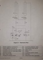
1) Looking at the hydraulic diagram, it appears that if the check valve were failing I'd see the master platform lagging, since the Normally Closed #4 valve would prevent the oil from going anywhere except past a failing check valve. It isn't behaving like that.

2) Is there a bubble somewhere in the slave side - a bubble that has no problem lifting the empty platform, but of course compresses and causes that side to lag under the weight of a car? I don't like this theory because it appears that this system should easily push air through and out to the reservoir.

3) My leading theory: The Normally Closed #4 valve has a minor seal leak. It's letting oil past it on the lift cycle. That escaping oil ends up going through the Normally Open #3 valve (the check valve gives it no other direction to go). The loss of oil that should have gone to the slave cylinder combined with the extra oil the master cylinder is receiving causes the observed behavior.

I've included a hydraulic diagram to look at. Thoughts?
4.jpg
 
Last edited:
To avoid these ads, REGISTER NOW!

matt_i

Well-known member
Joined
Mar 14, 2008
Messages
10,794
Location
SE Michigan
That doesn't even look like it would work lol. That the top port Cyl 1 is hooked to the bottom port of Cyl 2 AND teed into pump pressure at the same time suggests Cyl 1 would be barely able to lift anything (basically limited by the difference between the piston and the piston/rod areas) while Cyl 2 with its top port hooked to tank would be the main lifting device.

It seems like the line from the top port of Cyl 1 should jump over (not tee) the pressure line to the bottom port of Cyl 2 and then tee into the line to tank...but...why tee the top port to tank if its single-acting...

That said are there cables which coordinate motion in this lift?
 

firebirdparts

Well-known member
Joined
Jun 8, 2016
Messages
10,748
Location
Kingsport, TN
If it's consistently 3/4", then it sounds like an air bubble, and the location is pretty obvious. it could even be mechanical, but let's ignore that.

You do have to bleed it, don't you? There is no way for a bubble to get out shown on your diagram.

Your leading theory 3 doesn't make any sense at all. There's no time for that to happen when you lift it off the locks, and there's no reason to think a valve could ever do that consistently. Not to mention the pressure drop is the other way.
 
Last edited:

ZipSnafu

Well-known member
Joined
Mar 8, 2011
Messages
410
Location
Virginia
I too would tend to believe that there is an air bubble in the second cylinder. Just because of the consistency of the drop.
 

vertcnc

Member
Joined
Mar 28, 2015
Messages
18
Once all the hydraulic components are filled with oil (cylinders, lines..etc) the side with the least resistance will move before other. You would need some type of flow control to make them move exactly the same. So if one side the vehicle is lighter or one cylinder has looser tolerances then the other, it will move first. It's actually a very complicated problem to solve.
 
OP
J

jtbinvalrico

Well-known member
Joined
Jan 2, 2010
Messages
1,375
Location
Tampa FL
That doesn't even look like it would work lol. That the top port Cyl 1 is hooked to the bottom port of Cyl 2 AND teed into pump pressure at the same time suggests Cyl 1 would be barely able to lift anything (basically limited by the difference between the piston and the piston/rod areas) while Cyl 2 with its top port hooked to tank would be the main lifting device.

It seems like the line from the top port of Cyl 1 should jump over (not tee) the pressure line to the bottom port of Cyl 2 and then tee into the line to tank...but...why tee the top port to tank if its single-acting...

That said are there cables which coordinate motion in this lift?

The top port of 1 is T'd into the bottom port of 2, but below that is a leveling valve that is normally closed, which causes oil exiting the top of 1 to enter the bottom of 2, effectively turning that T into an elbow. By opening the valve under 2 and closing the valve under 1, you can adjust any imbalance.....at least in theory. But why would we need leveling valves if it's self-leveling....? :confused:

Why not send the top of 1 directly back to the tank? It appears as if they've tried to make it self-leveling and self-bleeding. I get the concept. Use the top end of 1 to act as a pump to drive the bottom side of 2. In fact, cylinder 1 is quite a bit bigger than cylinder 2....I did the math, too. The volume of the rod side of cylinder 1 equals the volume of the head side of cylinder 2.

It's supposed to be a continuous loop. Cylinder 1 fills first, lifts all the way up, tops out, as oil continues to be pushed in it bypasses the head and is now sent under pressure to the bottom of cylinder 2. Cylinder 2 rises all the way up, tops out, and that excess oil is returned to the reservoir.

After replacing the master cylinder, I disassembled the old one to see how it works and maybe find the cause of the leak. There's a 1/4" hole at the very top of the cylinder end cap. That hole goes through the threaded-on end cap and terminates at the port fitting. But how does oil get from the head side of the cylinder to the rod side? It looks as if there's a tapering down, a bit of a shoulder along the cylinder wall that drops off right about where the ram would top out. I think that's the point at which oil bypasses over to the ram side and continues along this process.....So it seems to my novice eye.

There are no mechanical cables. It's two platforms flush-mounted into the floor, connected only by this shared hydraulic system. The motion is supposed to be coordinated by the nature of the hydraulic layout. If you erase valve number 4 and the lines leading to and from it, you see this is simply a continuous loop intended to be self-leveling (based on the math behind the differing cylinder sizes) and easy to bleed (because air should be ideally shoved out of the top of 1 and into the bottom of 2, then bypassed by the head of 2 and pushed on back to the reservoir.

That's all just me speculating and trying to learn. Take everything I've said with many grains of salt. :beer:

If it's consistently 3/4", then it sounds like an air bubble, and the location is pretty obvious. it could even be mechanical, but let's ignore that.

You do have to bleed it, don't you? There is no way for a bubble to get out shown on your diagram.

Your leading theory 3 doesn't make any sense at all. There's no time for that to happen when you lift it off the locks, and there's no reason to think a valve could ever do that consistently. Not to mention the pressure drop is the other way.

I've bled it many times. At first glance, I would've thought that air bubbles would be pushed through the system in this continuous circuit....Shows what I know.

As far as mechanical causes, I can say that everything is level, runs smooth, no rattling, no flex or unexpected movement in the scissor arms and connections.

Theory 3.....:spit:. Any ideas on bleeding? I've read that air ultimately works it's way out of the system. Maybe I'm making a big deal out of nothing.
My guess would be air between the rod end of the master and cap end of the slave.

Consensus so far. I guess the biggest tell here is the fact that the slave cylinder lags only when the lift is loaded. It doesn't do it at all empty; it does it a bit with a riding mower straddling both platforms; and it does it the most with a car loaded.....Sounds like an air bubble getting squeezed by more weight and exhibiting this behavior.
 
To avoid these ads, REGISTER NOW!
OP
J

jtbinvalrico

Well-known member
Joined
Jan 2, 2010
Messages
1,375
Location
Tampa FL
Expanding on the probability of air being trapped in the head side of the slave cylinder....I've added some pictures for perspective, and also because threads without pictures ****.

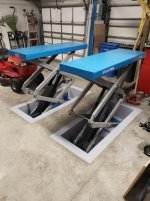
Here's the lift, master cylinder in the left one, slave in the right:
1.jpg

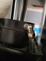
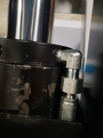
At the top of the slave cylinder is a clear return hose that is apparently a straight shot back to the reservoir. What I noticed about this fitting is that it swivels. It's snugly screwed into the port, but the body of the fitting wobbles around. It doesn't leak though:
2.jpg

Contrast that with the hard fitting on the master cylinder. I understand that the swivel fitting and the clear hose aren't under pressure, whereas this one is under pressure and in fact drives the slave cylinder:
3.jpg

I did an experiment. My theory this time was that even though the swivel fitting is essentially "no pressure", that it should at least stiffen up a bit while lifting. So I tied a length of string to it. Resting on the locks, I can tug on the string and the fitting swivels around. Pressing the up button, the first couple of seconds a tug on the string moves the swivel. As it continues to rise, tugging on the string meets resistance and the fitting stops swiveling.

This suggests to me that this swivel fitting achieves some sort of seal under some amount of pressure. Is it possible that when it's not under pressure, air could leak past the swivel part and into the top of the cylinder?.....and then when the slave cylinder was lifted to max height some air could be drawn over into the head side of the slave cylinder?

If the slave cylinder was never "topped out", this air would never be an issue. But when I follow the instructions to max out and lift both platforms all the way up, that bit of air crossed the gap/space/whatever it is, and resides there, causing this annoyance.

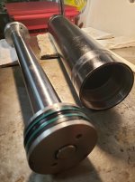
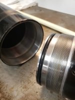
More pictures from the cylinder autopsy are below, suggesting how oil could "bypass" the head. Note the hole in the bottom of the end cap in the far end of the photo (I've got it turned around for the sake of the photo...) Note that when the end cap is threaded on, there's a dip in the wall of the cylinder....to let oil past when the ram is topped out? I don't see how else oil could get past it, which seems to be one of the principles this whole thing was designed on. I'm guessing here. I don't yet understand how and at what point oil gets past the head to make this thing work. Something special about those seals?

If the slave cylinder is constructed the same way, wouldn't the area where the head tops out and oil is bypassed be an ideal area for air to come back across, maybe let in by that swivel fitting? So simply decide to never top out the cylinder - but it's already been done. Maybe topping out the cylinder isn't the problem. Maybe a leaky swivel fitting is. It could **** air in when swiveling, but tightens up under any positive pressure, as seen in the experiment. The clear line has no air in it; it's all oil.

I'm thinking of the times I've bled brakes, and why you want to tighten that bleed screw down while fluid is coming out to eliminate air and create a solid line of brake fluid back to the master....Why did they use a swivel fitting here? There's no reason to. It's sibling on the other cylinder is a hard fitting. I'll bet that this swivel fitting is the most easily obtained fitting that will accept the clear hose and compression nut.

What if I replaced that swivel fitting with a hard fitting and ran a regular hydraulic hose from there to the reservoir fitting in the control box? I've got an extra hose because I had longer ones made up. I guess I lose the ability to monitor the return line in that clear hose. But I think the selection of the swivel fitting and the clear hose had more to do with cost, a bit to do with the low-to-no pressure nature of that side of things, but with no consideration for the possibility that air could get past it.

I've not seen this issue reported with other users of this lift, so I could start by replacing just the swivel fitting. Easy and cheap idea.

4.jpg
5.jpg
 
OP
J

jtbinvalrico

Well-known member
Joined
Jan 2, 2010
Messages
1,375
Location
Tampa FL
Try leaving both leveling valves open then run it to full extension and retraction a few times.

I'll do this later today. Also, I'm leaving town for a few days. I'll leave the platforms extended open while I'm gone....That would get the cylinders as close to standing on their ends as possible, about 15 degrees off vertical. Maybe that will encourage an air bubble to leave.

I think I need to step back and let some of this work out for a while. Another user of this lift chimed in on my installation thread and said his similar issue worked itself out.

Thanks all.
 

Monza Harry

Well-known member
Joined
Dec 29, 2018
Messages
1,433
Location
Windsor ON
JTB, If I'm reading your post correctly the fluid comes out of the master [top] to the slave at the bottom as you have only one pressure line from your pump [no "Tee"] The air diagnosis seems correct to me just where you think it is isn't correct. The air is between the master and slave [not o the top of the slave]. The seals in the cylinder will not stop the air from escaping to the low pressure side of the cylinder, but it may take a couple [lots] of cycles for it to all work its way out. If you can hold the pressure on the cylinder this will help [you may have to bypass a safety or two, and a full squeeze shouldn't be required, 1/3 should allow enough oil to get past the internal seals of the master and then through the slave and then press the air past the internal seals of the slave cylinder. with everything being new, not much oil will get by, the air will be gone from the master immediately, but now you need oil to press the air out, patients will take care of this. Harry
 
OP
J

jtbinvalrico

Well-known member
Joined
Jan 2, 2010
Messages
1,375
Location
Tampa FL
Will do. Sounds like a combination of leaving it up off the locks (unloaded, of course) and repeated cycling will remedy this.

Sent from my SM-G960U using Tapatalk
 

Fix Until Broke

Well-known member
Joined
Feb 21, 2016
Messages
796
Location
SE Wisconsin
From reading the above, I'm reasonably confident that there is an air bubble between the rod side of Cylinder 1 (master) and the head side of Cylinder 2 (slave). Cylinder 1 is the pump for Cylinder 2 - the equal areas of the rod side of 1 and the head side of 2 are what make the two cylinders lift symmetrically. This assumes that there is no "squishy" between the two. An air bubble compresses without the 2nd cylinder moving.

Let's rule out a few misconceptions...

1) There is no "bypass" across the cylinder pistons.
2) The rod side of Cylinder 2 and it's fitting has nothing to do with this. It is connected to tank because that's the easiest/cheapest way to keep dirt/dust/**** out of the cylinder which will eventually damage the seals.
3) Any air bubble between cylinders 1 and 2 will NOT work its way out. That oil is trapped and never goes back to tank or exchanges with any other oil where it can have a chance to release it's air in the reservoir.

One of the challenges of getting air out of this particular system is the relatively low velocities/flow rates. Slow moving oil won't carry air "down" so we need a different approach to get the air out.

I have not read the factory bleeding procedure.... but here's how I'd go about it and the reasoning behind it.

- Load up the slave platform only with as much weight as you can possibly get - more is better

- With the system having been off for quite a while - shine a light in the reservoir and insure the oil is clean/clear - no air, no champagne bubbles, nothing but clean clear (amber?) oil. If you can sacrifice a cheap flashlight on a string, it's easiest to drop it to the bottom of the reservoir with the light on. This will give you a much better visual of any bubbles in the oil than having to deal with the reflection off the top surface.

- With valve 3 open and valve 4 closed - extend both cylinders until they stop and deadhead sending the pump over relief (valve 7). You can hold the cylinder deadheaded for a few seconds.

- Close valve 3 and open valve 4

- Open valve 8 which should lower Cylinder 2 only. Lower it as quickly as you can

- Shine a light in the reservoir again looking for air bubbles - you should see some, likely a "smokey" trail or upside down mushroom cloud from the return of valve 12

- Wait until all bubbles have risen to the top - likely at least 15 minutes, maybe an hour.

- Close valve 8 and turn on the pump which should raise Cylinder 2 only - raise until deadhead

- Open Valve 8 and lower Cylinder 2 only

- Repeat raising Cylinder 2 --> deadheading --> lowering --> Checking reservoir for air bubbles until you get no air bubbles back in the reservoir.

The theory behind this is that air will dissolve into oil when pressurized, just like CO2 will dissolve in soda and will come out in a similar way when the pressure is reduced. By deadheading the cylinder, this sends the pressure to the maximum in the system which will dissolve the most amount of air into the oil. If we didn't put an external load on cylinder 2, as soon as we opened valve 8 to lower the cylinder, the pressure would drop to near zero and all the air would come back out of the oil pretty much right away and still be trapped in the cylinder.

By loading cylinder 2 with as much weight as possible, the high pressure is maintained (and the air stays dissolved) in the cylinder and plumbing all the way back to valve 12 where it finally can drop to atmospheric pressure therefore releasing the air in the tank.

By isolating cylinder 2 with cylinder 1 extended, closing valve 3 and opening valve 4, this allows for the most oil to get exchanged within cylinder 2 to get back to tank and release the air that has been dissolved into it.

We have to wait for the air bubbles to float to the top of the oil in the reservoir after each cycle so that the pump does not pull these air bubbles back in and re-contaminate the system with the same air we just took out.

Sorry if this got long winded - it sounds much more complicated than it really is. Hopefully the process and reasoning make sense.

Good luck - let us know how it goes!
 
OP
J

jtbinvalrico

Well-known member
Joined
Jan 2, 2010
Messages
1,375
Location
Tampa FL
I have not read the factory bleeding procedure.... but here's how I'd go about it and the reasoning behind it.

Wow....Thanks for the write up!

I need to pull the slave platform to take a little height out of the far end of the pit....The pits are near dead level, but when the math is all done the far end of the slave platform itself is a shade taller than the front of the slave platform and the entire master platform. Instead of shimming the entire master platform and the front of the slave platform up 3/16", I prefer the idea of simply lowering that end 3/16" and calling it done.

After that, I'll reassemble, use the above-described bleeding method, and report back with results.
 
To avoid these ads, REGISTER NOW!
Top Bottom