28′ x 28′ garage under construction by a many decades experienced garage builder, and am curious if the construction methods are up to code, or even a good idea.
Specs:
Size: 28′ x 28′
2′ x 6′ walls
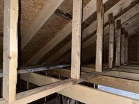
2′ x 10′ rafters
Pitch 7/12
Slab on grade
Zip sheathing walls and roof
One large bay with 18′ x 7′ garage door (no columns or supports).
Photos attached
Questions:
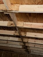
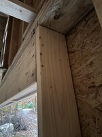
Can one really use scrap pieces of Zip sheathing as ‘mending plates’ I’ve only seen metal plates used.
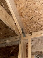
How about ‘sistering’ those two 14′ boards on the ceiling joist using, again, scrap sheathing? There is no center support pole or post.
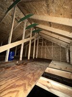
Is one king post in center, and then shorter posts on either side (do not know the term) enough to support weight for storage above the plywood ceiling?
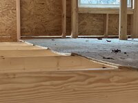
Builder said we could store lightweight items on that plywood floor, add more plywood sheets to make more storage area, and if we wanted to store more weight, he could add two LVLs, but support on garage door end would only be on garage door header, whereas on opposite wall he could install vertical support beams.
Thanks
Specs:
Size: 28′ x 28′
2′ x 6′ walls
2′ x 10′ rafters
Pitch 7/12
Slab on grade
Zip sheathing walls and roof
One large bay with 18′ x 7′ garage door (no columns or supports).
Photos attached
Questions:
Can one really use scrap pieces of Zip sheathing as ‘mending plates’ I’ve only seen metal plates used.
How about ‘sistering’ those two 14′ boards on the ceiling joist using, again, scrap sheathing? There is no center support pole or post.
Is one king post in center, and then shorter posts on either side (do not know the term) enough to support weight for storage above the plywood ceiling?
Builder said we could store lightweight items on that plywood floor, add more plywood sheets to make more storage area, and if we wanted to store more weight, he could add two LVLs, but support on garage door end would only be on garage door header, whereas on opposite wall he could install vertical support beams.
Thanks