To avoid these ads, REGISTER NOW!

Trying to get the air compressor hooked up...

4rcFed

Well-known member
Joined
Jan 22, 2011
Messages
108
Location
Pittsburgh, PA
We moved to our new place this summer and I am finally getting around to hooking up the compressor. I ran the conduit and wired it in last night, but it keeps tripping the breaker at this point. So that is under investigation.

But I forgot to hook up the terminals for the pressure switch.

Pic 1 - the compressor
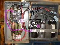
Pic 2 - the white and black wires for the pressure switch
Pic 3 - the panel on the compressor

Does anyone have a compressor like this, or know where I can find out where the white and black wires from the pressure switch attach to the magnetic starter? (Forgot to label them when we moved:lol_hitti)

DSC_0552.jpg


DSC_0553.jpg


DSC_0554.jpg
 
To avoid these ads, REGISTER NOW!
OP
4

4rcFed

Well-known member
Joined
Jan 22, 2011
Messages
108
Location
Pittsburgh, PA
Awesome! Thank you. I went out to the shop and stared at awhile and then came back to check here and saw your post. I think that I actually had it going to how the diagram said to.

Now I have to figure out why I am getting sparking from under the breaker. Need ot determine if something is mis-wired or a bad breaker.
 
OP
4

4rcFed

Well-known member
Joined
Jan 22, 2011
Messages
108
Location
Pittsburgh, PA
Changed out the breaker last night and the compressor fired right up.:beer:


Now I need to layout how I want the piping for the shop to be.:headscrat
 
OP
4

4rcFed

Well-known member
Joined
Jan 22, 2011
Messages
108
Location
Pittsburgh, PA
Thanks.:thumbup:

I actually never measure this shop yet. It is a detached garage with two 16' garage doors. I would guesstimate the length to be 40' and the depth between 25' and 30'. I don't quite think it is a 30'x40', but I guess I should measure it!:bounce:
 
OP
4

4rcFed

Well-known member
Joined
Jan 22, 2011
Messages
108
Location
Pittsburgh, PA
That's what I'm doing on here tonight - researching!

I can't seem to find picture of the garage right now, but looking at the front of it, there is a man door on the left, then a garage door, a space, another garage door, and then the wall.

The compressor is basically in the left front corner, near the man door. I was initially thinking of a couple drops with quick connects near the garage doors, and maybe two hos reels up front? That is probably more than enough drops???

The main thing right now that I am trying to figure, since I want to try to do this right this time, is where I should mount my filter.
 

930dreamer

Super Moderator
Staff member
Joined
Oct 7, 2009
Messages
22,948
Location
Amarillo,TX and Stinnett,TX
That's what I'm doing on here tonight - researching!

I can't seem to find picture of the garage right now, but looking at the front of it, there is a man door on the left, then a garage door, a space, another garage door, and then the wall.

The compressor is basically in the left front corner, near the man door. I was initially thinking of a couple drops with quick connects near the garage doors, and maybe two hos reels up front? That is probably more than enough drops???

The main thing right now that I am trying to figure, since I want to try to do this right this time, is where I should mount my filter.

No expert here, what I did is I ran as much black pipe (FREE) away from the compressor along and down the long wall. Then installed all the filter/regulators etc before the final drops. I moved all my pics onto a back up hard drive so no pics.
Search installing air line/ airlines for some ideas.
 
OP
4

4rcFed

Well-known member
Joined
Jan 22, 2011
Messages
108
Location
Pittsburgh, PA
Question??!!!


(the compressor has been hooked up for awhile and running beautifully...) Today, I went out to work on a tractor, so I went to fire up the compressor, as I shut it off at the breaker in the fuse panel.

I flip the breaker, and just a very load buzz/humm goes on, but the compressor does not run. I had my wife throw the breaker on, and I can see the square button in the middle of the motor starter go in, but just a buzz.

****!!!

Any ideas on what is wrong?:shocking:

I can spin the pulleys on the compressor and motor by hand.
 

larry_g

Well-known member
Joined
Apr 28, 2007
Messages
16,874
Location
oregon
A guess would be the start Cap is shot. Look at the caps to see if one has a bludge in the end or a blown out look to it. Also check that you have 240 volts at the compressor, you may have a bad breaker if you are using it as a switch.

lg
no neat sig line
 

wyliesdiesels

Well-known member
Joined
Aug 14, 2012
Messages
19,995
Location
Modesto, CA
It could be a number of things. Since it sounds like the coil in the starter is working, its safe to say that the overload isnt causing the problem. Im wondering if one of your caps is bad. Check the voltage at your compressor motor terminals while turning the power on to the starter.
 
OP
4

4rcFed

Well-known member
Joined
Jan 22, 2011
Messages
108
Location
Pittsburgh, PA
The breaker is new(er). I put a new one in when I hooked all of this up.

Any idea on how to figure out which cap is the starter cap? Never fooled with replacing one of these. Does just about anyone sell them, or are they a specialty deal?
 

pattenp

Well-known member
Joined
Jun 4, 2008
Messages
10,175
Location
Virginia - USA
The plastic one is the start cap. You you have a decent multimeter it should have a cap test feature. The symbol on the tester looks something like this. --| |--.
 

Charles (in GA)

Well-known member
Joined
Jan 11, 2006
Messages
12,489
Location
50 mi south of Atlanta
Something I noticed that doesn't look right. The pressure switch is mounted on a pipe with the gauge, and has a shut off valve on it. I HOPE that the pressure switch is plumbed directly to the tank and that the shutoff valve is on the outgoing side..... You never want any kind of valve between the tank and the pressure switch.

Charles
 

larry_g

Well-known member
Joined
Apr 28, 2007
Messages
16,874
Location
oregon
The breaker is new(er). I put a new one in when I hooked all of this up.

That was a year and a half ago and if you have been using it as a switch then it could be suspect. Not the best idea to use a breaker as a on/off switch. If you look at your schematic it shows a Auto/off/Hand switch and that is what you should be using.

lg
no neat sig line
 
To avoid these ads, REGISTER NOW!
OP
4

4rcFed

Well-known member
Joined
Jan 22, 2011
Messages
108
Location
Pittsburgh, PA
Something I noticed that doesn't look right. The pressure switch is mounted on a pipe with the gauge, and has a shut off valve on it. I HOPE that the pressure switch is plumbed directly to the tank and that the shutoff valve is on the outgoing side..... You never want any kind of valve between the tank and the pressure switch.

Charles

The valve IS on the outgoing side, and that was an old set-up from another shop. I need to snap a pic of the current piping.

As far as checking the start cap.....what is the process of pulling it and checking...mainly concerned about checking it properly first to ensure that it is drained of current.
 

wyliesdiesels

Well-known member
Joined
Aug 14, 2012
Messages
19,995
Location
Modesto, CA
The breaker is new(er). I put a new one in when I hooked all of this up.

Any idea on how to figure out which cap is the starter cap? Never fooled with replacing one of these. Does just about anyone sell them, or are they a specialty deal?

In a motor control circuit, the feeding breaker does NOT provide overcurrent protection because of the high starting current nature of motors(6x-8x FLC!). The feeding breaker(or fuses) only provide short circuit and ground fault protection.

The device(s) that provide(s) overcurrent protection is called (an) overload(s). This protects the wire and motor from excessive current(and thus excessive heat) and are usually attached to the bottom of starters, depending on the brand but can also be a separate device located below the starter. In your case, the overload is separate from the starter and is connected to the output of the starter and has 3 red wires connected to it.

But if your overload was tripped, the starter coil wouldn't even work. So thats why I said to check the voltage at the motor terminals AND test the start cap!
 

KenC

Well-known member
Joined
Dec 20, 2009
Messages
2,578
If you turn the motor off using the breaker, the pressure on the compressor to tank is not bled off, 'cause the unloader valve wasn't tripped. It is normally tripped by the pressure switch when it turns the power off to the motor. So, if you now turn the breaker on, and the pressure switch is calling for the motor to run, it is trying to start against the residual load. May not be your problem, but worth looking into.
 

foolishpride

Well-known member
Joined
Mar 21, 2009
Messages
343
Location
Southwestern Ohio
In a motor control circuit, the feeding breaker does NOT provide overcurrent protection because of the high starting current nature of motors(6x-8x FLC!). The feeding breaker(or fuses) only provide short circuit and ground fault protection.

Wylie, short circuit conditions and ground faults are considered overcurrent conditions, and the breaker would trip on instantaneous, but these small molded case breakers typically trip on instantaneous at around 10X the breaker rating.

The device(s) that provide(s) overcurrent protection is called (an) overload(s). This protects the wire and motor from excessive current(and thus excessive heat) and are usually attached to the bottom of starters, depending on the brand but can also be a separate device located below the starter. In your case, the overload is separate from the starter and is connected to the output of the starter and has 3 red wires connected to it.

The overloads are sized according to the motor horsepower, and is the motors primary protection. The breaker is sized to protect the wire.

But if your overload was tripped, the starter coil wouldn't even work. So thats why I said to check the voltage at the motor terminals AND test the start cap!
 

pattenp

Well-known member
Joined
Jun 4, 2008
Messages
10,175
Location
Virginia - USA
Here's a couple Youtube videos on how to test caps.


The valve IS on the outgoing side, and that was an old set-up from another shop. I need to snap a pic of the current piping.

As far as checking the start cap.....what is the process of pulling it and checking...mainly concerned about checking it properly first to ensure that it is drained of current.
 
OP
4

4rcFed

Well-known member
Joined
Jan 22, 2011
Messages
108
Location
Pittsburgh, PA
Drain all air pressure, then try to start it. If it takes off, then the problem lies with the unloaded. Report back.

Currently there is no air in the system.

But I thought the other day that I noticed 'more than usual' some air coming out of the pressure switch housing. Not sure if that is a sign of the check valve or not. But I didn't think either of these would cause a no-start condition, with an empty tank.
 

koditten

Well-known member
Joined
Apr 10, 2008
Messages
5,528
Location
Midland, Michigan
Have you tried to roll the compressor pulley by hand? There should be a air amount of resistance, but you should be able to turn over the compressor. Hopefully nothing internally in the compressor is binding up.
 

wyliesdiesels

Well-known member
Joined
Aug 14, 2012
Messages
19,995
Location
Modesto, CA
Wylie, short circuit conditions and ground faults are considered overcurrent conditions, and the breaker would trip on instantaneous, but these small molded case breakers typically trip on instantaneous at around 10X the breaker rating.


The overloads are sized according to the motor horsepower, and is the motors primary protection. The breaker is sized to protect the wire.

Hmmm. Not the way I learned it nor the way others see it. If u have a code book see NEC 430.31.

Quote taken from comment #5 in a thread on mike holt's site:

http://forums.mikeholt.com/showthread.php?t=122274

Motor overload protection devices like heaters protect the motor, the motor control equipment, and the branch-circuit conductors from motor overload and the resultant excessive heating (430.31). They don't provide protection against short-circuits or ground-fault currents. That's the job of the branch and feeder breakers, which don't provide motor overload protection. This arrangement makes motor calculations different from those used for other types of loads. Let's look at how to apply Art. 430, starting at the motor.
 

foolishpride

Well-known member
Joined
Mar 21, 2009
Messages
343
Location
Southwestern Ohio
Hmmm. Not the way I learned it nor the way others see it. If u have a code book see NEC 430.31.

Quote taken from comment #5 in a thread on mike holt's site:

http://forums.mikeholt.com/showthread.php?t=122274

Wylie, do you know what the definition is of an Instantaneous Overcurrent Condition is? It is the condition that exists when there is a Phase to Ground, or a Phase to Phase fault. They are still considered Overcurrent conditions.

Look at how an ABB CO Overcurrent relay operates, or a G.E. IAC Overcurrent relay operates. They sense Overcurrent or Instantaneous Overcurrent conditions, and operate the breaker to clear the condition.
 
OP
4

4rcFed

Well-known member
Joined
Jan 22, 2011
Messages
108
Location
Pittsburgh, PA
Well....did so much running around today, I haven't had a chance to check anything.:(

But while running around, I stopped at the original place that this compressor came from, way back in the day - old school hardware shop. And most of the old school guys still work there!!:thumbup:

I described the condition and had a couple pictures of the set-up and he said "replace the pressure switch".

Would that cause a no-start condition like that, if it were bad?

Also, I was wondering if there was an updated switch as mine does not have a on/off lever on it, hence why I was using the breaker.

My current switch is:

Furnas 69MB8
 

mtnkrake

Well-known member
Joined
Jan 24, 2007
Messages
467
You should be able to wire a toggle switch inline with the pressure switch to control the contactor. That is how mine is wired.
 
OP
4

4rcFed

Well-known member
Joined
Jan 22, 2011
Messages
108
Location
Pittsburgh, PA
But while running around, I stopped at the original place that this compressor came from, way back in the day - old school hardware shop. And most of the old school guys still work there!!:thumbup:

I described the condition and had a couple pictures of the set-up and he said "replace the pressure switch".

Would that cause a no-start condition like that, if it were bad?

Just trying to understand if you think the pressure switch would cause a no-start condition, and the humm from the compressor...

I ordered a new switch anyway, and went with a different design that has an Auto/Off switch on it, so that I don't have to use the breaker in the panel.
 

wyliesdiesels

Well-known member
Joined
Aug 14, 2012
Messages
19,995
Location
Modesto, CA
On most pressure switches, its easy to tell if its working. When theres no pressure in the tank, take the cover off the pressure switch and look to see if the contacts are closed. If they're open, then obviously the compressor won't start. And as i said earlier, u should check to see if theres voltage at the motor terminals!
 
OP
4

4rcFed

Well-known member
Joined
Jan 22, 2011
Messages
108
Location
Pittsburgh, PA
Well I didn't end up getting time to spend out in the garage this weekend as I hoped. I understood the question to check the voltage, but it didn't happen just yet.

But would I even be able to check it anyway? Once I flip the breaker, the compressor starts to hum and eventually trips that breaker anyway. Not sure if I could check anything fast enough to tell.
 

mtnkrake

Well-known member
Joined
Jan 24, 2007
Messages
467
Your pressure switch should be wired inline where one of those red jumper wires are. Is that how you have it? I can't tell in your pic because its leaning up against the wall. You don't need to run your power leads through the pressure switch, just an actuating wire for the contactor(mag switch).
 
OP
4

4rcFed

Well-known member
Joined
Jan 22, 2011
Messages
108
Location
Pittsburgh, PA
I wired this back-up (since we moved) the same way I used to have it, which worked for years. No alterations there. Here are some updated pics of the set-up.

I never had to replace anything on this before. And it never had an on/off switch, but I always made sure that it was not running prior to any shutdowns.


mtnkrake

Well-known member
Joined
Jan 24, 2007
Messages
467
According to the diagram you posted this is how you should do it. Remove the red wire on the right.
 

Attachments

  • contactor 2.JPG
    contactor 2.JPG
    138.8 KB · Views: 51
OP
4

4rcFed

Well-known member
Joined
Jan 22, 2011
Messages
108
Location
Pittsburgh, PA
Instead of a toggle, I decided to order a new pressure switch with an on/off lever from Grainger. It came this afternoon, but I need to buy a pipe ****** to get it installed.

Regardless if it had anything to do with the problem, I did need an on/off switch.
 
To avoid these ads, REGISTER NOW!
Top Bottom