To avoid these ads, REGISTER NOW!

Turbo's wall construction

trbomax

Well-known member
Joined
Mar 21, 2010
Messages
2,556
Location
starvation lake,mi.
This is my method of building either stick or pole walls and cieling/roof units.It is what I have figuredout over almost 50 yrs of being involved in other peoples builds and doing many of my own.The first was a 28x32 stick garage at my parents house in 1961.My dad was the type of person that believed if you wanted something you should either build it yourself or be personally involved.He had a history of building starting in the 1930's with a real log home (not a kit) on little wolf lake in southern michigan. It still is in use today.

A few years later nancy and I married and had to have a home and shop. She came from a dairy farm background where her dad built everything they had.So the two of us started building stuff in 1970 and never stopped! She has been with me on 4 homes and 7 garage shops . We made some misteaks,learned a lot about methods and especially energy use along the way.

The first home was a passive solar that we designed together.I spent well over a year studying insulation methods and ways of heating for free. It was a conglamoration of double walls a lot of rocks and reflective collecters with a forced air wood backup. A few years later I added a6 ton comercial air handeler with AC and electric strips. This house was rather large at 3500 sq ft (for the time and nieghborhood) and the first house I had ever seen with staggered stud construction. We messed up,only useing 2x4's in the walls where they should have been 2x6.Unfaced FG in the double cavitys with 3/4" blue t&g foam secondary outer sheeting over 1/2" ply primary. It had another novel thing (at the time),a poly vapor barrior on the inside under the drywall. But all in all it worked very well. It is still in the family,our oldest son is there now. The hot air collecters have been changed to hot water but other than that,its the same.

The shop for this house was a modest 32 x 55 attached to the rear of the house with a covered porch.It was pretty conventional with 2x6 walls and 4/12 trusses. The walls were r 19 FG with a outer wrap of felt paper under the 5/8 ply sheeting ,An early experiment with house wrap! The truss uperchord was 2x8 (special) and I used r-19 in the upper cavities with the 1" or so airspace above it. We didnt have the fancy foam spacers then,you had to just wing it for the unconventional stuff. It did not have continuos ridge venting and we learned an expensive lesson there! It too was forced air wood heat. At the time I had just graduated college with a degree in mech engeneering and started teaching at a vocational HS in the fab shop,so I designed and built both heating units there. They are both still in service in that home,although the shop is now a recoding studio (lakebottomrecording .com) that my son runs.

After that there werea couple homes that we built with friends based on my passive solar system. Also a couple pole type shops with stud walls between the posts and FG and spray foam,all invarious combinations that did not in IMO work well as a team.

Around 1983 we built a home for my mom useing something completely different,a double 2x4 staggered stud wall attached in the middle with wall girts on 24" cl. 1 1/2" blue foam was used as an isolater between the walls to provide a small thermal transfer signature. The cavities were filled with faced r 13.Everyone warned us that it would rot and fall with a vapor barrior on each side. Over the years untill we sold it after her passing in1994 I made exploritory holes in the walls and never one time got anything moist or a sighn that it had been. The cielings were conventional ,plastic VB underDW and 16 " of blown in cellulose.In the mid 90's it became established that kraft paper was not a VB but instead a VR (vapor retarder) and did allow migration of water vapor. Damn,I figured that out in1970!

Jump ahead to 1999 and we were here,in suburban starvation lake michigan, liveing in our custom built Kenworth W-900 Motor Home with 2 teenagers on 20 a with nothing else on it but us! To make the first summer a short story,we burned up 2 onan gen sets and hauled at least5000 gal of water from the guy next door in a 125 gal FG tank I had made.This was (we thought) going to be the last building so it had to be right! To begin with it (the house) was elevated 4' above grade both to provide a spectacular view from the 14' window wall in the LR over the woods to the NW side. The entire site was dozed out of heavy timber and the NW side had the view!

Building up in the air ,in the snow belt (210"per year) presented some challenges in insulation and wind tightness. These walls would be triple staggered stud with a different take. The core wall was a conventional 2x6 stud wall,16"oc. Windows were framed and installed accordingly. R-19 faced batts were used with the paper inthe outside was wrapped with felt paper 50 % overlap stapled to the studs. 2X4 walls were framed outside of this with the 2x4 turned 90 * so as to present the 1 1/2" side out and the centers spaced half way between the 2x6 core wall. The same was done on the other side of the core wall for the inside. The 1 1/2" voids were filled withblue foam cap nailed to the core wall studs. The entire building was then encased with 1/2" FG reinforced foam sheets that were originally intendid as a wrap for trailers and modulars before sideing them.Seams were taped and 5/8" T 111 covered the outside,glued at all joints. 1/2" drywall was screwed thru the 1/2" foam to the 2x4 flat studs and finished in the normal way.The cielings were2x 6 trusses ( 72# /sq' rated and bottom chord rated as well.)Trusses were 4' oc so 1 1/2" foam board was sawed to fit between them and pinned in place with 4" screws thru the sides of the truss chord into the foam. The caulk was sloppy, useing regular painters caulk because it did not melt the foam. I bet there are 500 tubes up there! The liveing side was thencovered with7/16 osb at rt angles to the trusses,glued and screwed,joints cauked with const adhesive and knifed flat. 1/2" DW followed last glued and screwed to the osb but installed at rt angles to it. 20" of cellulose was blown in the attic.The roof covering is steel installed over cheap o foam house wrap,a real no no next time as it sags and then drips on the cellulose. Its about the same and as good as nothing. The tape dont stick and it is not very hot/cold stable. Avoid this **** at all costs because after a year its worthless.

The elevated floors presented a different challenge I was tired of building and it was getting cold so we just used r 19 faced,faceing down We covered that with 1" blue foam spot nailed and then finish fastened with 1 x 3 battens ,1 x 2 when the yard ran out!, 16" oc.

The house is VERY quiet,does not whistle in the wind,heats with an 80% propane furnace for less than $200/month includeing hot water , cooking , and laundry.

So,if you are still with me,this is how I got to where I am,building my LAST shop in the most energy efficient way I can,with the lowest heating / cooling costs possible. I will be honest when I say that I did not make any attempt on either the house or now the shop build,at being economically built.Cost efficient,yes and low maintanennce,yes but low cost ,no ,that never was a consideration.

In the next post we will explore the wall and cieling techniques used to build as air tight ,windproof,and thermacally effective structure we can.
 
Last edited:
To avoid these ads, REGISTER NOW!

Bull

Super Moderator
Joined
Dec 12, 2005
Messages
16,189
Location
MA
If there are going to be pictures, this thread will be mind-bogglingly useful for folks.

Thanks for taking the considerable time it must have taken to write that up!
 
OP
T

trbomax

Well-known member
Joined
Mar 21, 2010
Messages
2,556
Location
starvation lake,mi.
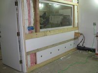
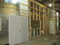
The first thing is to decide how you want it framed.The walls I'm building now have the FG in the center core. This allows a vapor retarder on both sides of the FG. I do not believe in total vapor barriors with sandwich walls or roofs. the moisture must be able to move both ways. I have cut walls open that I built this way years later and they were dry and there was no sign of mold.The bottom plate needs to be 6 1/2 " wide. You can rip it out of a 2x8 or build it up with 2 2x4's,ripping one down to3" and screwing them together with 6" deck screws. A 2x4 sill seal is used,centered under the sill. I do this because sill seals do not really seal the sill airtight due to the unevenness of the concrete. I will squirt expandable foam into the 1 1/2" gap on each side later.This will make an airtight seal.

Now a regular 2x4 stud wall is built,centered on the 6" bottom sill.I use screws and PL adhesive when putting the 2x4 sill on top of the 6" sill,once again to prevent air leaks. I use torx head deck screws because my hands are shot and dont work hammers anymore,plus, I can make any needed adjustments w/o destroying the wall pulling nails.Ny doors or windows should be set into the 2x4 wall now. I set the doors so that the brickmold is 1 1/2" out from the studs and windows flush with the 2x4's.

This is an interior wall that will be heated on one side all the time and heated on the other side ocasionally. If it were an exterior wall in a post barn you would build the 2x4 wall between the posts and against the wall girts. Pics of this method tomorrow.
 

Attachments

  • IMG_1702.jpg
    IMG_1702.jpg
    137.1 KB · Views: 473
  • IMG_1699.jpg
    IMG_1699.jpg
    136.6 KB · Views: 525
OP
T

trbomax

Well-known member
Joined
Mar 21, 2010
Messages
2,556
Location
starvation lake,mi.
Since there is no top plate, the tops of the 2x4 studs are slid between the truss carriers and securred with screws or nailed from both sides.
 

Attachments

  • IMG_1703.jpg
    IMG_1703.jpg
    133 KB · Views: 467
OP
T

trbomax

Well-known member
Joined
Mar 21, 2010
Messages
2,556
Location
starvation lake,mi.
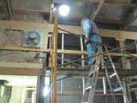
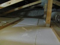
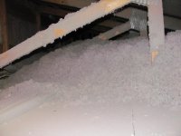
I want to jump ahead to the cieling build here. This is a section of cieling ready to have the cellulose blown in. I build in sections so that the cellulose can be blown at right angles to the trusses to a depth of 16 -18 inches. The foam dam isolates the area directly above the furnaces. I only blew 8" in there because I may need to acess the area later ( there are 2x8's to walk on ) and I'm not comfortable with cellulose blown directly around chimneys.This area is also above the "ocasionaly heated" part of the building so the high R value would be overkill anyway.We will discuss the foam between and under the trusses when I start the next section and can show what we are doing.

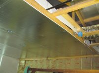
If you look at the one pic that shows the underside of the actual roof you can see the "polar wrap" ,foil side down, that was put down before the roof steel. It is taped on the top side. This is very important because it eliminates any sweating under any of the steel and creates an air seal around the building . It is 3/8" foam with a perforated foil bonded to one side and perforated plastic on the other. It is a moisture retarder,not a moisture barrior. It is reflective insulation as well,meaning that the foil faces the heated area and reflects heat back to its source. It carries a small R value of 1.5 but thereflective quality is the big reason for useing this as opposed to tyvac or the blue/red foam building wraps. They are fine for air intrusion, but are not reflective.

edit) for clarification,the first pic in this series shows the ceiling area ready for whatever final covering will be used,in this case liner steel. The last one shows the underside of the actual roof and as a bonus,the FG being placed in the core cavity of the wall described at the start of the construction.
 

Attachments

  • IMG_1709.jpg
    IMG_1709.jpg
    136.4 KB · Views: 293
  • IMG_1712.jpg
    IMG_1712.jpg
    139.7 KB · Views: 251
  • IMG_1707.jpg
    IMG_1707.jpg
    131.5 KB · Views: 280
  • IMG_1710.jpg
    IMG_1710.jpg
    142 KB · Views: 292
Last edited:
OP
T

trbomax

Well-known member
Joined
Mar 21, 2010
Messages
2,556
Location
starvation lake,mi.
One of the points of all this is that any air intrusion or movement thru the wall detracts from the insulation value and carries with it our mortal enemy,moisture vapor. This air movement must be prevented at all costs and preferably in multiple layers within the panels. Obviously,I'm not in a hurry to finish building this because this is so labor intense. Ive been building this way ( over the years) to try and create the best system and I realize that it is totally impractical unless you aproach it from that perspective.
 
OP
T

trbomax

Well-known member
Joined
Mar 21, 2010
Messages
2,556
Location
starvation lake,mi.
I managed to get 4 hours today without anything to do so nancy and I cranked up the vintage insulation blower and puffed 12 bales of cellulose into the cieling cavity shown a few posts earlier. That one is done so we can begin to do the sheet foam in the next 2 truss cavities. Tomorrow is looking pretty good for some wall work too!
 

Attachments

  • IMG_1718.jpg
    IMG_1718.jpg
    137.8 KB · Views: 162
  • IMG_1719.jpg
    IMG_1719.jpg
    133.2 KB · Views: 214
OP
T

trbomax

Well-known member
Joined
Mar 21, 2010
Messages
2,556
Location
starvation lake,mi.
Only had time today to finish the wood for mounting the steel and get a couple pieces of foam in. Some of the screws and washers will be removed once I weld it all together with spray foam. Ive got a road trip for a couple days so nothing will get done untill next week.
 

Attachments

  • IMG_1728.jpg
    IMG_1728.jpg
    138.1 KB · Views: 140
OP
T

trbomax

Well-known member
Joined
Mar 21, 2010
Messages
2,556
Location
starvation lake,mi.
I made some decent progress today. In pic 1729 the larger voids in the foam were welded with spray foam. In 1732 the expanded foam is trimmed flush.In 1735 the wall section is ready for the foil faced foam wrap.Any cracks or gaps left after pic 1732 were filled with latex painters caulk. The latex caulk is water based and does not "go after" the foam like a solvent based caulk. This basically makes the wall air tight and the addition of the foil faced 3/8" foam wrap with taped joints is additional insurance.
 

Attachments

  • IMG_1735.jpg
    IMG_1735.jpg
    134.9 KB · Views: 265
  • IMG_1732.jpg
    IMG_1732.jpg
    133.6 KB · Views: 201
  • IMG_1729.jpg
    IMG_1729.jpg
    138.9 KB · Views: 186

MG David

Well-known member
Joined
Apr 14, 2009
Messages
192
Location
Warwick UK
This is very interesting. To help me follow your description of the outside wall 3 layer construction could you add a cross sectional diagram of it.

Thanks
 
OP
T

trbomax

Well-known member
Joined
Mar 21, 2010
Messages
2,556
Location
starvation lake,mi.
I dont have a scanner that works,I need to just buy a new printer /scanner and be done with it.

The other side of the wall will be done the same way. If looking at a section from the outside in it would be:

1) outer steel sideing

2) 3/8" foil faced foam with the foil faceing inward,all joints taped

3) 1 1/2" foam between the outer wall girts,all seams either caulked or welded with spray foam from a can

4) either a 2x4 or 2x6 stud wall built between the posts depending upon which way the posts are oriented,with the appropriately sized FG batts or faced FG. If faced the faceing would be on the warm (heated) side.

5) Inside 2x4 wall girts are put on the wall to attach inside wall covering,but they must be staggered in such a way that they are not directly across from the outside wall girts. Of course the bottom one,which would be a treated 2x6, would have to be oppisite the outside girt.

6) 1 1/2" foam is fit between the inside girts from # 5 and caulked or welded as done in #3

7) 3/8" foil faced foam over the entire wall,just as in #2

8) inside wall covering of choice,in my case 1/2" sheet rock. You must screw the rock and be very carefull not toscrew it so tightly that it compresses the inside foam,not hard to do if you are carefull.

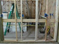
In this series of pictures its an inside wall or partition built between 2 shops in the same building,one side heated and AC all the time ,the other only heated as needed.I started with step # 4 in this case.

The interior ceilings are a bit different, the final steps on the ceiling panels were slipped in the earlier posts,but as soon as this wall section is done we will be moveing on to a ceiling section,so the whole process,in proper order, will be documented.

I hope this makes sense to you!

edit) If done correctly, this method will result in only a very small,somewhat direct thermal transfer where the girts are fastened to the studs and posts. There is no direct thermal transfer point because even the attachment points are covered on both sides with the 3/8" foil faced foam which has a r rateing of 1.9. If you want to increase this part of the R rateing this foam is avalable in 1/2 and 3/4 inch as well . I have used the 1/2 " material in the house construction but not with steel sideing.This is actually the first time Ive used the 3/8" material.

It also will be almost 100% free of any wind or air penetration,something that is very hard to do with post construction.
 
Last edited:

MG David

Well-known member
Joined
Apr 14, 2009
Messages
192
Location
Warwick UK
Thanks for the additional information. I don't know the term Girt. Is it a horizontal bit of wood or is it vertical like the normal framing in a stud wall.
 
OP
T

trbomax

Well-known member
Joined
Mar 21, 2010
Messages
2,556
Location
starvation lake,mi.
In post building construction a "wall girt" is the horizontal 2x4 that connects the posts and what you attach the sideing to. On a roof they are called "purlins". I dont know where the terms actually came from.
 

Huberte

New member
Joined
Nov 23, 2011
Messages
1
Hey Trbomax first of all thanks for sharing your experience with us, i really like the wording of your dad "if you wanted something you should either build it yourself or be personally involved" I totally agreed with him. I like your work too,keep it up dear.
 
OP
T

trbomax

Well-known member
Joined
Mar 21, 2010
Messages
2,556
Location
starvation lake,mi.
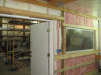
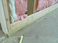
I finally got some time to work on this some more.I am now on the inside of the wall. The fiberglass core has been touched up and then the interior frameing finished. In the pic showing the detail at the floor you can see the ledge that the foil wrap,drywall,and pine paneling will sit on to keep it from contacting the concrete. I got some foam installed and was interupted again!
 

Attachments

  • IMG_1793.jpg
    IMG_1793.jpg
    134.7 KB · Views: 196
  • IMG_1794.jpg
    IMG_1794.jpg
    139.1 KB · Views: 172
  • IMG_1795.jpg
    IMG_1795.jpg
    138.3 KB · Views: 176

swharris

Well-known member
Joined
Jan 10, 2010
Messages
403
Location
So. Cal.
I can't ad to the building suggestions, but I can highly recommend the Lexmark Pro901 as a very good all in one printer/scanner/fax. Wireless printserv too. The best part is the low ink costs.
 
OP
T

trbomax

Well-known member
Joined
Mar 21, 2010
Messages
2,556
Location
starvation lake,mi.
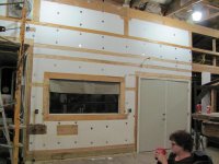
Well I dont need a new printer so on with my shop construction. The exterior of the shop wall is now covered with reflective foam. At the bottom where it meets the floor of the high bay shop,I installed treated 1" backers so that the base board can be installed The base is bent up from coil and provides a 6" ledge for the wall steel to sit on.So,this area is now ready for the steel panels.
 

Attachments

  • IMG_1804.jpg
    IMG_1804.jpg
    136.5 KB · Views: 138
  • IMG_1805.jpg
    IMG_1805.jpg
    144.3 KB · Views: 142
OP
T

trbomax

Well-known member
Joined
Mar 21, 2010
Messages
2,556
Location
starvation lake,mi.
I'm going to jump inside the room now and work on another 8' of cieling.It can only be put up in 8' sections because thats as far as I can shoot the celulose insulation.
Here the 2" foam has been attached to the rat runs with deck screws and 2" washers.A 2x4 is then screwed to each side of the lower truss chord. This gives the 2" foam a ledge to sit on and provides a large (8 1/2" ) surface to attach the reflective foam and then the steel cieling panels to. Another 2x4 is attached between the truss chords,this way the 2" foam is well supported as it must carry the wieght of the blown in cellulose. The areas around the boxes for lights and fans are filled with spray foam and then trimmed flush.
 

Attachments

  • IMG_1799.jpg
    IMG_1799.jpg
    139.1 KB · Views: 87
  • IMG_1801.jpg
    IMG_1801.jpg
    145.3 KB · Views: 95
  • IMG_1797.jpg
    IMG_1797.jpg
    141.4 KB · Views: 100
OP
T

trbomax

Well-known member
Joined
Mar 21, 2010
Messages
2,556
Location
starvation lake,mi.
Now the reflective foam can be attached and taped. 18 to 20 inches of cellulose is blown in above the foam giveing a total r value of about 70.

The 6" foam dam thats attached to the truss at the open end of the sectionis only to prevent the cellulose from spilling out and is removed as the next section is built.

The reasoning for putting the 2" fom up and sealing it,then the reflective foam and tapeing it is that it will retain the blown insulation in the attic area thus preventing it from sifting down thru the steel panels which as we know is not very air tight. The two layers of foam also prevent free air movement up from the room and into the blown insulation without creating a vapor barrior,only a vapor retarder. The attic space is not totally "cold" and subject to condensation because there is also a reflective foam layer under the roof panels.
 

Attachments

  • IMG_1800.jpg
    IMG_1800.jpg
    141.1 KB · Views: 94
  • IMG_1803.jpg
    IMG_1803.jpg
    140.8 KB · Views: 94
Last edited:
To avoid these ads, REGISTER NOW!
OP
T

trbomax

Well-known member
Joined
Mar 21, 2010
Messages
2,556
Location
starvation lake,mi.
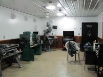
With 16' of ceiling done i am going to turn my attention to the exterior wall on the other side of the room. This is a 2x4 stud wall that has horizontal girts on the outside,filled with 1 1/2" foam inbetween,then covered with the reflective foam building wrap and all joints taped. The exterior of the building is steel attached in the conventional manner. The cavities between the studs were then insulated with r 13 fiberglass faced . Now I will begin to build up the inside wall girts starting at the floor.A treated 2x6 is set in warm roof cement and screwed to the 2x4 bottom plate and the lower edge of all the studs. Then the 1 1/2" ledge is installed , also set in warm roof cement. This ledge will hold the reflective foam,drywall,and then the pine paneling 1 1/2 " up off of the concrete floor.
 

Attachments

  • IMG_1807.jpg
    IMG_1807.jpg
    138.3 KB · Views: 87
  • IMG_1806.jpg
    IMG_1806.jpg
    138 KB · Views: 84

Big-Foot

Well-known member
Joined
Jan 30, 2005
Messages
1,951
Location
Midlothian, TX
Fascinating thread...

Structure-wise, You build a lot along the same lines as I do. I have always been miffed with vapor barriers though and would love to find a good source of information on them..

Studs and quality.. I am having one heckuva time finding studs that are actually dry and straight.. Seems like easily half of the 2x4 studs I buy are relatively straight, but 2 or 3 days later, they've turned into propellers.. 2x6's are not as bad, but I still toss 10-15% of them or use them for scrap work..

What are your experiences in that regard?
 
OP
T

trbomax

Well-known member
Joined
Mar 21, 2010
Messages
2,556
Location
starvation lake,mi.
I dont buy lumber at the box stores. The 16' 2x4's & 6's that I'm useing now on the last 5 or 6 posts have been stacked inside my high bay for about 2 years as they are the left overs from building my wifes shop room. Even the treated ones are straight w/o any wind. I get my lumber from a real yard over in Alden Mi. and try to figure what I will need for a long enough time that I buy enough for a delivery. Otherwise I go get it with one of the trailers.
 

rburke65

Well-known member
Joined
Nov 10, 2007
Messages
12,349
Location
Canfield, Ohio
Ok....whats "cheap o foam"? Is this the foil faced ISO type insulation? And what is a rat run? Is that the 2x4 that runs perpendicular to the truss on top of the bottom cord?
 
OP
T

trbomax

Well-known member
Joined
Mar 21, 2010
Messages
2,556
Location
starvation lake,mi.
A "rat run" is the 2x that runs at right angles to the bottom truss chord. Tha truss drawing will show how many and where the truss engineer wants them. When building the way that I am here,I add several more so I have something to attach my cieling foam too. Its also important when building this way to buy trusses that are rated for a lower chord dead load,not all of them are.

Did I post "cheap o foam" ? None of it is cheap,some types are less expensive than others. For this building I'useing polystyrene bead foam,which is the cheapest way to go because it is after all a shop,and because of the large quanity thats required for this size building. On the houses though I have always used either the blue or foil faced urethane boards.
 

rburke65

Well-known member
Joined
Nov 10, 2007
Messages
12,349
Location
Canfield, Ohio
So do you suggest that I do put some type of foam board under the steel? This shop is to have 12' side walls, 8/12pitch, full attic for cold storage, but only the shop area will be insulated.
 
OP
T

trbomax

Well-known member
Joined
Mar 21, 2010
Messages
2,556
Location
starvation lake,mi.
Definitly use a FOAM wrap under all the steel. The product I've been useing is made by Polar Industries Its available in 1/4",3/8" and 1/2". I use the 3/8. Its faced with reflective foil on one side and a plastic film on the other. Both sides are perforated with tiny holes to allow them to function as a vapor retarder. They are 4'wide and fan folded every 2' The actual r is only 1.9 but the reflective foil placed twoards the warm side will yield results far in excess of what you would expect of r 1.9. Run the seams from top to bottom,not side to side,and tape them useing the foil tape supplied by Polar. I have found that spraying the tape joint with 3M # 77 adhesive before putting the tape down will double the stickeyness of the tape. Squeegie the tape out with a plastic spreader. Your building will NEVER sweat if you do it this way and will be 95% wind proof. The quality of the tape joints is important because any condensation that may form under the steel is kept out of your building by the wrap and tape joints. Take your time with the wrap job. Fasten it down with 3/4" cap nails.
 
OP
T

trbomax

Well-known member
Joined
Mar 21, 2010
Messages
2,556
Location
starvation lake,mi.
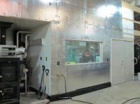
The first 16' of the machine shop room is ready for drywall. This first pic is the outside of the room,it will be steel sided. Today I cleaned up and reorganized things so that we can build the next 16'. Here the sill plates have been set between the posts. they are set in the hot roof cement and attached to the 2x6 treated form board that was left imbedded in the concrete when we poured the main shop slab.
 

Attachments

  • IMG_1840.jpg
    IMG_1840.jpg
    138.9 KB · Views: 122
  • IMG_1842.jpg
    IMG_1842.jpg
    135.6 KB · Views: 115
  • IMG_1844.jpg
    IMG_1844.jpg
    141.5 KB · Views: 111
OP
T

trbomax

Well-known member
Joined
Mar 21, 2010
Messages
2,556
Location
starvation lake,mi.
I got the stud wall sections roughed in yesterday and am putting the electric in today.
 

Attachments

  • IMG_1846.jpg
    IMG_1846.jpg
    138.6 KB · Views: 88

racer1

Well-known member
Joined
Dec 31, 2008
Messages
82
Location
Columbus wi.
Turbo, You could have just used SIP panels to achieve the energy efficiency you are looking for. I built my 3000 sq ft house with them. I just did a 5 yr ave. of my heating costs. $625 per year, On Propane. including hot water..And thats in Wi. The panels are easy to assemble, and are very cost effective...Its like living in a coleman cooler. I had to install a air to air heat exchanger, so I wouldn't suffocate in it!...They are That air tight....

Jim
 
OP
T

trbomax

Well-known member
Joined
Mar 21, 2010
Messages
2,556
Location
starvation lake,mi.
electric is in,fg insulation in,window is blocked in.the non conforming extension cord splice is to power up my diesel fuel pump outside,had to do something untill this is done!
 

Attachments

  • IMG_1847.jpg
    IMG_1847.jpg
    139.5 KB · Views: 73
  • IMG_1849.jpg
    IMG_1849.jpg
    135.1 KB · Views: 65
  • IMG_1848.jpg
    IMG_1848.jpg
    136.8 KB · Views: 65
OP
T

trbomax

Well-known member
Joined
Mar 21, 2010
Messages
2,556
Location
starvation lake,mi.
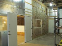
Ive not had time to do much on this for a month or so,spent 2 weeks in the hospital with a C difficile infection and that really kicked my ***. Anyhow all the cieling panels are up and the cellulose blown in the attic. we have started to put up the the rest of the reflective foam on the walls and seal it up.Its rather labor intense because each layer of foam has to be caulked and sealed air tight for maximum effect.The next step will be drywall for the walls.
 

Attachments

  • IMG_1931.jpg
    IMG_1931.jpg
    146.4 KB · Views: 51
  • IMG_1932.jpg
    IMG_1932.jpg
    148.5 KB · Views: 48
OP
T

trbomax

Well-known member
Joined
Mar 21, 2010
Messages
2,556
Location
starvation lake,mi.
Finished up caulking and troweling the foam wrap today. Got it all sealed up with tape too,so tomorrow I can start hanging drywall.
 

Attachments

  • IMG_1956.jpg
    IMG_1956.jpg
    144.7 KB · Views: 39
  • IMG_1953.jpg
    IMG_1953.jpg
    149.5 KB · Views: 36
  • IMG_1955.jpg
    IMG_1955.jpg
    147.1 KB · Views: 34
OP
T

trbomax

Well-known member
Joined
Mar 21, 2010
Messages
2,556
Location
starvation lake,mi.
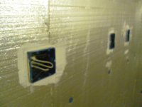
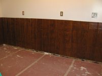
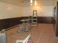
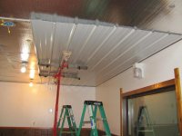
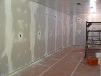
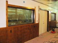
I figured the drywall,wood paneling and steel ceiling was pretty straightforward and not worthy of posting. I can look thru my pics and find some though.
 
OP
T

trbomax

Well-known member
Joined
Mar 21, 2010
Messages
2,556
Location
starvation lake,mi.
Here's a few.
 

Attachments

  • IMG_0177.jpg
    IMG_0177.jpg
    124.2 KB · Views: 71
  • IMG_0296.jpg
    IMG_0296.jpg
    137.2 KB · Views: 89
  • IMG_0019.jpg
    IMG_0019.jpg
    135.4 KB · Views: 66
  • IMG_0017.jpg
    IMG_0017.jpg
    134.7 KB · Views: 57
  • IMG_0046.jpg
    IMG_0046.jpg
    134.9 KB · Views: 74
  • IMG_2146.jpg
    IMG_2146.jpg
    140.3 KB · Views: 54
  • IMG_2145.jpg
    IMG_2145.jpg
    142.2 KB · Views: 63
To avoid these ads, REGISTER NOW!
Top Bottom