To avoid these ads, REGISTER NOW!

Upgrading Old Car Electrical System

Jehannum

Well-known member
Joined
May 3, 2012
Messages
1,368
Location
Albuquerque, NM
Jehannum, the housing/reflector and H4 bulb upgrade are also on my to-do list for the Imperial. Daniel Stern has moved from Cibie to Koito, so I will probably go with Koitos. Having said that, do you have a good source for Hellas in the 5.75" size?

(Side note - you have good taste in cars!)
I'm not sure what your setup is on the Imperial. On the GTO (which also has 5 3/4" lamps), the top two are dual filament (both high and low beam), and the bottom two are high beam only. It's been a minute since I bought them, but checking back through my emails, I got them through Summit. The hi/lo housings (h4 lamp) are 2850871, and the hi beam housing (H1 lamp) is H11425011.

I'm a steward of a wide variety of old slow cars, but thanks!
 
Last edited:
To avoid these ads, REGISTER NOW!

4EyedTurd

Well-known member
Joined
Oct 3, 2009
Messages
595
Location
Texas
I agree with the firewall connector. I used a different style connector but did the same on my 64
 

Monza Harry

Well-known member
Joined
Dec 29, 2018
Messages
1,433
Location
Windsor ON
Regarding DSLighting he still lists Cibie. I have the Cibie quad rectangular lenses from back in the early eighties (1983 IIRC)[bought locally long before DSLighting/internet], They cost my <$4.00/hr. self over $200 and I found them to be remarkable in performance [I also added 55/100W bulbs (H4- H1 bulbs from JC Whitney). They are pricey but from my experience worth every penny. I haven't heard of this other brand, so I have nothing of consequence to add there. Harry
 

gahrajmahal

Well-known member
Joined
Dec 12, 2008
Messages
2,538
Location
Cincinnati, Ohio
Rdoty, no matter the end end result, your Imperial will be a success based on the amount of research you are doing.

I too have a “C- Body”, the 1968 Chrysler 300 in my avatar. 10+ years ago I was in your shoes. Here is what I would do different.

I purchased a “Painless style” universal kit with the GM style fuse box. On our other car, a 1970 MGB I purchased two 10 fuse fuse panels with integrated ground buss. The reason? On the GM panel, you don’t know which fuses are Hot All The Time or HOT with the key (accessory). I purchased the wire separately for the MGB.

Today, I would still buy the Painless Wiring kit because buying the wire separately is expensive and there are no “on wire labeling “. I would then cut off the single fuse box and have the TWO Seperate Fuse boxes. One for “Hot all the time” and one for “Hot with the key”.

The fuse boxes I used on the MGB work great because the circuits being supplied with the power, also have individual ground wires returning to the matching fuse box. No more Mopar, ”ground through the body”.

Where to mount the fuse boxes? My current car has the GM fuse box mounted where the original one was so I have to stand on my head to change a fuse or work on the wiring. I would put the fuse boxes and relays in the glove box, possibly on a slide out panel for ease of assembly, and later, troubleshooting. My MGB has the fuse panel under a screw on cover that is usually covered with the folded down convertible top. What a PITA!

Lastly, I made a new to the car wiring schematic using machine wiring Ladder Logic. The idea is the “schematic” shows each circuit individually.

A wiring “diagram” tries to show where the wires go.

my ladder logic schematic

7BAAA4DE-E89B-47B5-BEDF-9F00C8004588.jpegAC39379E-538C-47F8-AB7F-8F414FF83651.jpeg
Lastly, I would loose the bulkhead connector. Since you are not staying factory correct. It is doing nothing for you but making a maintenance point you will always be suspicious of should your car have some unknown bugs in the future.

4A98E9E5-A2A8-42C8-B040-B5790C5F16B6.jpeg
 
Last edited:
OP
R

rdoty

ALLIANCE MEMBER
Joined
Feb 7, 2018
Messages
648
Location
Massachusetts
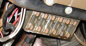
In the last post I replaced the factory firewall/bulkhead connector with a new more modern design. Like the bulkhead connector, the factory fusebox under the dash is is old and crufty.

Old Fusebox.jpg
Factory Fusebox​

Old Fusebox back.jpg
Back of old fusebox​

In addition to rust and using old style glass fuses, the factory fusebox only supports 6 circuits. This makes it difficult to add new electrical devices. In addition, some circuits are outside this fusebox. For example, the power windows and power seat are on a separate subsystem.

I’m replacing this with a Bussmann Series 15305-1 fuseblock. This includes dual power busses, space for 20 automotive fuses, and is designed for Metri-Pack 280 series connectors. An interesting aspect of the Metri-Pack 280 is that the connectors are the same size as automotive mini fuses. This means that automotive mini fuses can be plugged directly into Metri-Pack 280 female connectors. Using the Bussmann fuse block all you have to do is install a Metri-Pack connector onto the end of a wire and insert the wire into the fuse block and then you can plug in a fuse. Each power buss in the 15305 is capable of handling 100 amps and each fuse can be up to 30 amps.

Bussmann 15305 fuse block.jpg
Bussmann 15305 20 position Metri-Pack compatible fuse block​

The power busses are connected to the new bulkhead connector described in a previous post. It is currently using the factory wiring configuration; ultimately each bus will be supplied by 3 wires and capable of delivering 60 amps of power.

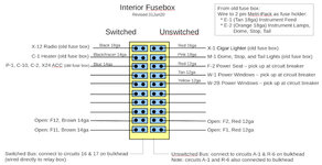
The process of wiring the new fuse block is the same as wiring the bulkhead connector: Start by building a diagram of circuits.

Interior fuseblock.jpg

Interior Fuseblock Circuits​

Using this plan I then went through the process of cutting the wires, adding labels and new connectors, and then plugging into the new fuseblock.

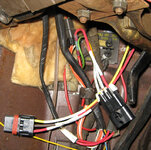
The power seat and power window wires were removed from the existing circuit breaker, terminated into a WeatherPack 3 circuit male connector, and three new 12ga lines were run from the new fuseblock (F-2, W-1, and W2B in the diagram above) to a WeatherPack 3 circuit female connector (shown here disconnected).

PowerSeatPowerWindowConnection.JPG
Power Seat and Power Window connections​

There are now plenty of extra circuits available. After connecting all of the factory wiring I added four additional circuits for future use. Each of these is 1′ long and has a Metri-Pack 280 series female connector installed. I can wire in new devices by putting a Metri-Pack connector on their power line, plugging it into one of the open wires, and adding the appropriate fuse. This avoids having to remove the fuseblock to get to the back side to add a new circuit.

If needed I can add an additional seven switched devices and five unswitched devices – this should provide plenty of expansion capability!

There was one special case: the instrument cluster lighting is on a dimmer circuit which changes voltage – this circuit can’t be connected directly to a power bus. I connected each side of the instrument cluster lighting to a Metri-Pack 280 series female connector and plugged in the specified 1 amp fuse. It is really convenient building fused circuits using the Metri-Pack system.
 
OP
R

rdoty

ALLIANCE MEMBER
Joined
Feb 7, 2018
Messages
648
Location
Massachusetts
Gahragmahal, Nice 300! What do you have in it, a 440? It looks like you have an MSD ignition. Are you running points or pointless?

Great job of recording the wiring schematics. I like to make these diagrams on the computer as it is easier to rework them there - for some reason I have to do a lot of re-design before I get something I'm happy with... So far I am largely staying with the factory design, which means that the factory wiring diagrams and circuit names still apply.

The wiring harness kits make a lot of sense in many cases. I decided to do an incremental upgrade of the wiring system, leaving many things in their original place but upgrading to more modern technology. For example, the fusebox upgrade I just described. Several more upgrades are in the pipeline - stay tuned!

The Internet makes it a lot easier to find things. Places like WireBarn let you buy packages of color coded GXL wire at reasonable prices. A package of 10 different colors of 14ga wire, with 25' of wire in each color, is $60. Where you need more wire, like black and red in 12ga and 14ga it is also reasonable - for example, 100' of 14ga GXL wire is $20.

A Dymo Rhino 4200 label maker prints on heat shrink tubing and makes it easy to label wires.
 

pooterguy

Well-known member
Joined
Jun 12, 2013
Messages
92
Location
USA on the road
After scanning through the Bodenzord tools and materials sections, I'm now assembling those that I already have on hand and completing second mortgage applications to purchase the others.

I have not come across any specific recommendations though for manufacturers and sources for the tin-coated wire and terminals or for the adhesive-lined heat shrink tubing mentioned elsewhere in this thread.
 
OP
R

rdoty

ALLIANCE MEMBER
Joined
Feb 7, 2018
Messages
648
Location
Massachusetts
Pooterguy, I feel your pain! Bodenzord has also cost me a lot of money. Not as much as Garage Journal, but still a respectable amount...

Waytekwire.com is my favorite source for terminals, especially the non-insulated ones I'm using now. Waytek is an industrial supplier and doesn't carry no-name junk components like some places do. No, not thinking Amazon here. Nope, nope!

Westmarine.com seems to have a good selection of marine wire, and their prices for 100' spools aren't too bad. I'm a bit cautious getting unknown brands of wire from Amazon, but the Ancor brand (well known, good stuff) sold and shipped directly by Amazon should be OK.

The adhesive lined heat shrink is commonly called marine heat shrink or marine grade heat shrink. I usually get it from Amazon or even Harbor Freight.
 

kerrynzl

Well-known member
Joined
Nov 8, 2013
Messages
5,054
Location
Tauranga, New Zealand
Pooterguy, I feel your pain! Bodenzord has also cost me a lot of money. Not as much as Garage Journal, but still a respectable amount...

Waytekwire.com is my favorite source for terminals, especially the non-insulated ones I'm using now. Waytek is an industrial supplier and doesn't carry no-name junk components like some places do. No, not thinking Amazon here. Nope, nope!

Westmarine.com seems to have a good selection of marine wire, and their prices for 100' spools aren't too bad. I'm a bit cautious getting unknown brands of wire from Amazon, but the Ancor brand (well known, good stuff) sold and shipped directly by Amazon should be OK.

The adhesive lined heat shrink is commonly called marine heat shrink or marine grade heat shrink. I usually get it from Amazon or even Harbor Freight.

In the early 2000's I built a "Stock" 3rd Gen Camaro for production racing.
I pull the whole harness out and unwrapped it [and zip tied it]

Then I traced and started removing every unneccessary wire [This ended up as a whole bucket full which was all rolled up as I was removing them] approx 12kg weight reduction.
20 years later I am still using this "colored" wire for various projects.

Go to your local U-Pull and pull a couple of harnesses from donor vehicles [pick-ups /wagons have longer wires]

On your car the only really need H/duty new wires for the main feed from the starter to the ammeter , from the ammeter to the Ignition switch and from the ammeter to the alternator.
Also maybe from the ignition switch 12v constant AND 12v switched to the respective buses in the fuse box will need to be upgraded also [if running decent lights, a/c or sound system]

All current flows both ways through the ammeter on old Chryslers [except the main battery to starter]

The ammeter usually can only handle about 35A to 40A of current [which is why they are feared and often bypassed] This 35A is enough for normal everyday use, but the problem occurs when a 60A - 100A alternater tries to charge a car that has flattened the battery

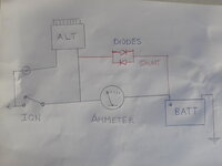
You make a "Diode Shunt" [Hybrid Shunt] that bypasses the ammeter when it is "maxxed out" but under normal circumstances the shunt is closed and the ammeter reads like normal. [and the Alternator is only charging enough for maintaining the battery]
Also if the ammeter fails the shunt will take the current and not leave you stranded on the side of the road.

They a really simple to make if you are interested.
 

Ohmthis

Well-known member
Joined
Jan 20, 2013
Messages
3,019
Location
Outside of Louisville KY
In the early 2000's I built a "Stock" 3rd Gen Camaro for production racing.
I pull the whole harness out and unwrapped it [and zip tied it]

Then I traced and started removing every unneccessary wire [This ended up as a whole bucket full which was all rolled up as I was removing them] approx 12kg weight reduction.
20 years later I am still using this "colored" wire for various projects.

Go to your local U-Pull and pull a couple of harnesses from donor vehicles [pick-ups /wagons have longer wires]

On your car the only really need H/duty new wires for the main feed from the starter to the ammeter , from the ammeter to the Ignition switch and from the ammeter to the alternator.
Also maybe from the ignition switch 12v constant AND 12v switched to the respective buses in the fuse box will need to be upgraded also [if running decent lights, a/c or sound system]

All current flows both ways through the ammeter on old Chryslers [except the main battery to starter]

The ammeter usually can only handle about 35A to 40A of current [which is why they are feared and often bypassed] This 35A is enough for normal everyday use, but the problem occurs when a 60A - 100A alternater tries to charge a car that has flattened the battery

You make a "Diode Shunt" [Hybrid Shunt] that bypasses the ammeter when it is "maxxed out" but under normal circumstances the shunt is closed and the ammeter reads like normal. [and the Alternator is only charging enough for maintaining the battery]
Also if the ammeter fails the shunt will take the current and not leave you stranded on the side of the road.

They a really simple to make if you are interested.
Great advice!
 
OP
R

rdoty

ALLIANCE MEMBER
Joined
Feb 7, 2018
Messages
648
Location
Massachusetts
Kerrynzl, that is a really creative way to get automotive wire! And an assortment of connectors.

A couple of people have mentioned a Diode Shunt. Can you post some details here? I took a different approach to the ammeter issue, but one of the reasons for posting here is to learn more from other people. In an upcoming post I will share the seven attempts it took me to get an upgraded alternator working correctly...
 

kerrynzl

Well-known member
Joined
Nov 8, 2013
Messages
5,054
Location
Tauranga, New Zealand
Kerrynzl, that is a really creative way to get automotive wire! And an assortment of connectors.

A couple of people have mentioned a Diode Shunt. Can you post some details here? I took a different approach to the ammeter issue, but one of the reasons for posting here is to learn more from other people. In an upcoming post I will share the seven attempts it took me to get an upgraded alternator working correctly...

I did this to my friend's Patina'd 54 Chevy pickup. This had a 350 and 700R4 conversion but he wanted the body /interior to be stock [including all the gauges working as normal]
We made a Diode Shunt [hybrid Shunt] from the Alt direct to the battery.
This is absolutely needed if using a 65a or larger alternator, the"Diode Shunt" bypasses around the ammeter.
[you can keep this in the engine bay ,and not crawl under the dash]


The Diode Shunt uses 2 "forward drop diodes" in opposing directions [parallel in this wire]
The diodes have a fixed value of voltage drop needed to open them, whereas the ammeter [acting like a resistor] has a progressive/non-linear voltage drop across it.
Below 35A there is less voltage drop across the ammeter than needed to open the diode, so the ammeter flows current.
At about 35A there is a point of equilibrium where internal resistance in the ammeter starts exceeding the forward drop value of the diode so the diode will flow the excess current.
This ^^^^ usually happens when the ammeter is "maxxed out" on its scale. [eg: after cranking over an engine]
Once the battery recovers [enough] and the charge starts dropping off the ammeter starts reading normal again


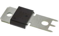
We mounted 2 x Vishay 150a rectifier diodes back to back on a piece of phenolic plastic [using common studs and spacers] Then mounted a wire with eyes each side on the studs.
1 wire goes to the Alt and the other to the Batt.
We hid the diode board insde an old "period correct" regulator box. [you should have one left over from the internal regulated Alt Conversion]

These diodes have a 1.13v forward drop which is about the same of voltage drop of an ammeter when its pegged out at 35A [either direction]

Also if the ammeter totally fails this will not leave you stranded on the roadside because All Voltage will flow through the diodes.


Vishay Diode.png

So to summarise............
Below 35A and the ammeter flows all the current and behaves as normal because there is greater forward drop via the diode, [so the gauge reads just like normal]
Above 35A and the voltage drop across the ammeter is the same as the forward drop of the diode, so the diode shunt behaves like an electrical "pressure bypass valve".

If you make the normal Resistor shunt [or a simple bypass wire] it will totally throw the ammeter off scale
 
Last edited:

Monza Harry

Well-known member
Joined
Dec 29, 2018
Messages
1,433
Location
Windsor ON
kerrynzl can you show a diagram and maybe a link or 2 for those diodes? I don't forsee an immediate need for this but I have been asked for help with many wiring questions/problems. Thanx! Harry
 

kerrynzl

Well-known member
Joined
Nov 8, 2013
Messages
5,054
Location
Tauranga, New Zealand
kerrynzl can you show a diagram and maybe a link or 2 for those diodes? I don't forsee an immediate need for this but I have been asked for help with many wiring questions/problems. Thanx! Harry

1736722911662.jpeg

You mount them parallel but 180 deg directionally [so they flow both ways]
I used 2 bolts and spacers to gap them , but they were mounted together phased at 180 deg needed to flow opposite directions.
These are 150A blocking diodes that only flow one-way but we are not using them for the blocking purpose! We were using the "forward drop" required to open them.

Ours was mounted on a phenolic board [old carb spacer] then hidden inside an old regulator box. with 2 wires from the box
It doesn't matter which wire was which because of the 180 deg orientation of the diodes.

The 2 wires can be mounted anywhere that bypasses the ammeter .Either direct to the ammeter posts OR direct from the Alternator to the Battery [which is what we did]
If the ammeter ever "chernobyled itself" the battery is still connected via the shunt to the Alt, then from the Alt to the ignition side of the ammeter.

link

I had a friend who was a "Gyro Gearloose" type that played with 60's Mopars that taught me all this. So it is perfect for the OP's imperial.
 
Last edited:

gahrajmahal

Well-known member
Joined
Dec 12, 2008
Messages
2,538
Location
Cincinnati, Ohio
Gahragmahal, Nice 300! What do you have in it, a 440? It looks like you have an MSD ignition. Are you running points or pointless?

Great job of recording the wiring schematics. I like to make these diagrams on the computer as it is easier to rework them there - for some reason I have to do a lot of re-design before I get something I'm happy with... So far I am largely staying with the factory design, which means that the factory wiring diagrams and circuit names still apply.

The wiring harness kits make a lot of sense in many cases. I decided to do an incremental upgrade of the wiring system, leaving many things in their original place but upgrading to more modern technology. For example, the fusebox upgrade I just described. Several more upgrades are in the pipeline - stay tuned!

The Internet makes it a lot easier to find things. Places like WireBarn let you buy packages of color coded GXL wire at reasonable prices. A package of 10 different colors of 14ga wire, with 25' of wire in each color, is $60. Where you need more wire, like black and red in 12ga and 14ga it is also reasonable - for example, 100' of 14ga GXL wire is $20.

A Dymo Rhino 4200 label maker prints on heat shrink tubing and makes it easy to label wires.
Rdoty, I do have the 440 and MSD ignition with a Mopar electronic (pointless) distributor. It has been very reliable for me. On my car I cut out all the wiring going to the under hood and all the wiring going to the back of the car (mostly lighting) and replaced it with the universal wiring kit. The only original wires are the gauges, power window switches and wiring and the power top and it’s associated relays. All that stuff is located in the driver kick panel, and all that stuff is where I still have the occasional glitch.

On my next wiring job, the MGB I thought the loose wire in spools would be the way to go. That is the job I recommended the two fuse blocks. The fuse block you found looks like a good alternative. I found that wiring the MGB used almost 800 feet of wire of various gauges by the time I got done. I thought sure 100 feet would do all the lighting circuits, but I kept running out then buying more. I also used a label maker to document the ends of the wires. Lots of time was spent doing that and sometimes undoing then redoing it. I would have saved loads of time not marking the wires and now many years later, it would be easier to troubleshoot.

Just saying, if I had to do it again today I’d buy the premarked universal wiring kit, cut off their fuse box and go with one like you bought. It would go faster. Your Imperial is much more complicated than my 300. Figuring out how much of the original wiring and components to keep will be your challenge.

As an example, since my Chrysler is a convertible, it is a fair weather car. In 2021 the heater core finally gave up the ghost and was spewing antifreeze fumes into the interior. To repair that, I removed the whole unit from under the dash. It is a gigantic unit including the AC, which has been disconnected for many years. So for now, I have no climate control at all in the car. The wiring for the original unit should I choose to have it repaired, or replacing it with a Vintage Air unit will require new circuits not easy to figure out since I am 10 years removed from wiring my car. If I remove the front seats, the installation will be semi- doable, but I am not getting any younger! So for now I only drive on warmer days.

Next up for my Chrysler? I will be replacing the convertible top cylinders and rebuild the pump. I plan to make a post about this once I get the job done. Will I rewire it too? Maybe…
 
Last edited:
OP
R

rdoty

ALLIANCE MEMBER
Joined
Feb 7, 2018
Messages
648
Location
Massachusetts
The last post covered updating the old fusebox under the dash. I’m now at the point where I can start working on adding a high power fuse/relay box in the engine bay that will both completely bypass existing wiring for high current devices as well as provide more power for the upgraded interior fusebox.

The fuse/relay box used was a Bussmann 15303 which provides five relays and ten circuits protected by fuse or circuit breaker. It is a weatherproof box which uses MetriPack 280 terminals and includes two 100amp internal buss bars.

Bussmann15303.png
Bussmann 15303 Fuse/Relay box​

Since the new fuse/relay box is roughly the size of the already removed AutoPilot, the plan was to install it where the AutoPilot used to be. Unfortunately you can’t just “put the fuse/relay box under the hood” – you need something to hold in in place: a bracket!

I had done a simple bracket for the interior fusebox, which I wasn’t completely happy with. The Bussmann box requires a fairly complex cut-out which I had done by hand. Crudely. You can’t see it under the dash, but the under hood location will be more visible. In addition, the under dash bracket was a simple bent flat sheet, while the new bracket really needed to be a box. Not only that, but a box that serves several purposes beyond simply holding the Bussman 15303.

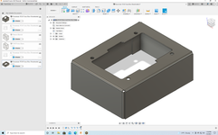
As part of my tremendously successful ongoing program of making simple tasks complex, I decided to design the bracket as a 3D Solid Model using the Autodesk Fusion 360 CAD program, unfold the 3D part into a 2D flat pattern using the Fusion 360 Flat Pattern module, and have it laser cut from steel by Send Cut Send. This is in contrast to the Cardboard Aided Design and hand grinder with cutting disk approach which is commonly used to design brackets.

Many years ago (I decline to say how many…) I was a Computer Aided Design – CAD – expert. I designed jet fighters (OK, I was a junior engineer on an 8,000 person design team) using a state of the art CAD system to design complex parts, mostly in sheet metal and composites. It has been years since I did any CAD work and I wanted to get back into it using the latest technology.

Fusion 360 is an incredibly powerful Solid Model based design and drafting system which is currently available to hobbyist under a one year zero dollar license – in other words “free”. To summarize my view of Fusion 360: WOW! Where was this technology when I was designing things for a living? A couple of tiny nits: Fusion 360, like all powerful software, has a learning curve. Solid modeling is very different from the wire frame based systems I learned on. And I’ve forgotten most of what I used to know…

After a few weeks of fighting Fusion 360 I had an initial design to be bolted to the inner fender:

FuseRelayOriginal.png
Original bracket in Fusion 360
This design didn’t work – too big and there was no place to attach it to the fender. So, back to the “drawing board” and come up with a modified version:

FuseRelayV2.png
Revised bracket design​

It was incredibly simple (OK, simple the 5th time I tried to do it) to do this design in Fusion 360: Design the top surface with the cutout and then select an edge and specify how long this flange was. In the case of tabs on a flange, just select an edge of the flange and specify how long the tab was. These flanges could be edited, so I added 3/8″ holes to allow plug welding the flanges to the tabs after folding the metal part.

After completing the 3D design the 2D flat pattern was produced simply by picking the 3D model and executing a single Unfold command:

FuseRelayFlatPattern.png
Flat Pattern with bend lines​

One interesting trick: the actual steel part doesn't have any bend line markings on it. I added a couple of 0.050" holes on each bend line. These holes tell me exactly where to bend the part.

With the design done it was time to send it out for fabrication. Send Cut Send is basically a “sheet metal print shop” which uses a laser cutter to cut precision parts out of steel, stainless steel, aluminum, copper, brass, titanium plastic, carbon fiber composite, wood, and other materials based on customer electronic design files. Sheet metal is a bit of a misnomer – they can cut metal up to 1/2″ thick! They can handle anything that can be cut out of flat stock, and are set up to produce from one to several thousand copies of a single part.

Send Cut Send has an interesting business model: they have a fully automated price quoting system to price per part with a $29 minimum order. They have fully automated all of their processes and they buy materials in large enough quantities that you can often get complete finished parts for less than what it would cost you to buy the raw materials!

I uploaded the flat pattern and started a new order specifying 22 gauge (0.030″ thick) steel. Hmm, the part is going to cost $9.37. I can order either one part or three parts for the same $29 minimum charge. Decisions, decisions… OK, three parts it is!

A few days later a package showed up with the parts ready to bend up.

SendCutSend.png

Sheet metal parts from SendCutSend​

With three parts I could afford to screw up two, so I grabbed the top part and started building up a prototype. First, bend the flat parts into the final box:

FuseRelayFoldedBox.jpg
Folded Fuse/Relay box​

“Plug weld” means welding through a hole to the metal behind it, and is a powerful tool for working with sheet metal. I forgot to turn on the gas in the MIG welder for the welds on the right – they are complete garbage. The welds on the left, with gas, are much closer to what they should be.

There were many details to work out on how and exactly where to mount the box, wire routing, and grounding. Mistakes were made — I mean “several options were explored in order to determine the best final approach”.

That description is way to simple. The reality was THE ****** BOX DIDN’T FIT NO MATTER WHERE I TRIED TO PUT IT! No matter what I tried, something was in the way! <Calm down, calm down…> The engine bay of the Imperial is surprisingly small. The area where I needed to put the box in was cris-crossed with lines, hoses, wires, boxes, and assorted parts. Not to mention THE FREAKING HOOD HINGE WHICH LOOKS LIKE IT IS OUT OF THE WAY UNTIL YOU TRY TO CLOSE THE FREAKING HOOD.

Ahem. After trying many different approaches I finally succeeded in finding a location that would work and built additional mounting brackets to actually support the box.

FuseRelayBoxInstalled.png
Finished fuse/Relay box wired and installed​

After getting something I was happy with the good elements were transferred to the second part which was then folded, welded (this time with gas), finished, and painted. Here is the finished mounting box with the fuse/relay box installed:

FuseRelayTestAssembly.png
Finished bracket with fuse/relay box​
 

Ohmthis

Well-known member
Joined
Jan 20, 2013
Messages
3,019
Location
Outside of Louisville KY
I’ve heard of send cut send before. I have used inventor in the past and have wanted to try fusion 360, but have yet to do anything (read too lazy to get after it). I love the modern approach at designing the bracket also.
 
OP
R

rdoty

ALLIANCE MEMBER
Joined
Feb 7, 2018
Messages
648
Location
Massachusetts
After figuring out all the details around mounting the fuse/relay box it was time to fill it. My approach to making electrical connections has evolved significantly. This will be familiar to many people – most of them will know more about wiring than I do!

The early days​

For many years these were my preferred tools.

OldElectricalTools.jpg
Stripper/Crimper, cheap terminals, primary wire and lamp cord/zip cord​

The only wire I knew was primary wire or hookup wire, purchased at a high price in short rolls from big box stores, or lamp cord. A cheap pair of pliers style tools served to both strip wire and crimp connectors. And the connectors were purchased in convenient cheap assortments.

The wiring pliers were a nuisance for stripping wire – it was far more difficult to get a good strip than it should have been. Also, it was difficult to get good crimps with them. The cheap crimp connectors were light weight and in many cases marginal. The plastic was badly crushed getting a crimp – and you couldn’t tell if you got a good crimp. And they simply looked cheap! Just looking at wiring done with these tools made you think it was a hack job. Often because it was a hack job!

InsulatedTerminal.jpg
Insulated **** Connector​

Despite all this, these were my tools for forty years.

The Transition​

The combination of the Imperial restoration and a dedicated workshop has lead to a dramatic upgrade in my tools. It has also lead me to learn more about what tools and techniques are available, resulting in significant improvements in my knowledge and skill in many areas. I’m not going to claim to be good, but I will claim to be less bad!

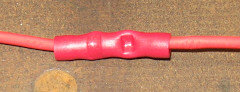
One of the first things electrical I learned about was heat shrink connectors. The cheap connectors I was familiar with did a poor job of sealing, and the only thing holding the connection together was the (often poor) mechanical crimp. The heat shrink connectors were more expensive, but provided a much better seal, a better mechanical connection, and a more professional appearance. But you were still crushing the plastic to make a crimp.

HeatShrinkButtConnector.jpg
Heat Shrink **** Connector, as crimped and shrunk​

Revelation​

The real revelation came when I read the Bodenzord blog series of articles on DIY Bussmann RTMR Fuse Block. This introduced me to a new world of parts, tools, techniques, and sources for materials: GXL automotive wire, Weatherpack and Metri-Pack sealed connectors, Bussmann fuse blocks, real crimpers and automatic wire strippers. The credit card came out and I’ve never looked back!

Terminals​

I’ve spent a lot of time talking about corrosion in automotive wiring. The car companies addressed this 30 years ago with sealed connectors which dramatically improved electrical reliability. These connectors have water tight male and female housings, rubber gaskets between the male and female housings, and rubber seals where the wires go into the housings. If water can’t get in it won’t corrode! The connectors crimp both to the bare end of the wire as well as to the insulation, providing a more secure connection.

There are many different styles, but the Bodenzord article recommended the Weatherpack and Metri-Pack connectors which have been widely used on many US cars and which are available at “reasonable” cost. You can get them online from industrial distributors such as Waytek, from Amazon, and from Ebay. You have to be careful with Amazon and Ebay as they are filled with cheap knockoffs, so I mainly buy them from Waytek.

The Metri-Pack 280 series is especially versatile as the female connectors can be directly used with mini-ATA fuses and micro relays. Among other applications, the Bussmann 15XXX series fuse blocks are directly wired with Metri-Pack 280 connectors. This makes it easy to build complex electrical systems. Metri-Pack 280 can handle up to 30 amps of power.

Metri-Pack 280 requires many components: both male and female terminals for various gauges of wire as well as male and female shells and retainer clips for different numbers of terminals. One, two, three, and four terminal shells will cover most uses. You will also need sealing rings for various gauges of wire.

MetriPack280Connectors.jpg
Metri-Pack 280 connectors, 1-4 terminal. Terminal pins and seals at bottom.​

Metri-Pack can quickly get expensive. I decided to build out a custom kit using parts from Waytek as they have some of the best prices for quantity purchases. Waytek has minimum quantities for many of their parts; this can make life a bit complicated when putting together an order. For some parts, like Female Tangless Terminals for 12-14ga wire (used in mass quantities with Bussmann fuse blocks) you really want to order 100-200 at a time. Wiring a single Bussmann fuse box will use 40+ connectors – plus the number consumed for changes and mistakes… Since you will generally have a connector on each end of each wire the numbers quickly add up.

For other parts, like 4 terminal shells, it is difficult to justify ordering 25 at a time. In any case, when assembling a custom kit for working with Metri-Pack 280 it is more cost effective to order what you need than to buy one of the pre-packaged kits.

Wire​

With connectors chosen, what wire to use with them? Car companies specify GXL and TXL wire because the insulation handles high heat, is oil resistant, and resists mechanical abrasion. TXL has thinner insulation and is more flexible while GXL is tougher. I’ve standardized on GXL.

GXL is hard to find and expensive – unless you go online. Even then you are often looking at 500’ or 1,000’ rolls – this gets expensive really fast when you want to put together a foundation of colors and wire size. For working on automotive electrical harnesses in is reasonable to have 6-10 colors of wire in multiple gauges. Do the math and you are quickly looking at 30+ rolls of wire!

Fortunately there is Wire Barn who offer packages of 25’ rolls of GXL wire in 6, 8, 10, or 11 different colors and in sizes ranging from 8ga to 20ga. Multi packs in 12ga, 14ga, and 16ga provide a great starting point for repair work and building wire harnesses. As you use them up you can either replace the colors you use or just buy another multi pack. Add some 100’ rolls in red and black in 10ga, 12ga, and 14ga and you are ready for just about anything.

WireBox.jpg
Wire Box: GXL wire in 18GA to 10GA​

Wiring Tools​

I bought a pair of Klein automatic wire strippers to try out. Ten minutes into my first wiring project using these I was asking “why didn’t I get these 30 years ago?!?” Stick the wire in the tool, squeeze, and you have a perfect strip every time. Strongly recommended!

AutomaticWireStripper.jpg
Automatic Wire Strippers​

Looking into better crimpers I discovered ratchet crimpers. These do a better job of crimping and are more reliable and consistent than pliers style crimpers. Ratchet crimpers are available as frames which hold a variety of crimping dies – which means that you actually have the proper tool for each type of terminal you are crimping! Many different models are available at different price points.

Astro Tools has a good reputation for quality and their 9477 set covers most types of terminals you will encounter. Add in a set of dies for Weatherpack/Metri-Pack and you are ready to go. Speaking of Weatherpack, you will also want a Delphi Packard crimping tool (especially valuable for crimping sealing rings onto the wire) as well as a Weatherpack pin removal tool and a Metri-Pack terminal removal tool.

RatchetCrimpers.jpg
Ratchet Crimper with dies, Automatic Wire Stripper, and WeatherPack Crimper​

Multimeter​

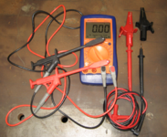
You absolutely have to have a multimeter for working on cars. After years with cheap multimeters I finally treated myself to a decent automotive meter – an Actron CP7677. In addition to the usual volts, resistance, and current, this meter also measures RPM and dwell angle.

The best addition to a multimeter is a good assortment of Test Leads - or perhaps an assortment of good test leads – with probes, clamps, extensions, and alligator clips. Also valuable are jumpers and extensions which allow you to temporarily connect circuits.

Multimeter.png
Multimeter with test leads

TestLeads.png
Assorted test leads and jumpers​

Non-Insulated Connectors​

At this point I was happy with the Weatherpack and Metri-Pack terminals but still didn’t like the insulated **** connectors and ring connectors – not even the heat shrink versions. I had read recommendations for non-insulated connectors so I decided to try them.

Non insulated connectors crimp better than insulated – with no chance of damaging the insulation – so this is a good starting point. After crimping you cover them with heat shrink tubing. Even better, cover them with marine heat shrink tubing, which is lined with an adhesive that melts and bonds to the wire jacket for a water-tight seal. Marine heat shrink tubing is available in different colors, allowing you to match it to the wire. The end result is less bulky than insulated connectors and has a more professional look.

After using them for a while I’m sold on non-insulated connectors and ratchet crimpers. About the only place I’m now using insulated connectors is for quick and dirty temporary jobs like building a test harness. You will be totally shocked that the best place I’ve found for high quality non-insulated connectors in reasonable quantities is Waytek…

CrimpConnectors.jpg
Crimp Connectors​

  • Top: Insulated **** connector and insulated spade connector.
  • Middle (red): from left: insulated heat shrink connector, non-insulated **** connector with red marine heat shrink tubing, and non-insulated ring connector with red marine heat shrink tubing.
  • Middle (black): Metri-Pack 280 female connector with ring seal.
  • Bottom: heat shrink label.

Final Thoughts​

While it has involved an investment in tools, connectors, and wire, I’m much happier with the results of my current wiring efforts. Using these tools and techniques produces wiring that is more reliable, has higher capacity, and is easier to work on than what shipped from the factory 60 years ago. In the past I was actually somewhat embarrassed about how my wiring jobs looked. Now I’m rather proud of how the Imperial is turning out. Even better, I’m no longer afraid to tackle new wiring or to troubleshoot electrical problems!
 
To avoid these ads, REGISTER NOW!
OP
R

rdoty

ALLIANCE MEMBER
Joined
Feb 7, 2018
Messages
648
Location
Massachusetts
With the location and mounting of the new fusebox resolved the next step is to fill up the fusebox.

The plan is to completely replace the existing under hood wiring harness with all new wires. Everything from the new bulkhead connector forward is being replaced – and upgraded. In addition to installing new wires, I’m increasing the size of the wires: 18ga is replaced with 16ga, 16ga is replaced with 14ga, 14ga is replaced with 12ga, and 12ga is replaced with 10ga. This is probably overkill, but there is very little cost difference in going one size larger on wire.

The process for building the new harness is straightforward. It is also time consuming and tedious…

To start, mount the new fusebox and measure the distance from the bulkhead connector on the firewall to the fusebox. This is the length of the new wires to the fusebox. As this will ultimately be a large stiff bundle of wires it is critical to get the length right.

Remove the new fusebox and take it over to the workbench. Dig out the carefully planned wiring diagrams that show where everything will be connected in the fusebox and how the wires are arranged in the bulkhead connector.

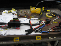
WiringWorkbench.png
Workbench with new wiring harness, old wiring harness, and tools​

The new Bussman 15303 fuse/relay box has two power busses. One bus is used to provide all power – it supports 10 fuses and is rated at 80 amps which should be more that adequate. The other bus is used to ground pin 85 on the relays; this is a low power application, but simplifies wiring.

Wiring the relays requires four connections: power, load, signal, and ground. Power goes from the power busbar through a fuse to the power side of the relay and then from the load side of the relay to where it is being used. The original power for each circuit is now used merely as a signal to the relay.

The first step is to wire a 12ga jumper from a fuse to the power side of the relay (pin 87) for all five relays. Wiring it this way means that the relay is protected by the fuse. Since the relays are the most complex part of the new harness they are wired first. The Bussmann box has considerable flexibility and can be wired with or without relays.

The original headlight wiring is a joke. Power for all four high beams was run through a single 16ga wire. A long run of 16ga wire, going through the headlight switch. Even if this were capable of safely carrying the current, the voltage drop through this tiny wire greatly reduces the brightness of the headlights. According to Danial Stern Lighting a 1 volt drop reduces light output 30% – going from the rated 12.8V to 11.5V reduces a 1,000 lumen headlight to 693 lumens. Going down to 10.5V takes the headlights down to a mere 510 lumen – a loss of 1/2 of available light!

The original headlights were 35 watts. Running the 4 Hi beams would be 140 watts or 11 amps. New headlights typically draw 55 watts or higher, with 65 watt high performance bulbs readily available. The headlight system needs to be designed to handle 260 watts with minimal voltage drop. And without burning up the headlight switch – at 12.8V, 260 watts is over 20 amps! 16ga wire is rated for 10 amps, meaning that it is marginal for the original bulbs and too small for modern bulbs.

The new design uses relays with a dedicated wire directly from the relay to each headlight. The original plan was to also have a dedicated ground for each headlight, which would require five wires to each side (two headlights per side): hi beam 1, hi beam 2, low beam, ground 1 and ground 2. A four wire connector is easier to fit through the holes, so the design was modified to hi beam 1, hi beam 2, low beam, and ground. To compensate for this the ground wire is now 12ga for two headlights instead of 16ga for four headlights.

14ga wire is plenty to power the headlights, especially with the short run from the relay to the headlights. Looking through my wire supply turned up longer rolls of 12ga than 14ga. OK, overkill it is – 12ga for all the headlights!

Time to start wiring. The old wiring harness was placed on the workbench next to the new fusebox as a reference. Using the low beam headlights as an example: The low beam is identified as circuit L-4, a black wire installed in pin C of the bulkhead connector.

Since this is now just a signal wire, a piece of 16ga black wire is cut to the length previously measured from the new fuse box to the bulkhead and labeled (with shrinkwrap labels) as “L-4 LO BEAM”. Actually, this wire is cut a few inches long; we will trim all wires going into the bulkhead to the same length at a later stage. A MetriPack 280 connector is installed on one end and plugged into the fusebox on pin 86 of relay 1. The wire is routed out of the fusebox where it will later be gathered into a bundle.

Next, go to the old harness and measure from the location of the fusebox to the left side headlight connector. Cut a black 12ga wire to this length and label each end “L-4 LO BEAM 1”. Cut a white 12ga wire to the same length and label each end “HDLT GRND 1”. Might as well take care of the HI beams at the same time, so measure and cut two pieces of red 12ga wire and label them “L-3 HI BEAM 1″ and L-3 HI BEAM 2”.

Since there are four headlights on the car, measure the length to the right side headlights and cut and label the four wires.

For the Low beams there are two wires going to the relay. Using a heavy duty **** crimp connector, the two wires are stripped, wrapped together, and crimped into one side of the connector. A short 12ga jumper wire is crimped to the other side of the **** connector and the whole thing is sealed with marine grade heat shrink tubing. A MetriPack 280 connector is crimped onto the jumper wire and plugged into pin 87 on relay 1.

The Hi beams are done the same way. You can’t run four 12ga wires into a **** connector, so a small weather proof buss bar is used instead.

A grounding buss is mounted inside the mounting box for the fuse box. The headlight grounds and relay ground are connected, along with a 10ga wire going to the chassis ground bolt.

One challenge with upgrading power is that the Weather Pack bulkhead connector only supports 20 amps per pin. Of course this implies that two pins will support 40 amps… So, run two wires with 20 amp fuses from the new fuse box to the bulkhead. On the inside, run two wires from the bulkhead connector to the unswitched power buss on the interior fusebox. Bingo, 40 amps of power is now available from the fusebox!

Switched power is done the same way using two relays. The ignition circuit, J-2, which provides power to the ignition coil, is live whenever the car is turned on. This circuit is tapped to provide a signal to relays 3 and 4. These relays are connected to the bulkhead connector, providing 40 amps of switched power to the interior fusebox.

One of the side effects of being forced to remove the AutoPilot cruise control is that the three control wires for cruise control are no longer needed and could be removed from the bulkhead connector. This made it possible to directly connect the power seat and power windows directly to the new fuse box. I had previously added a MetriPack 280 connector to these circuits. New wires were run from this connector to the bulkhead, and new wires run from the bulkhead to the new fuse box. The result is that power for these high current devices now comes directly from the new wiring.

This takes care of the power circuits. There are also several other wires going through this part of the harness, such as side marker and turn signals, horn, and windshield washer. These wires are traced and a new wire is cut to length, labeled, and routed through the fuse box.

After checking and double checking that all wires for this part of the harness have been added it is time to sleeve the wire bundles using braided sleeve. The wire bundle is run through the appropriate size sleeve and the ends of the sleeve secured with heat shrink tubing or electrical tape. Both wire bundles going into the fuse box are quite large – they barely fit through the 1″ grommets in the box.

FinishedFuseRelayBox.png
Finished fuse/relay box​

After sleeving the wires the connectors are added. The bundle going to the bulkhead connector is straightened out and all the wires cut to the same length. Weather Pack connectors are crimped onto the ends of each of these wires.

It is finally time to start updating the bulkhead connector. A circuit from the new fuse box is chosen such as L-4 LO BEAM. The pin for this circuit in the bulkhead connector is identified and removed using a Weather Pack pin removal tool. The new pin from the new fuse box is inserted into the bulkhead connector and locked in place. Finally, a piece of yellow masking tape is placed on the old pin – this lets me know that I have finished working on this circuit. As I may have mentioned, I get confused easily and there are 22 pins in the bulkhead…

After connecting all the wires going to the new fuse box it is time to answer the most important question: did I cut the wires too short? The bulkhead and the new fuse box mounting are fixed, and the wiring bundle is short, stiff, and has no give. If these wires are short I will have to go back to ground zero and start over again. No pressure…

The whole bundle of new harness and old harness are picked up and the new fuse box is mounted in place. Go to connect the bulkhead connector:

And the wire bundle is 1″ too long. Perfect! Absolutely perfect! This is just the length needed to provide a little bit of give in the bundle so it can be arranged out of the way, makes it easy to connect, and isn’t long enough to cause other problems. And there was much rejoicing!

FuseRelayBoxWithBulkheadConnector.png
Fuse/relay box connected to Bulkhead​

Remaining steps include finishing the headlights, turn signals, parking lights, horn and windshield washer. After that is wiring the engine, including ignition, HVAC, and sensors. Last is doing the new wiring for the Alternator.
 

no704

Well-known member
Joined
Apr 27, 2016
Messages
5,229
Be very careful to NOT get any brake fluid on any of that!!
 
OP
R

rdoty

ALLIANCE MEMBER
Joined
Feb 7, 2018
Messages
648
Location
Massachusetts
The last post described the installation of the new fuse/relay box and rough wiring. The next step was to complete the headlight wiring by installing a Weather Pack 4 pin connector on the new wiring harness.

I may have slightly overstated the status of the headlight wiring… While the new wiring is indeed 12ga, it doesn’t run all the way to the headlights. There is a separate run of wire from the main harness to the headlights. Recall that one of the defining features of 1961-1963 Imperials is the podded headlights.

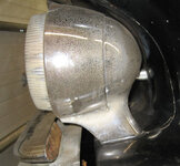
HeadlightPodFront.jpg HeadlightPod.jpg


The wiring runs up from the bottom of the headlight through the base, into the pod, and then through a connecting bar between the two pods. There is minimal space for the wiring – getting four 12ga wires in here will be a real challenge. So I decided to punt on this for the moment by re-using the existing headlight wiring and building an adapter between the new wiring harness and the existing headlight wiring. The headlight wiring will be updated when I have the headlights out for painting or when I send the pods out to be re-chromed.

While re-using the existing 16ga three wire setup for the headlights isn’t ideal, the remaining 16ga wire is short and the upgrades to the rest of the system help a lot.

The existing headlight connector is a 3 pin Packard 56 connector. Of course I have 1 and 2 pin Packard 56 connectors, but no 3 pin. Not a problem – cut the existing connectors off of the old wiring harness leaving a 3″ pigtail. Then crimp Weather Pack connectors onto the ends of the old wires and install in the mating shell for the new wiring harness. As long as everything is opened up, go ahead and spray the old connectors with contact cleaner. Viola, or maybe even voila, and the headlights are plugged in and working.

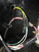
HeadlightConnector.png

In this picture you can see the four 12ga wires of the new harness going into the sealed Weather Pack connector and the three 16ga wires from the original harness (white, black and red) going to the headlight. Also shown are the green and yellow wires to the parking and turn signal lights.

The headlights are now substantially brighter than they were before. Thanks to the relays and new wiring I no longer have to worry about the old wiring or the old headlight and dimmer switches. The headlights had already been upgraded from the really old incandescent bulbs to the somewhat less old sealed beam halogens. A planned upgrade is to replace these with modern H1/H4 lights – this will probably be done when the headlight pods are rewired.

A couple of other notes on the headlight wiring: 35 amp relays were used; this makes sure that the relay is not the weak point of the system. Even using 65 watt bulbs, the four high beam headlights will only be pulling a total of 20 amps. 100 watt HI beams could be a problem, but even then they could be split across two relays. And 100 watt bulbs would probably melt the pods!

This particular Bussmann fuse/relay box was chosen because it supports circuit breakers as well as fuses. The headlights will use these automatic resetting circuit breakers for maximum reliability and safety.
 

ez-duzit

Well-known member
Joined
Jun 24, 2013
Messages
5,104
Location
Marina del Rey
...While re-using the existing 16ga three wire setup for the headlights isn’t ideal, the remaining 16ga wire is short and the upgrades to the rest of the system help a lot.
...
Those short 16-gage pigtails won't be a problem as voltage drop over such a short distance is negligible.
 

kerrynzl

Well-known member
Joined
Nov 8, 2013
Messages
5,054
Location
Tauranga, New Zealand
The existing headlight connector is a 3 pin Packard 56 connector. Of course I have 1 and 2 pin Packard 56 connectors, but no 3 pin. Not a problem – cut the existing connectors off of the old wiring harness leaving a 3″ pigtail.

You can de-pin these connectors with a needle. [then use a new terminal /wire into the same connector plug/block]
I de-pin connectors often just to thread the individual wires through grommets

Here in NZ we have "Narva" connectors that are very similar but only available in white
 
OP
R

rdoty

ALLIANCE MEMBER
Joined
Feb 7, 2018
Messages
648
Location
Massachusetts
After finishing the headlights it was time to track down why the heater blower motor wasn’t working. The symptom was a blown fuse as soon as I pressed any of the heater buttons. No power means the motor doesn’t work.

After changing several fuses I confirmed that the problem was in the blower circuit. It looked like something was creating a dead short. This could be from the new wiring harness, or I could have pinched something when re-installing the heater plenum.

The speed control for the blower motor goes through a big resistor mounted on the firewall in the engine bay. I started the underhood troubleshooting by unplugging one of the wires from the resistor.

Umm, why does this wire say NEUTRAL SAFETY SWITCH???

Krud. In the new wiring harness both of the wires for the blower resistor plus the wire for the neutral safety switch are all brown and come out of the wiring harness at the same location and have the same connectors on the end.

This is why it is critical to READ THE FREAKING LABEL (RTFL) when you are connecting devices!

Yup, the wire connected to the neutral safety switch says HEATER BLOWER MOTOR.

Connect the wire labeled NEUTRAL SAFETY SWITCH to the neutral safety switch. Now plug the wire labeled blower motor into the blower resistor. Hmm, its a bit too short. OK, wire up an extension with a new plug and plug it it.

Now to check the blower motor: No blown fuse! And the heater blower runs at low, medium, and high speeds. There wasn’t any rejoicing this time – I was too annoyed with myself for making such a stupid mistake.

The last thing was to try to start the car and make sure the neutral safety switch still worked. The Imperial fired up immediately, so that part is still good.

All that work labeling all the wires and then I don’t pay enough attention when actually hooking everything up. At least the problem was obvious when I finally looked. Grumble.

On a side note: If you are going to be doing a lot of electrical work it is a good idea to buy fuses in bulk. The retail price of automotive fuses can be over $1.00 each. Or you can get them for less than a dime by ordering 50 or a hundred at a time – for example, 20 amp mini fuses for eight cents apiece. Since it is easy to go through several fuses when tracking down a problem (at least for me…) it is good to have a box full of fuses available.

The next job is to figure out why the alternator isn’t charging.
 
OP
R

rdoty

ALLIANCE MEMBER
Joined
Feb 7, 2018
Messages
648
Location
Massachusetts
In the last post I fixed a stupid mistake in connecting the new wiring harness, allowing me to get back to things that actually improve the car. I’ve described how much of the original factory wiring is too small and what the new wire harness does to include heavier wire – for example, replacing a single 14GA wire for all four headlights with a separate 12GA wire for each of the four headlights.

Most of the wiring so far has involved 16GA, 14GA, 12GA, or 10GA wire. This wire is available in multi-color bundles from places like Wire Barn. Electrical fittings, terminals and connectors are readily available, as are crimping tools.

Wire heaver than 10GA gets expensive, requires special tools for crimping, and is harder to work with in general. It is needed in fewer places, making it less attractive to keep a stock of heavy gauge wire. The easiest way out is to order finished individual wires from places that specialize in this.

I’ve had good lock with Genuine Dealz, so I figured out what wires I needed and placed an order. I have no idea where the name comes from, but they have a good reputation for building high quality cables. They utilize marine grade wire, which is solid copper wire with the individual strands coated with tin – this makes the wire much more corrosion resistant than uncoated wire. It is also more expensive, but “buy once, cry once” applies. They can crimp a variety of connectors on the wire and cover then ends with marine grade heat shrink tubing – this is heat shrink tubing that has an adhesive lining which makes the connections water tight.

Genuine Dealz has a very nice web ordering system: you specify the gauge of the wire, the color, and length. You then specify what fittings you want on each end and whether or not you want heat shrink tubing on each end. The system interactively calculates the price at each step along the way. Prices are quite reasonable for what you get.

AlternatorBatteryWiring.jpg
Alternator and Battery Wiring​

The alternator got a major upgrade: The original alternator wiring consisted of a 12GA wire going to the ammeter in the dash, and another 12GA wiring going from the other side of the ammeter to the battery. With the new wiring harness this was temporarily changed to a 10GA wiring going directly to the battery. This was probably adequate, but it is being replaced with 6GA (the green wire in the picture above).

An interesting aspect of alternator wires is that they include a fusible link. This is basically a fuse built into the wire. It is needed because a failure mode of alternators can cause them to start producing several hundred amps of power. Another failure mode causes a direct short to the battery, with all the power the battery can produce flowing through the alternator wire. Either way you are looking at the potential for considerable damage to the electrical system and a likely fire. Instead of this happening the fusible link will burn out like a fuse and protect the rest of the system.

As an alternative to a fusible link you can add an actual fuse to the alternator circuit – typically an 80 amp or 100 amp fuse for a 60 amp alternator. Or you can add a circuit breaker, which is what I did. An 80 amp marine circuit breaker is water proof and can be reset if there is a problem.

After placing the order I got a call from Genuine Dealz: it appears that they are having trouble getting wire in all colors. I wanted orange for the alternator wire but they didn’t have that. So I ordered green and then covered it with the black woven sheathing I’ve been using for the rest of the harness.

The next step was to replace the 10GA wire from the battery to the Fuse/Relay box with, you guessed it, a 6GA wire. The power bus in the Fuse/Relay box is rated for 80 amps, which would be a bit much for the 10GA.

The 10GA wire from the negative battery terminal to the chassis frame ground was also replaced with 6GA.

This took care of the light wiring. The factory 4GA cables for the starter motor were upgraded to 1/0. Between these very heavy 1/0 cables and a battery capable of putting out over 1,000 amps I don’t expect to have problems starting the 413, even when it is hot!

The last touch was the actual battery terminals. Standard battery terminals don’t work well when adding more wires to them and tend to be weak – I actually broke the old positive terminal clamp from the multiple connect/disconnect cycles during this wiring upgrade.

Military battery terminals are made for just this use case. They are much heavier than standard terminals and have a heavy 3/8″ bolt for connecting multiple cables to a single terminal. They were an obvious upgrade for the battery connections to support the new heavy duty wiring.

With all the upgraded wires installed it was time to connect the military terminals to the battery and see if things worked. After double checking the new wires – it would “embarrassing” to find out how the new 6GA cables hold up to the 1,000 amp battery… Nope, no ground wires were connected to the hot side of the battery.

Almost everything worked… Everything but the headlight HI beams. LO headlights worked fine but high beams were dead. Sigh. OK, dig out the voltmeter and start trouble shooting.

Bad relay? Swapping relays didn’t do anything. OK, pull the HI beam relay and check voltages. Supply voltage was good – but no voltage on the signal line from the HI/LO switch. Hmm, this was odd… I hadn’t touched anything that would produce these symptoms.

Or had I? I had removed the 22 pin main bulkhead connector to get extra slack on the wiring when working on the fuse/relay box. After pulling the bulkhead connector back off I noticed that the pin for the HI beam looked odd. Like it had been crushed…

Apparently I wasn’t careful enough with the bulkhead connector. Pull the HI beam pin out, replace it, and put the bulkhead connector back together. Carefully re-install the bulkhead connector and then check the headlights. LO beams – still good. HI beams – all four headlights now working. And there was much rejoicing!

Time for a test drive. All the gauges are working and the rest of the electrical system checked out. Check off another project completed!
 

pooterguy

Well-known member
Joined
Jun 12, 2013
Messages
92
Location
USA on the road
rdoty, slightly off the recently posted subjects - but my projects are WAY behind your own...
Do you have any experience with or opinion of Molex connectors?
 
OP
R

rdoty

ALLIANCE MEMBER
Joined
Feb 7, 2018
Messages
648
Location
Massachusetts
Pooterguy, which Molex connectors? I've used Molex connectors in computers, but haven't used them anyplace else. In computers they are one of the default connectors and have a good reputation.

Does anyone else have experience with Molex connectors for automotive applications?
 
OP
R

rdoty

ALLIANCE MEMBER
Joined
Feb 7, 2018
Messages
648
Location
Massachusetts
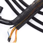
ez-duzit: This is the standard black polypropylene braided mesh that I'm using to cover all wire bundles under the good. The color doesn't have any significance here.

BraidedMeshSheathing.jpg

On the other hand, it is fair to call me out for using green for the underlying cable! There was a very limited selection of colors available when I ordered this one, but this was still a poor choice.
 
OP
R

rdoty

ALLIANCE MEMBER
Joined
Feb 7, 2018
Messages
648
Location
Massachusetts
Yes, that would be a good kit. Molex is a high quality manufacturer focused on industrial applications. If you can find it at a decent price I would not hesitate at all. A kit like that, some decent ratchet crimpers, and some marine heatshrink and you are good to go!
 

Jehannum

Well-known member
Joined
May 3, 2012
Messages
1,368
Location
Albuquerque, NM
Pooterguy, which Molex connectors? I've used Molex connectors in computers, but haven't used them anyplace else. In computers they are one of the default connectors and have a good reputation.

Does anyone else have experience with Molex connectors for automotive applications?
I wouldn't use them anywhere that might get wet, they aren't back-sealed.

That said, back-sealed connectors weren't common on cars until the early 1990s, so weigh the eventuality of corrosion making its way up your wires against the cost of proper back-sealed connectors like weatherpack/metripack.
 

Poolshark314

Well-known member
Joined
Jul 5, 2021
Messages
658
Location
MD
Nice job @rdoty ! I have done the ammeter bypass as well and it is well worth i t. Getting ready to try and replace my gauge cluster with a new digital one, so maybe I'll see what other upgrades I can address while in there
 
OP
R

rdoty

ALLIANCE MEMBER
Joined
Feb 7, 2018
Messages
648
Location
Massachusetts
Welcome to today's installment of Alternator of Doom!

In the last post we largely finished upgrading the Imperial wiring. But the story wasn’t done. Bypassing the ammeter leaves no way to know the state of the charging system, so I planned to add a voltmeter.

This led to buying a <$20 multifunction digital gauge that included a clock, inside and outside temperature, and a voltmeter. Trying this out on a test drive produced immediate concern – the voltmeter said 12.3V when the system should have been over 13 volts. This indicated that the system isn’t charging, and driving the car would just run down the battery. A deeper dive was clearly called for.

Time to grab the good multimeter and connect it to the battery. This showed 12.7V, a reasonable value. The cheap, straight from the Far East multifunction device was inaccurate – shocking! The next step was to fire up the engine. If the charging system was working the voltage at the battery should jump to 13.2-13.4V. With the engine running the voltage stayed absolutely flat – no change at all. Krud. The charging system was actually bad.

Three things could be bad: the voltage regulator, the alternator, or the wiring. And they were all new. In fact, the voltage regulator was an upgraded solid state regulator that should work better than the old electro-mechanical regulator.

Still, the symptoms looked like a voltage regulator. The fastest way to get a new one was through Amazon, so one was ordered. I still needed a voltmeter, so I also ordered a dual USB with voltmeter that plugs into the cigar lighter. The new regulator arrived, was installed, and no change. The new voltmeter seemed accurate when compared to the digital multimeter.

Again, krud. OK, check the alternator wiring against the service manual again. There are only three wires and it is straightforward; everything looks correct. OK, that leaves the alternator. While getting ready to order another new alternator (the alternator was replaced during the rebuild) I remembered that I had saved the old alternator. I was even able to find it. OK, install the old 35 amp alternator, verify that it works, and then order another 65 amp alternator.

Fire up the engine – and no change. Still no charging. Krud. The possibilities are two bad voltage regulators, two bad alternators, or bad wiring. I spent a couple of days checking everything – tracing the wiring, checking the wiring, jumpering around the wiring with direct connections, running various tests, and in general pounding my head against a brick wall.

While reading up on charging system tests for the 87th time I realized that I had done an alternator test wrong. The test is to connect the FLD (Field) terminal on the alternator directly to the positive post of the battery. If the alternator is good it will over-charge the battery, producing over 14V. You don’t want to do this for long, as it will destroy the battery and the alternator.

When I performed this test the first time I had left the wiring harness connected. This acted like a dead short, producing sparks and instantly heating my test wire. Thinking about it, this shouldn’t have happened. This time I disconnected the wiring harness from the alternator, connected a test wire, and started the engine.

With considerable fear I touched the test wire to the positive post of the battery – and nothing dramatic happened! OK, a good sign. Hold the test wire on the battery terminal and the voltage reading starts going up, quickly exceeding 13.6V and clearly charging the battery. Now this is a very good sign! It shows that the alternator is good, strongly suggests that the wiring is correct, and points a finger at the voltage regulator.

Next question: is the new 60 amp alternator also good? Time to re-install the new alternator and re-run the test. With the new more powerful alternator the voltage quickly exceeded 14V. With the alternator good and the wiring good, pretty much the only thing left is the voltage regulator.

Two bad voltage regulators? Shouldn’t happen. For the third voltage regulator I ordered a premium regulator from RockAuto. More expensive, but hopefully better quality.

When the third voltage regulator arrived I bench tested it with a regulated power supply. Unlike the other two voltage regulators, this one showed 12V on the output FLD terminal; the others showed 0V in this test. An encouraging sign, so time to install this regulator.

With the third voltage regulator installed I once again fired up the engine – and watched the digital multimeter rise to 13.3V! The charging system is working. And the USB/voltmeter in the cigar lighter is also showing 13.3V.

The only thing left was to confirm these results. The voltmeter showed a consistent 13.3-13.4V during a test drive, exactly what it should be.

This one had me tearing my hair out. I don’t expect to get two bad parts in a row – I don’t “expect” to get one bad part in a row! I learned more about testing alternators and voltage regulators, so should be able to figure out something like this much faster in the future. Another lesson is to order parts from reputable sources.

With the charging system working I can call the electrical upgrades done.

Update 1:​

The next morning I headed out on a longer test drive. Immediately after starting the voltage went to 15.3V and the voltmeter started saying “tilt”. Not good – this looks like the voltage regulator is shorted out. Pulled the car back into the garage, hooked up the good multimeter, and it was reading 15.6V at idle. Since this will fry the battery, the alternator, and what is left of the voltage regulator I started troubleshooting the charging system (again).

The voltage then went to battery voltage, like it was before I installed this new regulator. I checked across the IGN and FLD terminals and it showed an open circuit. The regulator is dead.

What is going on here??? Three bad voltage regulators? Mentally going through everything I had done I began to question how I tested this regulator. I had hooked it up to a bench power supply which could have put up to 10 amps through the regulator. In fact, this was likely – one of the resistors on the voltage regulator got so hot from the test that I burned my hand when I picked it up. Could I have almost burned out the regulator, leaving it good enough to work initially but damaged enough to quickly die? Unfortunately this seems like a distinct possibility… It looks like the only thing to do is try another regulator.

Update 2:​

The fourth voltage regulator arrived and I installed it. It looked perfect while running the engine briefly. So far so good… It was really hot this afternoon so I don’t feel like a longer test drive. Will try to get out tomorrow for a good run.

Update 3:​

On the test drive the next day the voltage went back above 15V again. Krud.

Time for more research. A recommended upgrade is to go to a later model electronic voltage regulator which Chrysler used in the 1970’s-1990’s. This later model regulator works with the new style alternator I had purchased, so I went ahead and ordered one.

Update 4:​

The new(est) voltage regulator arrived. It is wired differently than the older style voltage regulators, so I made a temporary test harness with the new wiring connections that would let me try it without making permanent changes to the existing wiring harness. With the test harness ready, I installed the new alternator and the new voltage regulator, connecting them with the test harness. After a careful review of the wiring I started the engine.

And watched the voltage immediately go to 17V-18V. Not Good! Quickly turn off the engine.

This is getting ridiculous! I’m getting frustrated and out of ideas. Back to the Internet for more research.

I found some articles that suggested this behavior could be caused by a short in the alternator field windings that control the output voltage. This can be tested by checking the resistance between the field terminals and the case of the alternator – this should be an open circuit with infinite resistance.

Get the alternator on the bench, dig out the multimeter, and start checking. Hmm, Field Terminal 1 to case is measuring 4 ohms. Field Terminal 2 to case is measuring 0.3 ohms. Could this be the problem all along – the new alternator is bad???

Time to order another new alternator. Might as well order another new voltage regulator while I’m at it. Just in case the alternator problem managed to fry the voltage regulator. Stay tuned for the next update!

Update 5:​

I ordered the new alternator and voltage regulator on Wednesday; supposed to arrive next Tuesday. Then got the order confirmation with new shipping information – now next Friday. Bummer, I didn’t want to wait that long. Thursday (yesterday) I got a package delivery email – and the new parts were on my doorstep! One day shipping as a (pleasant) surprise.

There are some indications that I might have originally received a new style alternator that was internally configured for the old style voltage regulators. Chrysler alternators were mechanically compatible over about a 30 year period – they all just bolt in. The switch to new style voltage regulator occurred in 1970. To make sure everything was new style I ordered an alternator and voltage regulator for a 1972 Imperial.

Time to repeat this familiar drill: pull out the old alternator, install the new alternator. Pull out the old voltage regulator, install the new regulator. Connect the wiring, including the test harness for the new style voltage regulator. Double check the wiring. Hook up the multimeter to check voltage. Check the wiring again. Start the engine…

And the voltage looked good. Encouraging, but we’ve been here before. Back the car out of the shop and head out on a test drive. This time the voltage stayed rock steady on 14.5 volts! This is at the high end of the normal range, but it is within the normal range and is expected at startup. Over a 30 mile test drive the voltage dropped to 14.4 volts and stayed there. When idling it would drop to 14.2-14.3 volts.

Things are looking good – this is exactly where the voltage should be. The next step is to do a permanent mount for the new voltage regulator and then replace the test harness with permanent wiring. Followed by another test run! Not that I’m paranoid or anything… Actually, at this point, I AM paranoid about the alternator and voltage regulator!

It looks like the underlying problem was a bad 60 amp alternator. This might have killed the voltage regulators, or it could have been something I did.

The engine is hot after the test drive so I will just put this job off until Monday.

Update 6: Success!​

The final step was to install the voltage regulator in its final position and replace the test harness with production wiring.

As seen in this picture there is little room for the voltage regulator and poor access. Despite this I was able to locate it and drill new mounting holes. I really need to get a right angle drill. And smaller hands…
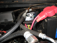
NewVoltageRegulator.png
New voltage regulator – the "silver" box​

The new voltage regulator requires two wires. I really didn’t want to run another wire – adding wires to a sleeved harness is a lot of work. The new voltage regulator doesn’t have the dedicated ground wire that the old one does – so why not repurpose the old ground wire as the new field wire? This simply required putting new terminals on each end of the wire – along with updating the labels on the wire so I won’t confuse myself in the future.

To ensure that the voltage regulator is well grounded I added a new ground wire from the updated chassis ground system to the case of the voltage regulator – this is the same ground that the headlights are using. I checked the grounding of the alternator to chassis ground and it was good, around 0.3 ohms.

With everything connected and the wiring double checked it was time for the first moment of truth. Fire up the engine and check the voltage. 14.5V-14.6V – just a touch high, but within specs.

I’ve been here before, so on to the real test – the test drive! After a good test drive, including Interstate driving, the voltage registered a steady 14.4V-14.5V. Again, on the high side but within specs.

I’m declaring success and moving on to the next project.
 
To avoid these ads, REGISTER NOW!
Top Bottom