To avoid these ads, REGISTER NOW!

Upgrading Old Car Electrical System

493mike

Well-known member
Joined
Jul 24, 2015
Messages
148
Location
mid Michigan
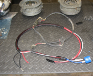
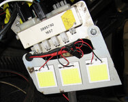
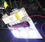
Sorta off topic but, electrons are involved! I am finishing up rewiring my 65 Belvedere with a Infinity Box system. It was a learning experience for sure. I used many Weather Pack connectors, extra relays, fuses, C.B.s, as well as lots of larger size cable. I purchased a product called No Ox to seal my connections (it is conductive grease). Much time was needed to sketch out wiring circuits and lots to redo some of my designs! I really enjoyed the whole process, so don't be afraid to jump into the electron pond!
Mike
www.infinitybox.com
IMG_2623.JPGIMG_1557.JPGSwitch Plate.JPG
 
To avoid these ads, REGISTER NOW!
OP
R

rdoty

ALLIANCE MEMBER
Joined
Feb 7, 2018
Messages
647
Location
Massachusetts
Nice! Hmm, you can actually get to things with the dash out. Much easier than crawling under it and contorting to reach awkward places!

Can you add some details about what is going on in the second picture? It looks like some serious - and seriously nice - fabrication work, but I can't tell what is what.

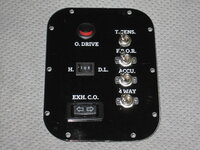
The switches in the last picture are rather tantalizing - what exactly do they do?

One suggestion: get a Rhino 4200 label maker and some different sizes of heat shrink label tape and use that to label all of the wires. I've found this to make a huge difference in wiring.
 

493mike

Well-known member
Joined
Jul 24, 2015
Messages
148
Location
mid Michigan
Nice! Hmm, you can actually get to things with the dash out. Much easier than crawling under it and contorting to reach awkward places!

Can you add some details about what is going on in the second picture? It looks like some serious - and seriously nice - fabrication work, but I can't tell what is what.
The 2nd photo is a panel in the trunk distributing power to the rear Infinity Box Master Cell and the stereo amplifier. See the large fuses between the cable lugs? It also includes power and ground terminal strips for trunk equipment.
The switches in the last picture are rather tantalizing - what exactly do they do?
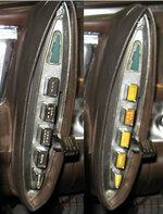
The switch panel mounts in my console below the shifter and uses a matching trim ring. Switches control: exhaust cut-outs, over drive, oil accumulator, 4 way flashers, fuel pump override, driving lamps w/halos, and DPDT temperature sensor toggle to allow a single gauge to check engine coolant or transmission oil.
One suggestion: get a Rhino 4200 label maker and some different sizes of heat shrink label tape and use that to label all of the wires. I've found this to make a huge difference in wiring.
Thanks for the replies fellas!
Mike
 
OP
R

rdoty

ALLIANCE MEMBER
Joined
Feb 7, 2018
Messages
647
Location
Massachusetts
A few weeks ago I went to dinner in the Imperial. It was dark by the time we left, making this the first time to drive the car after dark. To my surprise I had no dash lights! Making matters worse the headlights were aimed sharply down, giving me about five feet of visibility (slight exaggeration). Good thing that it was a fairly short drive home on roads I knew well!

When the instrument panel was rebuilt the dash lights worked fine, so this was completely unexpected. I hadn’t done anything to the instrument panel!

Or had I…

When working on the HVAC controls I had discovered that the lighting panel was unplugged. So I plugged it in and it glowed. One problem solved! Or was it “one problem solved?”?

The most common failure mode on electroluminescent lighting is for the power pack to get weak, causing the dash lights to get dimmer and dimmer. The power pack produces 200 volts of alternating current. The capacitors in these power packs dry out over time, and the driver transistor can fail. The extra load of the HVAC panel could be enough to kill the lights.

Fortunately there are companies who rebuild the lighting power packs. Unfortunately this is fairly expensive and takes months. Even worse is the difficulty getting to the power pack: it is mounted high up on on the drivers side sidewall behind the kick panel. It is completely buried behind wiring, control cables, the emergency brake assembly, and the huge brake pedal bracket. It is a major effort to contort yourself under the dash to be able to even see part of it – I have no idea how to actually get it out! And back in… I suspect that this power pack was the very first thing installed inside the car and everything else was built around it.

There are some people making new replacement power packs – compatible modules made with new technology. These cost about half as much as a rebuilt original module and claim to work better. So I took a chance and ordered one from Ebay. If this didn’t work I could always pull the original power pack and have it rebuilt. Assuming I could figure out how to remove and re-install the old one…

When the new module showed up the first step was to test it. I unplugged the wiring from the old power pack and plugged it into the new module – fortunately the wiring was relatively accessible. Time to double check connections, turn off workshop lights, and turn on the headlights.

The instrument panel remained dark.

Not unexpected, so turn the dimmer control. And there was light! The instrument cluster illuminated just as it was supposed to. “And there was much rejoicing”.

With the new module working it was time to mount it. The new module is much smaller than the original, so there was no point in trying to mount it in the same place. There was plenty of space on the side panel for the new module, so it was simply a matter of choosing a location and drilling a hole for the mounting screws.

Hmm, while in there I might as well add some soundproofing. I had saved the larger scraps of Noico sound deadening material and used these to cover most of the sidewall. After this it was simply a matter of installing the new driver module, connecting it, checking that the instrument panel lights still worked, and re-installing the kick panel. One task down!

The headlight problem was simple. I had replaced original rear springs with heavy duty springs which raised the rear end. Raising the rear end makes the headlights point down. Fortunately headlights are adjustable: remove three screws in the headlight trim ring, turn the vertical adjustment screw until they are the proper height, and then reinstall the trim ring.

Now I just need to get out at night and check everything out!

Update​

I got out at night and everything worked. Not quite as bright as I would like but usable.
 
OP
R

rdoty

ALLIANCE MEMBER
Joined
Feb 7, 2018
Messages
647
Location
Massachusetts
Sorta off topic but, electrons are involved! I am finishing up rewiring my 65 Belvedere with a Infinity Box system. It was a learning experience for sure. I used many Weather Pack connectors, extra relays, fuses, C.B.s, as well as lots of larger size cable. I purchased a product called No Ox to seal my connections (it is conductive grease). Much time was needed to sketch out wiring circuits and lots to redo some of my designs! I really enjoyed the whole process, so don't be afraid to jump into the electron pond!
Mike
493Mike, I took a quick look at the Infinity Box and it looks interesting. Can you write a post here or start a new thread describing your project in more detail? It looks like using the Infinity Box requires more upfront design (as you noted). I'm interested in your reasons for choosing this approach as well as your experiences in implementing it. Always more to learn!

Thanks,
Russ
 

493mike

Well-known member
Joined
Jul 24, 2015
Messages
148
Location
mid Michigan
493Mike, I took a quick look at the Infinity Box and it looks interesting. Can you write a post here or start a new thread describing your project in more detail? It looks like using the Infinity Box requires more upfront design (as you noted). I'm interested in your reasons for choosing this approach as well as your experiences in implementing it. Always more to learn!

Thanks,
Russ
I will try to remember to do so but, I want to power everything up to evaluate the system. Still out a few weeks.
Mike
 
OP
R

rdoty

ALLIANCE MEMBER
Joined
Feb 7, 2018
Messages
647
Location
Massachusetts
It is now time to deal with a sticky situation – specifically, power windows that stick going up and down.

Power windows are the among the worst cases for old car electrics – the motors require high amperage and are fed through long wires and small switches. Over time the window mechanisms become harder to operate, requiring even more power from the motors. At the same time the wiring degrades, reducing voltage available to the motor and making it work even harder. The result is that power windows simply don’t work well on old cars – when they work at all.

In my case one of the windows (drivers door, of course…) doesn’t work at all, two windows barely work, and the fourth window is slow and doesn’t always go all of the way up.

Part of the work on the doors includes cleaning and lubricating the window mechanisms. This certainly helps, but doesn’t go far enough to solve the problem.

Really solving the problem requires completely replacing the existing power window wiring with something that can handle the power requirements.

Relays will be used to provide power directly to the window motor – basically the same thing that was done with the headlights when they were upgraded. The existing switches still control the windows. But instead of handling the 20-30 amps that the motor draws, the switches will now trigger the relays and only have to handle less than 0.1 amps. The existing wiring and switches are easily able to handle 0.1 amps.

The window motor requires two relays – one for up and one for down – which makes the wiring somewhat more complex than the headlights.

Power for the relays will be provided by a new dedicated 12 gauge power line that is run directly from the relays to the fuse box. Power will now come from a shorter run of heavier gauge new wiring – the motor will now get full voltage and full power.

Since I’m paranoid – in other words, I have experience… – the relay upgrade will be done as a series of incremental steps with testing at each step. Thus the first step is to build a test harness to allow testing the window motors outside of the existing window wiring. This test harness will go through a series of modifications and upgrades as the build proceeds.

The initial test harness was simply two wires connected to the battery. There are two wires to the motor – I was pretty sure that the motor case is ground, and you apply +12V to one wire to go up and +12V to the other wire to go down. But it could also be reversing plus and minus between the two wires for up and down.

With the two wires connected to the to the battery, the negative wire was held against the motor case and the +12V wire was applied to one of the wires to the motor – and the window went down! +12V was applied to the other wire and the window went up. OK, motor wiring is confirmed.

Next a two way switch was added to the test harness. Technically this was a dual pole/dual throw momentary contact switch, also known as DPDT momentary contact. This allowed using the switch to control up and down on the motor. The test harness is long enough to reach from the battery to each door and to the workbench, making it easy to operate the windows either on the car or on the bench. This was convenient since you need to move the windows up and down to remove the glass. As previously mentioned I’m paranoid, so a fuse was also added.

Since the test harness will also be used to implement the new dedicated power wiring, a matching power connector was installed. The test harness can be used to directly power and control the window motor in the car or on the workbench as well as provide power to the relays.

PowerWindowTestHarness.png
Power Window test harness connected to a window motor​

With motor operation verified and the test harness ready to go it was time to build the relay setup. The first step was to lay out the design on paper, double check it, and determine how to connect the relay wires. I’m using Bosch style relays which have five wires – trigger/source, ground, power in, power out normally open and power out normally closed. Since the relay should provide power when the switch is turned on the normally open (NO) output is used and the normally closed (NC) output was sealed off.

The relays I’m using came with sealed sockets and pigtails – this makes it easy to wire them up. The good news is that the pigtail wires are color coded. The bad news is that the color coding didn’t comply with standards… Notes that include pin number, color, function, and wiring instructions kept me from becoming excessively confused when making the four relay packs (one for each window).
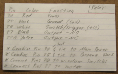
RelayWiringCard.png
Relay wiring card​

I wired up the relays on the bench – it is much easier to work on the bench, and it gave me the chance to double check everything before installing. Note the labels on the wires – this minimizes mistakes and makes it much easier to troubleshoot in the future.

WindowRelaysWired.png
Window Relays Wired. Note wire labels.​

The test harness and a voltmeter allowed complete testing on the bench. No mistakes were found in the wiring. OK, OK – no mistakes were found when the relay packs were ready to install in the doors…

The window motor was originally grounded through the door skin. Since it is very little additional work to run two wires instead of the planned one wire for power, a dedicated 12 gauge ground wire was added to each window. This ground ties directly into the upgraded grounding system under the dash and is bolted to the power window mechanism frame which is connected directly to the motor. This also provides a convenient high quality ground point for any other potential electrics in the door.

The new power and ground wires are connected to the relays using a waterproof Metri Pack 280 connector. The relays are sealed, and all wiring connections are sealed with marine grade heat shrink tubing – the result is that there shouldn’t be any corrosion in the power window system.

The motor originally used non-sealed Packard 56 connectors, which I replaced with more of the Metri Pack 280 connectors. When I cut the old connectors off and stripped the insulation, the wires were solid black with corrosion. Sandpaper and electrical contact cleaner cleaned up the wire ends and the new sealed connectors should prevent more corrosion in the future.

The test harness was plugged in to provide temporary power to the relays and window operation tested. It worked!

With everything ready to go I spent an hour or so making a bracket to mount the relays. I then tested window operation and watched the window hit the relays as it neared the bottom position. Actually I stopped the window just before it hit the relays. I’m getting paranoid about that sort of thing…

Studying the situation more, I decided that the relays could be mounted directly to the inner door skin. The relays were mounted in this new position, the window run down, and nothing hit. OK, one more problem solved!

PowerWindowRelaysInstalled.png
Power Window Relays Installed​

The window now goes up and down smoothly. It will need to be adjusted to fit the new weatherstrip I’m installing. This will probably be a nightmare; if it is I will do a post.

This process will be repeated for the other three doors.

I also need to finish connecting the new power wiring. As I do each door I’m running the new power and ground wires up to under the dash. The next to last step will be to connect all of the new power and ground wires and splice into the existing power window feed from the under hood fuse box.

The last step is to enjoy the new smoothly operating and reliable power windows!
 

no704

Well-known member
Joined
Apr 27, 2016
Messages
5,225
Short of putting limit switching on the windows, maybe just a 10A thermal breaker might be an idea? I used to be an auto glass tech, never could understand just stalling out the motors at the end of travel.
 
OP
R

rdoty

ALLIANCE MEMBER
Joined
Feb 7, 2018
Messages
647
Location
Massachusetts
Turns out that these window motors have thermal breakers built in. I discovered this when running a window up and down for trouble shooting and it stopped. Thought I had killed it! Did some digging and learned that this feature was built in.

Do new motors have thermal breakers?
 

Xti04

Well-known member
Joined
Nov 11, 2016
Messages
2,341
Turns out that these window motors have thermal breakers built in. I discovered this when running a window up and down for trouble shooting and it stopped. Thought I had killed it! Did some digging and learned that this feature was built in.

Do new motors have thermal breakers?
Most new motors are permanent magnet and the body controllers look for an amperage spike to set limits for travel and one touch functions
 
OP
R

rdoty

ALLIANCE MEMBER
Joined
Feb 7, 2018
Messages
647
Location
Massachusetts
Makes sense. Amazing what you can do with electronics! I'm somewhat amused that the Imperial has a grand total of six transistors - all in the radio - while modern cars have 100+ computers containing billions of transistors.
 

Swanny1953

ALLIANCE MEMBER
Joined
Jul 28, 2010
Messages
1,075
Location
Lucas, TX
OP, thanks for the excellent writeup and sharing of details. I wasn't aware of the Rhino label maker, but now have on enroute!
On your headlights, have you looked into the Holly RetroBrite lights (https://www.holley.com/brands/holley_retrobright/)? I have used them on 2 Corvette restomods and a 1952 Ford Woodie station wagon. Easy installation and the light quality is phenemonal.
A quick question - I have a 1966 Dodge Charger that needs much in the wiring arena. When did Chrysler stop routing all the power through the ammeter? Were they still doing this in 1966? I will be upgrading much of the wiring as the rotating headlight feature of these cars requires that the engin be at running speed to provide the power needed to rotate the motors, and will need to study up on the diode shunt solution if Chrysler was still running the power in this manner.
Thanks again for the terrific writeup and details of your project!
 
OP
R

rdoty

ALLIANCE MEMBER
Joined
Feb 7, 2018
Messages
647
Location
Massachusetts
Swanny1953, glad this helps!

Short answer: if your '66 Charger has a factory ammeter, all power is going through it. If it doesn't have an ammeter you are good to go. A bit of research indicates that 66-67 Chargers do have an ammeter. It looks like Chrysler used ammeters through at least 1970, possibly later for trucks.

The battery should have plenty of power to drive the headlight motor - if not, it sounds like you have a classic voltage drop situation and could use a wiring upgrade. You might want to start with grounds - make sure the ground strap connecting the engine block to the firewall is in good shape. If there was a problem with the battery to engine block ground cable you would have trouble starting. Also check how the motor is grounded.

Consider installing a relay for the headlight motor. If you do this the motor will get power directly from the battery/alternator and the existing wiring will just provide a tiny amount of switching power. Adding a Bussmann fusebox with relays connected directly to the battery would let you provide power through new large gauge wiring directly to each large power consumer. Note that this would bypass the ammeter; you would want to add a voltmeter to monitor the electrical system. Headlights, heater motor, and perhaps AC compressor clutch would be the biggest power consumers from the factory. If you have added an electric cooling fan or an electric fuel pump they should be directly powered.

It sounds like you are a good candidate for the shunt diode upgrade.

Thanks for the pointer to the Holley RetroBright headlights! I wasn't aware of these true LED headlight upgrades. Need to look at them closely.

On a side note, I used to have a '68 Charger. Great car; still miss it. I considered doing a '68-'70 Charger for this project but those are now well out of my price range!
 
OP
R

rdoty

ALLIANCE MEMBER
Joined
Feb 7, 2018
Messages
647
Location
Massachusetts
A common problem with older cars is inaccurate gauges. Perhaps the worst offender is the gas gauge, with many (most?) 1960’s Mopars having dead or wildly wrong gas gauges.

The fuel sender is a float in the gas tank that moves an electrical wiper over a wire wound resistor. In addition to mechanical wear, the fuel tank is a corrosive environment. When you can find a replacement fuel sender it often doesn’t work well with the gas gauge.

I had this problem with the Imperial. The gas gauge never read over 1/2 full, even with a freshly filled tank. When I removed the old sender it was so corroded it literally fell apart in my hands. Like many other parts for these old Imperials a replacement sender was hard to find.

Of course the new fuel sender didn’t work well with the gas gauge.

I was able to bend the float lever on the new sender to get it to read full when the tank is full. However, the gas gauge reads empty when the tank is still 1/4 full. This is much better than reading 1/4 when the tank is actually empty, so I have been living with it.

A recent email from the Online Imperial Club mentioned MeterMatch. This is a small electronic box that fits between the sender and the gauge in the dashboard and allows you to match the sender to the gauge.

MeterMatch.jpg
MeterMatch​

From their web site: “To calibrate MeterMatch, you first set the sender to a known value. For example, fill your fuel tank. Set the MeterMatch to program mode, then with the up and down buttons, make your gauge read what you want for that sender value. When you are satisfied with the reading, press the “save” button, and the value is remembered in the MeterMatch. Do the same process with the sender reading a value near the other end of its range, and you are done. MeterMatch interpolates from these values to make the gauge read proportionately at values above, below, and between the calibration values. It also has cardinal-point values stored inside that you can use if you know the resistance of your sender.”

If you are installing a new fuel sender you would temporarily connect it to the fuel gauge before installing it in the gas tank. Raise the float to its highest position and adjust the MeterMatch so that the gas gauge reads full, then lower the float to its lowest position and set the gas gauge to empty.

You can also set intermediate calibration points to make 1/4, 1/2, and 3/4 on the gas gauge completely accurate.

I haven’t used MeterMatch yet but it is a very interesting device I will probably add in the future. I’m mentioning it here in case anyone else needs it. And to be completely frank, so I can find the link in two years when I can’t remember it…
 

gahrajmahal

Well-known member
Joined
Dec 12, 2008
Messages
2,538
Location
Cincinnati, Ohio
Hey rdoty, I am liking all of your upgrades to your imperial and your detailed photos and explanations. I may duplicate your door relay setup as well as your headlamp relay setup. Did you provide a link for your relay/fuse panel?

For the fuel sender, my C body has a relay between the sender and gauge that slows down the reaction of the float bobbing up and down. Yours probably has this too. There is a solid state one available but is expensive.
 
OP
R

rdoty

ALLIANCE MEMBER
Joined
Feb 7, 2018
Messages
647
Location
Massachusetts
Gahrajmahal, thanks for the kind words! I just wrapped up installation of new weatherstripping and adjusting the window tracks. After some tweaking, invocation of strong language, and application of some dry silicone spray to make the new weatherstripping slippy not sticky, the windows are going up and down smoothly.

The fusebox is a Bussmann Series 15305-1. This has space for 20 fuses on two separate power busses. I configured it with one buss of unswitched power and one buss of switched power.

The fuse/relay box is a Bussman 15305-2-2-4. I'm using it as the primary distribution source for both switched and unswitched power for the whole car.

One of the best sources for information on all of this is the Bodenzord series on wiring. This was my introduction to the world of Metripack, Weatherpack, Bussmann, GXL, and modern wiring approaches. Strongly recommended!

I'm not familiar with a fuel sender relay. I don't see one in the factory wiring diagrams, so I suspect the Imperial doesn't have one.
 
OP
R

rdoty

ALLIANCE MEMBER
Joined
Feb 7, 2018
Messages
647
Location
Massachusetts
With the beautifully chromed headlight buckets ready to install it is time to complete the job of upgrading headlight wiring. You may recall from a previous post that I left the original factory wiring in the headlights themselves, waiting for the chrome plating to be done.

HeadlightUpgrade1.png
Headlight components ready for assembly​

This picture shows the freshly chromed headlight buckets, the crossmember that connects the two buckets on each side, the mounting hardware for the headlights that goes inside the buckets, and the original factory wiring. The wiring goes up the base of the inner bucket and then through the crossmember to the outer bucket.

HeadlightUpgrade2.png
Old wiring harness and new wiring harness​

The original harness had two inline connectors. It also had a single 16ga wire for the low beam, a single 16ga wire for both hi beams, and a single 16ga ground wire. Between long runs of thin wire, multiple connectors, and 60 years of corrosion there was noticeable voltage drop to the headlights.

The new harness has a single connector, which is now a waterproof WeatherPack connector. It has a dedicated 12ga wire for the lo beam, two 12ga wires for the two hi beam headlights, and a 12ga ground wire which directly connects to the battery. As a reminder, power for the headlights now comes directly from the battery going through relays. Wire length has been reduced from 8′-12′ for the factory wiring to about 3′ with the new wiring, further reducing voltage drop.

All connections are sealed with marine heatshrink tubing with glue. Wire harness braid is used for both appearance and protection from chafing. Also note that the wires are labeled – this continues to save me from mistakes!

The actual socket that the headlight bulb plugs into is now a high temperature ceramic socket. The factory headlights were 35 watt while new headlights are 55, 65, or even 100 watts. With new bulbs the headlight buckets might trap enough heat to melt normal plastic sockets. While I probably won’t run 100 watt bulbs I do plan to upgrade to 65 watt bulbs.

Since I knew exactly how to build the new headlight harness I only had to rework it four times. And the second harness went even faster!

HeadlightUpgrade3.png
Installing headlights into headlight buckets​

With the headlight buckets attached to each other through the crossmember the headlight mounting hardware is installed in each bucket. The headlight bulbs are plugged into the new ceramic sockets, positioned in the mounting hardware, and secured with the retainer ring.

Chrome trim rings (not shown) are installed on the front of each headlight bucket and the headlights are finally ready to mount on the car! This was a simple job, so this 15 minute task only took me two hours.

The only thing left to do was illuminate the workshop with now high powered headlights! Which I proceeded to do with lo beam and no high beam. Krud.

I quickly determined that I had swapped the lo beam and ground wires on the connector. Fortunately I was able to remove these two pins (thanks to having the foresight to buy a WeatherPack de-pinning tool…) and move them to the correct locations. NOW I had bright lo beams and hi beams! The second pair of headlights worked the first time.

For now I’m still using the sealed beam halogen headlight bulbs that were on the car when I got it. These will be upgraded to modern H1/H4 bulbs when finances allow. Or when I start driving at night, whichever comes first.
 
To avoid these ads, REGISTER NOW!

theoldwizard1

Well-known member
Joined
Feb 22, 2011
Messages
43,227
Location
SE MI
Turns out that these window motors have thermal breakers built in. I discovered this when running a window up and down for trouble shooting and it stopped. Thought I had killed it! Did some digging and learned that this feature was built in.
I was very surprised at your previous write up about using relays. I knew a guy who spec'd "small motors" for cars and most (all?) had a built in current limiting (resistor). This way someone playing with the switch could run a motor up against a mechanical stop and not overheat the motor. The resistor is internal to the motor so if you measure resistance externally, it is included.

I have seen one video where the guy open the power window housing, cleaned of an replaced the old grease, and replaced the current limiting resistor. Those windows really flew up and down.

Also, older (pre-1990) used 14-16 gauge wire. If the gear box and the tracks were good, they could probably use 20 gauge !
Do new motors have thermal breakers?
I have been out of the business too long ! Some Ford products now have auto-UP, which means that to prevent pinching fingers they must monitor and limit the current supplied from the BCM.
 

MBfreak

MEMBER EMERITUS
Joined
Dec 10, 2010
Messages
2,301
Location
Linkoping , Sweden
I attach a redrawn and modified schematic for a Tomaso Pantera that i helped restore and rebuild. Updated circuits, added hiq fuse panels and all new connectors. Also Megaquirt 1 and EDIS . 427 Chevy much tweaked and reinforced. Dynotest 520 HP on the wheels. Which was too much even for the owner who has heavy feet. And the ZF transaxle is far from solid, unless you can get one from a scrapped BMW Z1.
We detuned it to 350 HP which turned out all right.
 

Attachments

  • Med Olas ändringar Model (3).pdf
    362.1 KB · Views: 24
OP
R

rdoty

ALLIANCE MEMBER
Joined
Feb 7, 2018
Messages
647
Location
Massachusetts
I attach a redrawn and modified schematic for a Tomaso Pantera that i helped restore and rebuild. Updated circuits, added hiq fuse panels and all new connectors. Also Megaquirt 1 and EDIS . 427 Chevy much tweaked and reinforced. Dynotest 520 HP on the wheels. Which was too much even for the owner who has heavy feet. And the ZF transaxle is far from solid, unless you can get one from a scrapped BMW Z1.
We detuned it to 350 HP which turned out all right.
MBfreak, nicely done schematic! You obviously put a lot of time into it. What software did you use? Any suggestions or tips for other people doing schematics?

I'm surprised to see a 427 Chevy in Sweden - is there a story behind the engine? I'm also curious why you didn't go with a Ford replacement engine - I would think it would be easier to fit in.

Hmm, the Imperial has a 340 hp engine and a 9.2 second 0-60. 5,000 lb curb weight and a 2.93 rear end doesn't provide great acceleration... 520 HP with big block torque would be about right for me!
 

MBfreak

MEMBER EMERITUS
Joined
Dec 10, 2010
Messages
2,301
Location
Linkoping , Sweden
The schematic was almost as labor intensive as the actual loom renovation and upgrading.
But being absolutely driven to make complete and correct documentation since I started in el en 1964 , I could not make a short cut here.
I used a fairly expensive program that had a free trial available. With some tweaks it was possible to remove the text that covered the entire A1 sheet ( ie a european standard drawing size about 1400 by 720 mm) . You need to have considearble skills to do that.
A full size up to date ACAD would have been easier. I used that at work in a system that was especially modified for electrical power systems. Symbols by the ton, but not for the Pantera job.
When doing the front end i crawled under the "structure " in front of the firewall. Only substantial part was the two beams locating the front suspension. The rest that hold up wing. lights an bumper is a solid as a cheap garden chair.
But in the end it worked out all right, and we even managed to keep the ZF transaxle in good condition.
The MS1 /EDIS was wonderful, but we had to use a special fuel pressure regulator to get 1,5 ms opening time at high vacuum/lo load driving.
The original Ford engine came with the car but was totally demolished. Has now been restored and sits in a crate. Only tweak was straightening out the exhaust port bend in the heads and making new tuned exhaust headers.
Chevy engines are plentiful here, and the Camaro Cup has led to very affordable prices. Those drivers create a lot of spares.

Ola
 
Last edited:

theoldwizard1

Well-known member
Joined
Feb 22, 2011
Messages
43,227
Location
SE MI
I attach a redrawn and modified schematic for a Tomaso Pantera that i helped restore and rebuild. Updated circuits, added hiq fuse panels and all new connectors. Also Megaquirt 1 and EDIS .
I was indirectly involved in developing EDIS !

It was supposed to be a "stop gap" product and originally only for 4 cylinder engines. Megasquirt is very cool, but very overpriced!
 

dffay

Well-known member
Joined
Jul 9, 2015
Messages
435
All great advice! I use relays wherever possible. They are a godsend for max power with minimal requirements for switching.
 

MFortie

Well-known member
Joined
Aug 9, 2010
Messages
902
Location
San Diego County
D@mn! You just cost me a bunch of money! :ROFLMAO:

I've been meaning to replace my old Dymo 5200 labelmaker that has seen better days. I ordered the 4200 kit along with some extra labels. Didn't know about the heat shrink tube labels -- those look fantastic!

I'm rewiring my '67 Chevelle SS (along with a bunch of other work) and have an AAW kit. Not sure about the connectors they include (they feel kinda cheesy), so I may upgrade with connectors from Waytek. I've shopped Waytek, Del City, etc. for my wiring needs in the past. Along with Ancor conductors, Blue Seas components, Deutsch connectors, etc.

I also need to finish a wiring project on my Can Am X3 -- a whole slew of new switches, lights, etc.
 
OP
R

rdoty

ALLIANCE MEMBER
Joined
Feb 7, 2018
Messages
647
Location
Massachusetts
MFortie, the kind people here at Garage Journal have cost me plenty of money, so I feel it is my duty to pass it along! I agree with you on the Ancor wire and Blue Seas products - Blue Seas is my first choice for any of the products they make. I've been using Blue Seas grounding blocks and plan to use them for USB power. A little more expensive than generic stuff, but definitely better quality.

Please post updates on your projects, especially any lessons learned or new products, tools, or techniques. We have to work together to make sure everyone here is broke!
 
OP
R

rdoty

ALLIANCE MEMBER
Joined
Feb 7, 2018
Messages
647
Location
Massachusetts
The Imperial uses electroluminescent lighting for the instrument panel, heater controls and transmission controls. The heater and transmission use plastic pushbuttons with an EL panel beside them to light the button caps. Unfortunately these panels degrade over time and now barely illuminate the push buttons.

Further, after re-connecting the panel for the heater controls the overall illumination for the instruments is excessively dim – and I’m someone who turns the instrument brightness down to where they are barely legible!

While contemplating this situation inspiration hit with an audible thud – “hey, don’t they make LED panels? And LED dimmers?”

A quick search turned up a set of 2″ x 2″ LED panels. Available in packages of 10 for $15. And dimmers for LEDs are around $10. OK, this is cost effective! At this price I can afford to experiment.

So I ordered a set and tried them. The work great! Amazingly bright on full power yet able to be dimmed to almost nothing. This should work!

That was two years ago. Getting the heater control out is such a miserable job that I put this project on the back burner until I had another reason to pull the heater control. That day finally arrived – I’ll make another post on that little incident..

With the heater control on the bench I discovered that three of the LED panels nicely covered the illumination plate. And three panels work just as well as a single panel on the dimmer.

HeaterControlLED.jpg
Heater control with LED panels installed on electroluminescent panel

With the heater control installed back in the dash (first of many times. sigh.) it was time to connect the LEDs to the dimmer. And to connect the dimmer to a power supply.

HeaterControlLEDTest.jpg
LED test

It would be really nice to have this in the headlight circuit so the the heater lights are turned on and off with the rest of the dash lights. But all of the instrument lights are plugged into the back of the instrument panel and totally buried. The power for the original electroluminescent panel is 200V AC – won’t work. I had been postponing this part of the project for multiple reasons!

Hmm, there is the unused connector for the radio backlight… (The radio is another “interesting” story that I’m trying to block out of my memory.) It has power. And dimming. I wonder if the LED and dimmer work with less than 12V input power? Time to make a temporary connection and find out.

Well – would you look at that! It actually works quite well with the dash lights turned down low! The max brightness is less than you get with the full 12V, but even with the reduced input voltage I need to dial it way down.

HeaterControlLit.jpg
LED off (left) and LED on (right)

I’m going to declare this one a success!
 
OP
R

rdoty

ALLIANCE MEMBER
Joined
Feb 7, 2018
Messages
647
Location
Massachusetts
I will admit that I'm amused by some of the things you can do to update old cars with new technology. This particular repair went from:

1963 to (roughly) 1973: Easy - buy a replacement part from the dealer.

1974 to 1984: Getting more difficult, but parts still available.

1985 to 2005: Difficult. Parts not readily available and the brightness of all parts dropping as the chemicals degrade. Small volume obscure technology so no one is making replacements. Can't replace with standard light bulbs. Fortunately in this case not a critical part, so just keep driving without it. The rest of the car is also aging.

2005 to 2015: New technology is making it possible to fix or update the old parts. Requires skill and resources to fabricate a custom solution. Likely expensive.

Sometime in the last 10 years: A couple of clicks on Amazon and cheap standard parts show up that can be put together with little skill.
 
OP
R

rdoty

ALLIANCE MEMBER
Joined
Feb 7, 2018
Messages
647
Location
Massachusetts
Great write up , Did I miss what bulbs you used for headlights ?

Thanks for starting this thread :)
Glad you are enjoying it!

The car had sealed beam halogen headlights in it when I got it. I recently upgraded the Lo beams to a Hella kit that uses replaceable H4 bulbs. The Hella kit has good reviews and is more reasonably priced than most alternatives.

The kit comes with standard 60/55 watt H4 bulbs. Which, of course, you can replace with any other H4 bulbs. The wiring upgrade would handle 100 watt bulbs, but I'm afraid the headlamp housing would cause too much heat buildup.

I haven't upgraded the Hi beams (yet). The Imperial is mostly used for putzing around town where Hi beams aren't as important.
 

Swanny1953

ALLIANCE MEMBER
Joined
Jul 28, 2010
Messages
1,075
Location
Lucas, TX
Give the Holley RetroBrite headlights a look. Not cheap, but great lighting upgrade. I have them in 4 of my pre-60s cars and love them. Don’t have any heat issues with the LED’s.
 
OP
R

rdoty

ALLIANCE MEMBER
Joined
Feb 7, 2018
Messages
647
Location
Massachusetts
Give the Holley RetroBrite headlights a look. Not cheap, but great lighting upgrade. I have them in 4 of my pre-60s cars and love them. Don’t have any heat issues with the LED’s.
I would love to run RetroBrite's - but they are $200 per headlight while the Hellas are $100 for a pair. I don't drive the Imperial enough at night to justify the additional cost. Having said that, they are tempting...
 

Jehannum

Well-known member
Joined
May 3, 2012
Messages
1,368
Location
Albuquerque, NM
I would love to run RetroBrite's - but they are $200 per headlight while the Hellas are $100 for a pair. I don't drive the Imperial enough at night to justify the additional cost. Having said that, they are tempting...
I also faced that decision about 4 years ago with my 240Z, and went with the Hella E-codes. The Holley upgrade hits the point of diminishing returns for me, while the H4 upgrade is both cost effective and a huge upgrade over the stock sealed beams.
 

Metal-Marc

Well-known member
Joined
Aug 31, 2009
Messages
7,245
Location
Foothills of the Adirondacks
I also faced that decision about 4 years ago with my 240Z, and went with the Hella E-codes. The Holley upgrade hits the point of diminishing returns for me, while the H4 upgrade is both cost effective and a huge upgrade over the stock sealed beams.
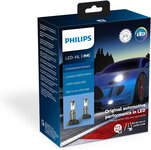
Philips LEDs is a great upgrade. I have these in my old Suburban (9005/9006) housing. Reduced current draw, light aimed at the street with a sharp cutoff line.

81hadaJnWFL._AC_SL1500_.jpg

81+Wf4y7mBL._AC_SL1500_.jpg
 
OP
R

rdoty

ALLIANCE MEMBER
Joined
Feb 7, 2018
Messages
647
Location
Massachusetts
Philips LEDs is a great upgrade. I have these in my old Suburban (9005/9006) housing. Reduced current draw, light aimed at the street with a sharp cutoff line.

81hadaJnWFL._AC_SL1500_.jpg

81+Wf4y7mBL._AC_SL1500_.jpg

Thanks for pointing these out - I wasn't aware of them.

There are a lot of LED replacement bulbs on Amazon and other places that have bad reputations. The general consensus is that they cause a lot of glare when put in standard H4 or H1 housings.

Philips, on the other hand, is a real company that I tend to trust. Unlike many other LED replacement bulbs these are actually certified - in parts of Europe. I can't find anything on US DoT certification for them. Online reviews look good, which is encouraging. The reviews focus on beam pattern and glare and agree that Philips got it right.

Right now for old cars using 5-3/4" or 7" headlights it looks like the choices are:

1. Holley RetroBrite. Complete headlight assembly designed for LEDs. US DoT certification - fully legal. Good reviews. $800 for 4 headlights.

2. Philips Ultinon. H4 and H1 replacement bulbs. Old cars require replacement reflectors/housings like Cibie, Koito, or Hella that use H4 or H1 bulbs. Certification in some European countries. Price around $150 for a pair of bulbs. Bulbs and reflectors around $500 for 4 headlights. Doesn't look like they would fit in my headlight pods.

3. Hella replacement headlights. Sealed beam compatible replacements that use H4 or H1 bulbs (bulbs included). European E-code certification. Price around $200 for 4 headlights.

4. Sealed beam halogen headlights. Full US DoT certification. The standard replacement for the last 30 years. Around $50 for 4 headlights.

5. Cheap aftermarket LED or HID bulbs in a standard housing: Please don't!
 
To avoid these ads, REGISTER NOW!
Top Bottom