To avoid these ads, REGISTER NOW!

Upgrading Old Car Electrical System

To avoid these ads, REGISTER NOW!

Milton Shaw

Well-known member
Joined
Feb 11, 2011
Messages
4,845
One of my roommates in college had a Corvair that aways had starting problems, every time had to roll or push start. As I didn't have a car I helped a lot to get it started. One Christmas the last day before break, his clutch pedal went to the floor. After a months break we got back to school and I tried to get it going. Found a clutch cable and started to put it on. The old one was burned into like you had been welding on it. The ground wire on that one went from battery to frame and then a short link from frame to starter mount bolt. That was intact on the rubber part but the copper inside was not hooked up. Got him a new battery cable, installed it and after a month sitting it started for the first time in about a year. So don't forget the grounds and check to see if it will stretch because its broke inside. This took place back in 1968 so parts for Corvair's were available in parts houses, and we were too broke to pay someone to fix it. Things have changed but I still hate to pay someone to do something I have done before. At 76 years a list of things I can do is getting a lot shorter.
 

Wiz02

Well-known member
Joined
Jul 13, 2007
Messages
2,399
Location
Southeastern PA
I refuse to accept that the list of things I can do is getting shorter! On the other hand, I do accept that it will take me longer to do them. Sometimes much longer...
That's my attitude too, but it's getting harder to maintain.
 

Ohmthis

Well-known member
Joined
Jan 20, 2013
Messages
3,016
Location
Outside of Louisville KY
I refuse to accept that the list of things I can do is getting shorter! On the other hand, I do accept that it will take me longer to do them. Sometimes much longer...
I turn 50 in July. I’m starting to accept that I’m on the downhill slide. I still have this attitude, and hope I will never concede.
 

csp

Well-known member
Joined
Mar 23, 2010
Messages
5,720
Location
Franktown, CO
Even comes with zip ties and dielectric grease. Really nice upgrade kit for basically anything that uses two 7" round headlights, especially for about $20.
They are hard to find $20 these days. The dealerships have largely sold out of their stock nationwide is what I found back in August. None of the Toyota dealerships in my state had them and the kits on eBay were $60-80 or more. I did find one for $16 from a dealership and with standard shipping it was almost $40.
 

WildBill

ALLIANCE MEMBER
Joined
Aug 20, 2021
Messages
2,024
Location
PNW
They are hard to find $20 these days. The dealerships have largely sold out of their stock nationwide is what I found back in August. None of the Toyota dealerships in my state had them and the kits on eBay were $60-80 or more. I did find one for $16 from a dealership and with standard shipping it was almost $40.
The dealer I linked still had a bunch for cheap a couple of weeks ago when I bought four sets
 
OP
R

rdoty

ALLIANCE MEMBER
Joined
Feb 7, 2018
Messages
647
Location
Massachusetts
If anybody is interested in this upgrade kit and having trouble getting them I just got four sets from here, it was only $83 total with shipping for all four sets. I kept ordering them from various dealers and then 2-10 days later the dealer would email me a out of stock notice, these guys shipped the next day. Also as mentioned they have the wrong picture on their site, same as all the dealers I looked at. https://parts.toyotasandiego.com/parts/toyota-headlamp-assembly-8111060p70
Ordered a set using the link WildBill provided. When I went to the site they were $15 with ~$20 shipping. I HATE to pay more for shipping than the product so felt compelled to order two sets... They showed up a few days ago and are as advertised.

$15 is what a set of H4 bulbs will cost at the parts store. The bulbs, relays, connectors and harness are worth well over $15 - so the lamp housings are effectively free!
 
OP
R

rdoty

ALLIANCE MEMBER
Joined
Feb 7, 2018
Messages
647
Location
Massachusetts
I'm re-doing the front door cards on the Imperial. Since this exposes the guts of the door it’s the obvious time to check out the wiring.

There is quite a bit of wiring in the front doors – power windows, power window switch (and connection to the master power window switch in the drivers door), and the infamous courtesy light. Plus the new power and ground wires I added to drive the electric windows reliably.

The wiring harness looked good. It always looks good. If it doesn’t look good I replace it! But there was something strange in the wiring to the power window switch… The wires weren’t exactly what was called out in the Factory Service Manual. Time to remove the tape protecting the harness and see what was going on.

Under the tape was a folded piece of wire not connected to anything else. Just sitting there. Strange! No idea what that was all about. With that wire out of the way the rest of it made more sense.

Anticipating working on the wiring harness inside the door I finally broke down and bought the right tool for the job – Tessa Tape. This tape is made specifically for wrapping wiring harnesses. It is made of cloth to be abrasion resistant. It has a special adhesive that sticks to the tape but not much else – unlike regular electrical tape which leaves sticky adhesive residue all over everything. Tessa Tape is a complement to electrical tape – electrical tape insulates and Tessa Tape is for wrapping wire bundles.

Using the Tessa Tape I re-wrapped the wire bundles I had opened up. I also wrapped the wiring harness where it entered the door to provide additional abrasion resistance and protection for the wires.

While it was on the workbench I took a close look at the socket for the courtesy light. Hmm, it looks like the spring loaded prongs that make electrical contact with the bulb are close to the shell. Wait a minute – what if one of the contacts has worn just enough that it can sometimes make contact with the shell of the socket?

There was the time that touching the socket to the door frame would cause the light to come on. I blamed the LED bulb I was using for the problem – replacing the LED with a regular bulb caused the problem to go away (at that time…). What if the problem wasn’t the LED but instead one of the contacts?

This is simple enough to fix – insulate the shell from any possible way of touching the contacts. A strip of plastic inside the socket would do the trick. I had some mylar drafting film that was perfect for this. Cut a strip just wide enough to barely touch the base of the bulb when the bulb is installed and slip it inside the socket.

I’ve been suspicious for quite a while that there were actually multiple issues with the courtesy lights and that I was seeing different issues at different times. The combination of problems with the door switch and the light socket would seem to cover just about everything I’ve seen. Hopefully the problem is finally fixed!
 

Ohmthis

Well-known member
Joined
Jan 20, 2013
Messages
3,016
Location
Outside of Louisville KY
I don’t think Faraday, Tesla, Edison, or Volta thought that we’d be so damn frustrated with electricity all these years later. I’m enjoying following along. I’m sure I will have issues of my own as I progress.
 
OP
R

rdoty

ALLIANCE MEMBER
Joined
Feb 7, 2018
Messages
647
Location
Massachusetts
I don’t think Faraday, Tesla, Edison, or Volta thought that we’d be so damn frustrated with electricity all these years later. I’m enjoying following along. I’m sure I will have issues of my own as I progress.

I think Edison would understand the frustration. I love his response when a newspaper writer asked him how if felt to fail 1,000 times while trying to invent a useful lightbulb: he replied "I have not failed 1,000 times. I've just found 1,000 approaches that don't work".
 

Ohmthis

Well-known member
Joined
Jan 20, 2013
Messages
3,016
Location
Outside of Louisville KY
I think Edison would understand the frustration. I love his response when a newspaper writer asked him how if felt to fail 1,000 times while trying to invent a useful lightbulb: he replied "I have not failed 1,000 times. I've just found 1,000 approaches that don't work".
I literally thought this about 10 minutes after I posted 😂
 
OP
R

rdoty

ALLIANCE MEMBER
Joined
Feb 7, 2018
Messages
647
Location
Massachusetts
Hopefully this will be the last post on the courtesy light electrical gremlins. It looks like there were two independent – and intermittent! – problems: prongs in the light socket touching the shell and a door switch not long enough to function reliably.

In the last post I described insulating the light socket to prevent potential shorting. A shim on the door provided a temporary fix to the door switch problem.

For a permanent fix I ordered a pair of door switches from Rock Auto. When installing them I replaced the bullet connector on the end of the wire just to be sure. And… The door wouldn’t close. The new door switches were too long. Crud!

When I had described the problem several people here claimed that door switches were adjustable – the shaft could be extended. The Rock Auto switches weren’t adjustable – but the original factory switches were!

Of course the adjustment on the factory switches was frozen. Nothing that a vise, various tools, and strong language couldn’t overcome! With the shaft extended to what looked like a reasonable length there was nothing left but to screw it in place, hook it up, cross my fingers, and close the door.

Success! The switch now works reliably when opening and closing the door!

With two independent problems fixed I hope this problem is fixed for good! Time will tell…
 
To avoid these ads, REGISTER NOW!
OP
R

rdoty

ALLIANCE MEMBER
Joined
Feb 7, 2018
Messages
647
Location
Massachusetts
Great job! I’m learning from your issues. I never knew that the door switches were adjustable.
My issues or the issues I'm having with the Imperial? 😁

Yeah, I didn't know about that until some people mentioned it. This site is a great place to learn. Including learning many new ways to spend money...
 

Ohmthis

Well-known member
Joined
Jan 20, 2013
Messages
3,016
Location
Outside of Louisville KY
My issues or the issues I'm having with the Imperial? 😁

Yeah, I didn't know about that until some people mentioned it. This site is a great place to learn. Including learning many new ways to spend money...
Yeah the issues working on the imperial. I don’t think I can help with your other issues 😂
 
OP
R

rdoty

ALLIANCE MEMBER
Joined
Feb 7, 2018
Messages
647
Location
Massachusetts
I’m moderately proud of figuring out a way to use modern LED technology to replace the 60 year old electroluminescent technology in the HVAC (Heater Ventilation and Air Conditioning) controls. On the other hand, the mounting for the dimmer control for this was not one of my prouder moments…

I had simply zip tied the control module under the dash. In a visible location. Because there wasn’t an hidden place to easily mount it. As I’ve mentioned, for such a large car there is very little space in many areas. Like under the dash.

With the rest of the interior coming together and looking good something had to be done about the HVAC LED dimmer.

When starting the HVAC lighting project I actually ordered two dimmers: a packaged, ready to use unit, and a more compact modular unit that consisted of a 1″x1″ circuit board, connecting cables, and rotary control knob. While I wanted to use the modular unit it was easier to use the packaged unit for prototyping.

The biggest problem, of course, was finding the modular unit. After extensive searching I found it just where it should be – in the box with the rest of the LED components…

You know that old saying if the only tool you have is a hammer, every problem looks like a nail? And my personal favorite: a big enough hammer can drive any screw.

Well, with a 3D printer suddenly any problem looks like something that can be solved with a custom part!

Studying the underside of the dash it looked like the perfect solution would be to extend the custom bracket holding the updated fusebox. I had been wanting to do this anyway – this was the first fusebox bracket I did and the cutout for the fusebox itself had been gouged to “close enough” size with hand tools. Later brackets used laser cut parts from SendCutSend which are a much better fit. And I had an extra blank.

OK, let’s get this party started!

First of all, I wanted the LED to be a bit dimmer than the lowest setting on the dimmer control. I noticed that changing the brightness of the dash lights also dimmed the HVAC LED. Putting on the Electrical Engineer hat that I don’t have, this implies that I can make the dimmer dimmer by adding a resistor to the power supply wire. A 2 ohm or 5 ohm resistor should do the trick. Time to head to Amazon!

Although the LEDs don’t draw much power I was concerned that the widely available (and cheap) 1/2 watt resistors wouldn’t be enough. A bit of searching turned up an assortment pack of 5 watt resistors at a semi-reasonable price.

Without being sure what was needed it made sense to test the resistor circuit before wiring it permanently. Easy enough to do – grab a couple of jumper wires with alligator clips. One wire from power to resistor and the second from resistor to dimmer. Hook it up, wait for night, turn off the workshop lights, wait for darkness, and verify that I had the correct value.

Hmm, not much difference in brightness with the 2.2 ohm… OK, the next size up is 3.3 ohms Still not enough change. Well this is why I got the assortment pack! Grab the 10 ohm. Better, but still not quite what I wanted. 22 ohm? 47 ohm? Finally at 100 ohm it was close to the (lack of) brightness I was looking for.

This was much more resistance than I expected – glad I experimented first! Discussing this later with a friend who is a real electrical engineer, he told me that he sometimes has to go as high as 500,000 ohms in similar circuits. Huh, learn something new every day! Guess I should have tried 1,000 ohm and 10,000 ohm resistors while I was at it.

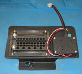
Now to design the case to hold all of the electrical components. Complex designs are basically a bunch of simple designs connected together. In this case I needed a mount for the circuit board, a holder for the resistor, a baseplate for these, a top plate to provide protection, and four columns to tie everything together.

And that is exactly how I designed it: a mounting plate for the circuit board that picked up the screw holes in the circuit board and was extruded to provide space for the components sticking out of the circuit board. A pair of rectangular pillars with holes for the tubular resistor. These were split in half forming a saddle so that the resistor could be inserted and then firmly clamped in place. Next was the baseplate with both of the mounts integrated into it and round columns at each corner. Finally, a top plate that screwed to the columns and which included the top half of the resistor mount.

Print it out, test fit everything together…. And as usual discover a few things that needed to be tweaked. Absolutely normal. The amazing thing about CAD and 3D printing is that you can do this quickly, easily, and cheaply. For example, these parts used about $0.25 of material.

HVACDimmerHousing.JPG
Dimmer Module Box

To be continued...
 

stinkity stoink

Well-known member
Joined
Apr 8, 2007
Messages
735
Location
New Jersey
um…..quick and easy is not the way for me with cad.
Design that small box…. 2 to 3 hours.
print it and realize you need a few adjustments. Head back to the design and realize you don’t know how to open it again and spend 45 minutes in utter frustration trying to figure it out watching you tube.
Keep the updates coming.. love the electrical write ups
 

Sbusmech

Well-known member
Joined
Apr 7, 2024
Messages
265
Location
Texas
Look up Painless. They'll probably have something you are looking for. I agree, electrical and fuel lines should be not only checked but replaced to reduce headache/heartache later on vehicles a half a century old.
 
OP
R

rdoty

ALLIANCE MEMBER
Joined
Feb 7, 2018
Messages
647
Location
Massachusetts
um…..quick and easy is not the way for me with cad.
Design that small box…. 2 to 3 hours.
print it and realize you need a few adjustments. Head back to the design and realize you don’t know how to open it again and spend 45 minutes in utter frustration trying to figure it out watching you tube.
Keep the updates coming.. love the electrical write ups
Stinkity, you are absolutely right!

Frustration with CAD is a normal part of the learning curve. When I first started using Fusion a couple of years ago it was nothing but pounding my head against the wall - exactly as expected. Since I got the 3D printer I've been using it for more projects - and many more iterations per project - and it has gotten steadily easier. Again, exactly as expected. Mastering a skill is almost entirely a function of time spent practicing that skill.

One of the things I love about having a 3D printer is that it makes iteration SO much easier!

Expertise is something you end up with, not something you start with.
 
OP
R

rdoty

ALLIANCE MEMBER
Joined
Feb 7, 2018
Messages
647
Location
Massachusetts
With the housing done, turn to the bracket. Remove the original bracket from under the dash and use it as a reference. Decide how much it needs to be extended to support the dimmer box and dimmer knob. Mark this extension as well as the bends for bolting the bracket to the dash on the fuse box bracket panel.

Drilling the mounting holes for the dimmer box was easy – take the top plate and use a transfer punch to mark the center of each mounting hole and then drill them. Determine where the control knob should go and drill a hole for it. Drill a hole for the mounting bolt that will secure the bracket to the bottom of the dash.

Bend the bracket so it will mount properly and weld a nut to it. With an earlier version of the bracket I used a separate nut – trying to hold the bracket and loose nut in position while starting a bolt proved to be a nightmare... Just secure the nut in the first place! Test fit the bracket. It fits, so hit it with a couple of coats of paint.

Really should clean up the dimmer box before final mounting. There are four wires on the dimmer – two for power in and two going to the LEDs. Add these wires, sleeve them, and add a connector to the end. Add a matching connector to the wires in the dash. This will simplify installation and any future maintenance on the dimmer circuit.

OK, to be perfectly honest, I’m turning into a bit of an electrical snob as I learn more about wiring.

HVACDimmerHousingFinal.JPG
Dimmer Module ready to install

Bolt the dimmer box to the bracket, mount the control knob in its hole, and we’re finally ready for installation. I had an extra fusebox from another project, so I temporarily mounted it in the bracket to make sure everything fit.

HVACDimmerHousingInstalled.JPG
Dimmer Module mounted on bracket with reference fusebox

Moment of truth time: slip the bracket under the dash, position the fusebox in its cutout, and bolt the assembly to the dash. With the mounting bolt secure, run in the four machine screws that secure the fusebox to the bracket. Plug in the connector for the dimmer module.

Fortunately it was late enough that it was dark. Turn off the workshop lights, turn on the Imperial headlights, and adjust the dimmer knob. Everything worked!

And there was much rejoicing!

The dimmer module is now securely mounted, completely hidden under the dash, yet the control knob can be easily reached to adjust brightness. I’m declaring this a success and moving on to the next project.
 
OP
R

rdoty

ALLIANCE MEMBER
Joined
Feb 7, 2018
Messages
647
Location
Massachusetts
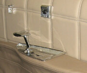
The power window switches on old Chryslers have a fatal weakness – the spring clips that hold them in place break easily.

The window switches are inserted into the door cards. Every time the door card is removed the switch must first be removed – the wires aren’t long enough to allow the door card to be removed with the switch in place.

PowerWindowSwitch.jpg
Power Window Switch

The switch is held in place by four steel clips. The design of the clips should be fine – this same design is used in many places with good results. Unfortunately, the Chrysler clips seem to be made of mild steel rather than the expected spring steel. After a few cycles they lose their grip. When you attempt to bend them back to their original shape they break. Most of the time it doesn’t matter – few cars have the door cards removed even once. On a restoration like this, on the other hand, you will start breaking the clips.

Well, not a major disaster! If one breaks you still have three left – works fine. Ummm, OK, after two break you still have two. Make sure they are on opposite sides of the switch and it still works. Yeah, one clip doesn’t hold the switch in place at all.

These switches are hard to find. The clips are complete unobtanium.

You saw this coming: the last time I had this door apart I broke the third clip. Yup, I’m totally up the excrement waterway without a manual propulsion device.

Extensive cogitation didn’t uncover a way to make new steel clips. However… What about 3D printing a switch retainer? Didn’t see that one coming, did you??

The problem is that the hole the switch fits into is a really tight fit. I couldn’t come up with a design that would hold the switch, fit into the hole, and include a retention mechanism.

If only you could 3D print rubber. It looks like it should be possible to design a sleeve for the switch with a couple of bumps that would squish when inserting and hold the switch in place.

You can’t print with rubber, but you can get TPU filament. TPU, or Thermoplastic PolyUrethane, is a flexible material with many of the characteristics of rubber. Time to order a roll of TPU and fire up the design system!

The concept was a sleeve that would go over the switch with bumps on the inside fitting into grooves in the switch body and bumps on the outside to hold it against the edges of the hole it fits in.

As mentioned the hole is a tight fit. OK, do a preliminary design with 0.010″ thick walls and run a test print. Resulting in complete failure – walls completely too thin for the printer. What about 0.020″? It is a bit too large, but maybe the TPU is squishy enough to be forced through the hole? This part printed successfully, so work on a “final” design and load up the TPU filament.

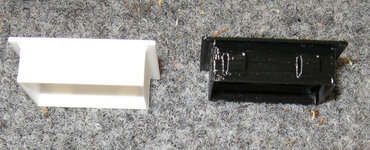
PowerWindowSwitchSleeve.jpg
Left: prototype in PLA. Right: final part in TPU

With the TPU part in hand give it a close inspection. The part is firm but flexible and seems to be pretty tough – TPU lives up to its billing.

First question: can I install it on the switch? And will it stay in place?

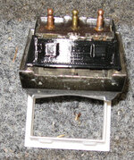
PowerWindowSwitchWithSleeve.jpg
Switch with sleeve

Yes – it fits snugly over the switch and locks securely in place. OK, easy part done. The big question: will it fit into the hole?

Nope. Side to side seems like it could go, but top to bottom is just too tight – won’t go without peeling off the sleeve. Krud! So close, so close…

If it won’t go in top to bottom, what happens if I cut off the face on the top? Is the remaining part rugged enough to hold together when being stuffed into the hole, or would it just fold back?

Turns out that you can now slip the switch with sleeve into the hole, right up to the point where it hits the retaining bumps. Cross fingers and discover that you can’t apply any pressure with crossed fingers. Uncross fingers and wiggle and stuff the switch into the hole…

It goes in! It doesn’t come back out! And there was much rejoicing!

Once again modern technology comes to the rescue. Leaving only one question: what can I 3D print next?!?
 

Ohmthis

Well-known member
Joined
Jan 20, 2013
Messages
3,016
Location
Outside of Louisville KY
Oh my! “Yup, I’m totally up the excrement waterway without a manual propulsion device.” And “Cross fingers and discover that you can’t apply any pressure with crossed fingers. Uncross fingers and wiggle and stuff the switch into the hole…”, Rdoty you are cracking me up!!! That’s a great solution! I keep saying I need a 3D printer hmmmm!
 
OP
R

rdoty

ALLIANCE MEMBER
Joined
Feb 7, 2018
Messages
647
Location
Massachusetts
Oh my! “Yup, I’m totally up the excrement waterway without a manual propulsion device.” And “Cross fingers and discover that you can’t apply any pressure with crossed fingers. Uncross fingers and wiggle and stuff the switch into the hole…”, Rdoty you are cracking me up!!! That’s a great solution! I keep saying I need a 3D printer hmmmm!
Come over to the Dark Side, we have cookies! Yes, Dark Side is partially a comment on my electrical skills...

The real power comes when you combine 3D printing with Computer Aided Design, some problems to be solved, and a pinch of insanity. It is ridiculous what you can with today's technology. If you have a decent PC for CAD, amazingly good 3D printers are available starting around $300.

I'm currently working on organizing parts of the shop using the GridFinity system of customizable printed "bins" (they are a bit more than what "bin" implies) and baseplates - an incredibly deep and wide rabbit hole that you kind of just slip down. I'm thinking about starting a thread on that, both to amuse people and to get others to share what they are doing.
 

Ohmthis

Well-known member
Joined
Jan 20, 2013
Messages
3,016
Location
Outside of Louisville KY
Come over to the Dark Side, we have cookies! Yes, Dark Side is partially a comment on my electrical skills...

The real power comes when you combine 3D printing with Computer Aided Design, some problems to be solved, and a pinch of insanity. It is ridiculous what you can with today's technology. If you have a decent PC for CAD, amazingly good 3D printers are available starting around $300.

I'm currently working on organizing parts of the shop using the GridFinity system of customizable printed "bins" (they are a bit more than what "bin" implies) and baseplates - an incredibly deep and wide rabbit hole that you kind of just slip down. I'm thinking about starting a thread on that, both to amuse people and to get others to share what they are doing.
Please do start a post. There are a few 3d printer threads on here. My brother got one and is starting down that rabbit hole. I see a lot of potential with them. My only concern is how steep the learning curve is it a drawing program and the 3d printer. I don’t have a great deal of extra time, hence why it’s taking so long with my old truck.
 
OP
R

rdoty

ALLIANCE MEMBER
Joined
Feb 7, 2018
Messages
647
Location
Massachusetts
Plans for a future radio upgrade included adding a pair of speakers to the package shelf behind the rear seat. Time to actually install them while the interior was apart.

Turns out that there were already cutouts in the package shelf for standard 6×9 speakers – all that was required was to drill a couple of mounting holes slightly larger for all the screws to line up. One of the few cases where new parts fit easily into this old car!

After installing the first speaker I discovered that the center cone was sticking up just a bit too far. No problem – the speakers come with a cover. Except that I despise the look of aftermarket speaker covers under the rear window! To me it looks like someone took the easy way out on a speaker install. Bad enough on a muscle car and completely out of place on a luxury car.

No big deal. Just make a spacer for the speakers – I’ve done this before. A chunk of 1/4″ plywood, some quick surgery with a jigsaw, and the speakers are spaced.

As usual, the speaker instructions included a template for cutting mounting holes and making spacers. You can guess what happened as I got ready to start slicing up some plywood – you know, a 3D printed part would look cleaner…

To make matters worse, I’ve been taking a online course on Learn Autodesk Fusion 360 in 30 days. Lesson 2 covered how to trace a picture of a part to make a 3D model. I’m clearly required to apply my newly gained knowledge!

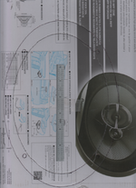
In addition to lines, circles, surfaces and solids, Fusion includes an entity type called Canvas that holds a picture. One of the features of a Canvas is that you can select 2 points on it and scale the picture to a known size. Scale the picture to full size and you can accurately trace around it.

With these speakers the template is on the back of the box. Known distance, known distance… Hey, if you include a steel machinists rule in the picture you will have a really accurate known distance!

SpeakerSpacerTemplate.png
Template for speaker spacer

Open a new Fusion design and create a Canvas from this picture. Click on the two ends of the machinists rule and specify that these are 6″ apart. Considering the accuracy of the rule and the precision you can achieve selecting the sharp end of the rule this Canvas should be accurate to within 0.010″ – plenty for this case. Using the usual trace and cut approach I would have trouble doing much better than 1/16″.
Now, how to trace this part? It looks a lot like an ellipse – maybe it actually is? One way to find out!

An ellipse is defined by three points: center, long axis, and short axis. If long axis and short axis are the same length you have a circle.
Unfortunately the template didn’t mark the center point. But the four mounting holes look like they are evenly spaced… Create a 1/4″ circle and precisely position it over the mounting holes. Once you zoom in you can do this very accurately.

Diagonally connect the circles with two construction lines. Where these lines cross is the center of the ellipse.
Bring up the ellipse tool, select the center, select the long axis, and drag the ellipse to the short axis.

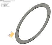
Huh! Look at that – the ellipse perfectly overlays the template! No need to worry about using line segments, circles, splines, or any other complications. Create the outer ellipse the same way and done. The design process took about 5 minutes – and 3 minutes of that was looking up how to create a Canvas!

Extrude the design 1/8″ to create a solid and send it to the 3D printer. 45 minutes later grab the part off of the printer and use it to mount the speaker. Fits perfectly!

SpeakerSpacer.png

Print out another spacer, mount the second speaker, connect the wiring, and this task is done.

This job was so simple I almost didn’t write about it. But the approach of designing by tracing around pictures is so powerful I had to share it. I expect to use this more in the future!

I have to do a plug here for the YouTube channel Product Design Online. I’ve reached the point with Fusion where I’m comfortable with the basics and ready to learn more. To my surprise I started learning new things I could use in the very first lesson – and continue to learn more in each following lesson! Highly recommended.
 

stinkity stoink

Well-known member
Joined
Apr 8, 2007
Messages
735
Location
New Jersey
Fantastic job!! I have been going back and forth with the same class. Unfortunately I have been stuck on lesson 3 or 4 and that was several months back. I am so interested in learning it , but I have such a bad tendency of being distracted. Hopefully this gets me motivated.
 
OP
R

rdoty

ALLIANCE MEMBER
Joined
Feb 7, 2018
Messages
647
Location
Massachusetts
Fantastic job!! I have been going back and forth with the same class. Unfortunately I have been stuck on lesson 3 or 4 and that was several months back. I am so interested in learning it , but I have such a bad tendency of being distracted. Hopefully this gets me motivated.
Stinkity,

Do you have some parts you need to design? My personal experience is that trying to learn a skill, like welding, machining, sewing, or 3D design is difficult unless I have something specific I'm trying to build or a specific problem I'm trying to solve. Then I flip over into "how do I solve this problem?" mode and get much more focused. For me it makes things much more concrete.

I think I've mentioned that I put off getting a 3D printer for about 5 years until I had a project that required that capability.

With these Fusion lessons I've been taking what I can use from them. I don't think I will ever make a bottle, but the part of the lesson on creating splines will be useful to me.

So, my suggestion is find a real problem you need to solve. Even if you have to create one!
 
To avoid these ads, REGISTER NOW!
Top Bottom