To avoid these ads, REGISTER NOW!

Upgrading Old Car Electrical System

rdoty

ALLIANCE MEMBER
Joined
Feb 7, 2018
Messages
647
Location
Massachusetts
I’m restoring an old car – a 1963 Imperial. Yes, I’ve had my head examined. I have one.

One of the biggest weaknesses in older cars is the electrical system. These were typically marginal from the factory and don’t age well. Marginal size of wire, corrosion in connectors, switches, and wire, as well as 50 year old insulation all combine into a lurking dragon waiting to pounce at the worst possible time.

It is easy to find horror stories about melted connectors, burnt wiring, dash fires, and engine fires in old cars. Plus the reliability problems of things simply not working or not working well.

In addition to the steady weakening of the electrical system as it ages, demand for power increases. Traditional headlights have been replaced with high power quartz headlights. Radios have been replaced with infotainment systems – a modern infotainment system with a big amp can require more power than the entire car did in 1963! In addition there are more electrical devices in use today than 50 years ago.

I’ve really gotten used to the headlights in modern cars. I’m reaching the point of “enhanced maturity” where I don’t see as well at night as I used to, and powerful headlights are more a necessity than a luxury. The original headlights in the Imperial looked like they were using actual candles!

The Imperial came with a 35 amp alternator; air conditioned cars like mine were upgraded at the factory to a “high capacity” 40 amp alternator. In comparison, modern cars typically have 100+ amp alternators with many exceeding 200 amps.

Fortunately something can be done about this!

I’m using two main references: first is a set of tutorials on the Bodenzord website going into great detail on how to build a modern wiring system. These tutorials are superb and have cost me a lot of money in parts and tools.

The second is Daniel Stern Lighting which provides a lot of insight into upgrading lighting systems. This site is complementary to the Bodenzord site and makes clear the importance of wire size, relays, grounding, and headlight and bulb selection.

These two sites educated and inspired me to plan significant upgrades to the Imperial wiring, including:
  • Think about and design a set of modifications and improvements to the electrical system.
  • Upgrade the factory under-dash fuseblock to a modern fuseblock. The original fuseblock contained six glass fuses. The new fuseblock has 20 ATC Mini fuses on two separate buses – 10 switched/accessory and 10 unswitched/always on. Each bus is driven with 40 amps of power through new wiring.
  • Bypass the ammeter. This is perhaps the greatest weakness of old Mopars – the entire electrical load is routed through a gauge in the instrument cluster. I’m bypassing the ammeter and routing most loads through new wiring. The only downside is that the ammeter no longer shows charging status. I will be adding a voltage meter as part of the upgrades – voltage meters are actually more useful in determining what is going on with the electrics.
  • Changing how power is delivered from the alternator and battery to the rest of the electrical system.
  • Upgrading the firewall bulkhead connector to a modern waterproof design.
  • Adding a new under-hood fuse and relay block.
  • Moving heavy loads like headlights from the factory wiring to new wiring.
  • Moving all heavy loads from switches to switch/relay configurations.
  • Installing new upgraded wiring for major circuits – typically one to two sizes heavier wire for each circuit.
  • Redesigning the alternator circuit with larger 60 amp alternator, heavier wiring (go from 12ga to 6ga), and a solid state voltage regulator.
  • Upgrading the grounding system. Many electrical problems, especially in older cars, are due to poor grounds. The grounds are just as important as power!
  • Labeling everything to simplify troubleshooting and to help me when I have to work on something in a couple of years.
This is just an introduction to the project - I will be posting updates on the actual work in the coming weeks.
 
To avoid these ads, REGISTER NOW!

Jakemedic

Well-known member
Joined
Jul 26, 2013
Messages
722
Location
Cornfields of SE Iowa
There is a company out there that makes custom wiring harnesses for old vehicles. I just can’t think of their name. I purchased one when I was into old flat nosed Chevy vans from the 60’s. They were am because of the color code and what the wires were for printed every 6” or so. All connected to a new fuse panel. Made it easy to simply rewire and replace the entire electric system.

I looked around and couldn’t find the info, but these folks seem to do the same thing. https://streetrodelectrics.com/?msc...m=+special +wire +harness&utm_content=special

good luck!
 

Walkers

Well-known member
Joined
May 17, 2021
Messages
3,912
Location
Cave Creek Az
I have to admit that current wiring kits are very nice, easy to use, and have a lot of great features for a very reasonable price.
 

Ricky Joe

Well-known member
Joined
Sep 15, 2013
Messages
2,452
Location
Roanoke, Va.
I probably have the factory service manual for that car. If you want, I can check and see. I know I’ve got some from the 1960s, just not sure if I have 1963. The Imperial had its own separate set of manuals. Good to upgrade. I am a bit surprised that you are putting heavier wire. That would usually be something that a six volt system would need. I’ve never upgraded a twelve volt, so I’ll trust you on that one.
 

kerrynzl

Well-known member
Joined
Nov 8, 2013
Messages
5,054
Location
Tauranga, New Zealand
Ground EVERYTHING with star washers is a good start

AND
A diode shunt for the ammeter if you want to keep the instrument panel stock [and everything still working]
If the stock Chrysler ammeter is capable of handling 40a this would read accurately until it is exceeded [then the shunt opens and bypasses the excess]

Old car wiring is dirt simple to repair/rewire [I did this on my 57 Chevy]
 
OP
R

rdoty

ALLIANCE MEMBER
Joined
Feb 7, 2018
Messages
647
Location
Massachusetts
Ricky Joe: Thanks for the offer - I have the factory service manual and it is invaluable. I will be describing how I labeled all of the wires with both circuit number from the factory wiring diagram and with function. Some of the heavier wires are probably not really required, but key circuits like headlights and power windows are simply too small from the factory. And 4ga wire is just not enough to start a big block!

kerrynzl: completely agree on grounding - I will be talking about that a lot. I don't know if old car wiring is "dirt simple", but it is fairly straightforward if you have the documentation, take your time, and think a little.

Others: Good references for the wiring kits. In many cases these are the way to go. Because of the small numbers of Imperials made - around 5,000 a year - there isn't a lot of aftermarket support. Also, I'm just replacing under hood wiring, not the much more complex under dash wiring.
 

larry4406

Well-known member
Joined
Jan 27, 2006
Messages
19,462
Location
Northern Virginia
On the Mopar forums (Moparts.com, etc) there is a guy who goes by the the name crackback and he builds plug and play harnesses with relays for the head lamps to improve their performance and lessen the strain on the OEM harness.

I believe this is his contact information
Rob Yule
robule1 at yahoo.com

I only surf the E-body forums (1970-74) so not sure if his products can help you but his expertise sounds like it can.
 

Monza Harry

Well-known member
Joined
Dec 29, 2018
Messages
1,433
Location
Windsor ON
Daniel Stern Lighting was actually better back about 10 years ago, unless I missed the previously included information on how our eyes see different colours, he see's [pun intended] no use for those gimmicky blue headlights that were the rage awhile back and I agree from my personal experience. You seem to have a good plan and are getting top shelf feedback here. Please keep us updated. Harry
 

Big Bad Dad

Well-known member
Joined
Jan 31, 2010
Messages
2,664
Location
Southwest/ Central Va.
I am a member on a Mopar website/forum "For B Bodies Only". It has a lot of info. Parts and cars for sale too. Also has a sister site "For C bodies Only". I think Imperials are included on there. Might want to find it and join. (If you haven't already.)
 

theoldwizard1

Well-known member
Joined
Feb 22, 2011
Messages
43,227
Location
SE MI
One of the biggest weaknesses in older cars is the electrical system. These were typically marginal from the factory and don’t age well. Marginal size of wire, corrosion in connectors, switches, and wire, as well as 50 year old insulation ...
Actually, wire harnesses on older car were not that bad ! The wire gauge and insulation had to hold something like 20 lbs ! Yes, a vehicle that old might have a lot of brittle/cracked insulation.

Harnesses were wrapped with "harness tape", 3/4" PVC electrical tape with NO ADHESIVE ! It is reusable. Joints inside of a harness were 1"+ bared wire twisted together at least 2 turns. The joint and typically the harness tape ends were wrapped with "friction tape", a cloth tape, impregnated with a non drying adhesive.

This may sound crude, but it was very effective ! Even modern wire insulation will turn brittle in 50+ years of hot and cold cycles.
 
OP
R

rdoty

ALLIANCE MEMBER
Joined
Feb 7, 2018
Messages
647
Location
Massachusetts
The first post introduced our strategy for upgrading the electrical system. Time to get to work implementing that strategy!

As Captain Obvious has observed, electrical systems consist of two parts: power and ground. While power is obvious (pun intended), ground is often an afterthought. This makes the ground system a logical place to start for building a reliable electrical system.

The challenge with ground is that it uses the body and frame to provide an electrical path, often with poor connections. These connections are barely adequate when new and degrade over time. The battery ground is connected to the engine block, providing high current power to the starter. The engine block is then connected to the firewall with a single ground wire and a small screw. Various electrical components around the car are then grounded to the body.

Several months ago, as part of general preparation, I welded two bolts to the frame – one near the firewall ground point and one near the battery. This provides solid electrical connections to the frame with no chance of corrosion, making a high quality ground available to the entire car.

I then had two heavy duty ground wires custom made by GenuinedealZ. These ground wires were made from 4 gauge (4ga) tin-plated solid copper wire with heavy duty terminals and adhesive lined heat shrink tubing. What does all this mean?

Solid copper wire is a better conductor and stronger than aluminum or copper coated aluminum (CCA) wire. Low cost wiring is often CCA, which doesn’t hold up under severe service. Since copper wire by itself can corrode, a tin coating is used where it is likely to get wet. Tin coated wire is often called marine grade as it holds up to the harsh conditions encountered in marine use. Areas of a car that are exposed to moisture, such as under hood use, are good places to use marine grade wire.

Factory ground wires are often 12ga or perhaps 10ga if you are lucky, which was adequate in the 1960’s. As a point of comparison, 4ga wire was often used for the high current starter. When ordering these custom cables the cost difference between 8ga and 4ga is less than $1.00 per foot and these cables are only one or two feet long, so it makes sense to upgrade.

Heavy duty terminals, also made of tin coated copper, are sized for their application. In this case I have 1/4″ bolts for the frame ground and firewall ground and 3/8″ bolts for connecting to the engine block. One cable goes from the frame ground to the firewall bolt and the other goes from the firewall bolt to the engine block.

Sealing electrical components from moisture is a key to long life. Heat shrink tubing provides mechanical and electrical connection. Adhesive lined heat shrink tubing has a heat sensitive glue on the inside. When heated this adhesive melts and forms a waterproof bond. Adhesive lined heat shrink tubing is the standard for marine applications and is great for automotive applications.

The screw connecting the original ground wire to the firewall has been replaced by a 1/4″ bolt through the firewall. The firewall was sanded clean around the bolt hole for a good electrical connection, then the bolt was run through the two new grounding wires. After this the area around the bolt was sealed. Inside the car a 10ga grounding wire was attached to the bolt – this wire will be attached to a grounding block under the dash.

A dedicated ground line was run from the negative terminal of the battery to the other grounding bolt on the frame. This is currently a 10ga wire – it will be upgraded to a 4ga wire the next time I order custom cables. This grounding point will also be used by the power distribution box planned for high current loads like headlights.

The net result of all of this is a very solid ground system to support the rest of the electrical system. The existing body ground has been improved, which will help in general. Solid electrical connections of the body to the frame, engine block, and battery negative terminal will eliminate many potential problems. Using grounding blocks and dedicated ground wires for high current use cases will further improve electrical performance.

While not as exciting as other work, starting with the grounding system is key to electrical success.
 

Monza Harry

Well-known member
Joined
Dec 29, 2018
Messages
1,433
Location
Windsor ON
As you stated in post 15 those are stellar upgrades and will addresses many (dare I say most?) electrical issues. We see auto electrical systems very similarly! Still following along! Thanx for sharing. Harry
 

Ohmthis

Well-known member
Joined
Jan 20, 2013
Messages
3,016
Location
Outside of Louisville KY
Great start on your project. My only words of caution are to keep the factory engineering in place on the grounds. Larger bonding jumpers are fine. What may be a problem is replacing the frame or body (the original ground) with a wire. Electricity flows on the path of least resistance. If by chance there is an issue with one of your grounds, electricity will find the next least restrictive path. That may be through a wire too small for the load. If the factory path is ground from battery to block, to frame, to body then keep the original path. From what I am reading you have multiple grounds off of the battery. One to the block, one to the frame, and one to the body, maybe even another to a ground block under the dash. Let’s say that there is corrosion on your ground to block. There is a smaller wire that is attached to the block and is bonded to the ground block as part of the engine harness. Now the starter will find that path through the smaller wire to the ground block, to the battery through another smaller wire. The wire will be pushed way past it’s current carrying capacity. I hope this helps out.
 
OP
R

rdoty

ALLIANCE MEMBER
Joined
Feb 7, 2018
Messages
647
Location
Massachusetts
Excellent points! The new frame and body grounds are 4 ga, which is what the original starter cables were. From the battery negative terminal are: (1) 1/0 ga to block. (2) 4 ga to frame bolt. (3) 6 ga to underhood fuse/relay box where it provides ground for headlights and other accessories.

The back of the block has two ground cables attached: (1) 4 ga to second frame bolt. (2) 4 ga to original body ground point.

Starter cable and battery to block cable have been upgraded to 1/0 ga. There shouldn't be any problems with undersized ground connections. More details coming!
 

Ohmthis

Well-known member
Joined
Jan 20, 2013
Messages
3,016
Location
Outside of Louisville KY
Excellent points! The new frame and body grounds are 4 ga, which is what the original starter cables were. From the battery negative terminal are: (1) 1/0 ga to block. (2) 4 ga to frame bolt. (3) 6 ga to underhood fuse/relay box where it provides ground for headlights and other accessories.

The back of the block has two ground cables attached: (1) 4 ga to second frame bolt. (2) 4 ga to original body ground point.

Starter cable and battery to block cable have been upgraded to 1/0 ga. There shouldn't be any problems with undersized ground connections. More details coming!
The size(s) aren’t an issue. It’s the multiple paths. When you loose one point the other(s) have to support the load. Ideally you want a single path for the current to flow. The reasoning is that if you loose the path, things stop working and a repair can be made. In your case, a separate path can be used and a wire can be overloaded. I’ve seen this issue, and have repaired the results. I hope I don’t sound harsh. We all want our projects to be successful and last a long time.
 
OP
R

rdoty

ALLIANCE MEMBER
Joined
Feb 7, 2018
Messages
647
Location
Massachusetts
Ohmthis - not harsh at all, thanks for your feedback! I started this thread to share what I've learned and to learn more from people like you. In many cases there are multiple ways to do things as well as trade-offs in the various choices.

I tend to like redundancy. You raise good points about issues that can arise from redundancy - these should certainly be considered. And mitigated.

A big part of the mitigation strategy here is corrosion prevention. All of the high current cables are marine grade tin plated wire with good tin plated connectors and adhesive filled shrink wrap on all connections. All other underhood wiring is GXL wire with waterproof connectors. Another part of the strategy is to ensure that the redundant paths can carry the full load, which I believe is the case here.
 
To avoid these ads, REGISTER NOW!

no704

Well-known member
Joined
Apr 27, 2016
Messages
5,225
A coworker installed a winch on his new FJ. Relay pack shorted out. Ground path was thru the brake lines. Dealer actually repaired it under warranty!
 
OP
R

rdoty

ALLIANCE MEMBER
Joined
Feb 7, 2018
Messages
647
Location
Massachusetts
One of the greatest weaknesses in the electrical system of older cars is the bulkhead connector that connects the engine compartment to the rest of the car. Unlike modern bulkhead connectors, these old connectors were not sealed – this leads to corrosion in the connector which increases resistance, reduces voltage, and leads to a wide range of problems.

The problem is made even worse by undersized wiring which is also corroding and likely to have cracking insulation.

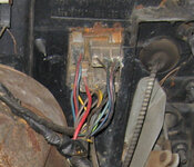
Bulkhead Connector.jpg
Bulkhead Connector 1963 Imperial

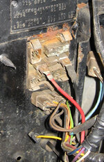
Bulkhead No Connector.jpg
Bulkhead connector with plugs removed

In this second picture you can see the corrosion inside the bulkhead connector. Surprisingly the wiring insulation is still in good shape. The red and black wires are power and ground and are 12ga – this is marginal for today’s electrical loads.

Modern cars use waterproof sealed electrical connections. Examples of this include Weather-Pack, Metri-Pack, and Deutsch. I decided to use Metri-Pack and Weather-Pack which are widely available and “reasonable” cost.

Weather-Pack connectors are rated at 20 amps. Different models of Metri-Pack are rated at 14 to 60 amps per connector; I’m using the Metri-Pack 280 family, which is rated at 30 amps per connector. Unfortunately Metri-Pack is not available in high pin count bulkhead connectors.

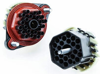
The best choice is the Weather-Pack 22 Position Bulkhead Connector. This is a sealed bulkhead connector that supports 22 connections. Using an adapter plate it fits into the same space as the factory bulkhead connector, meaning that it isn’t necessary to cut the firewall.

WeatherPack 22 position bulkhead connector.jpg

As mentioned, the Weather-Pack connections are only good for 20 amps. I really need more power than this. The factory bulkhead connector only has 18 connections – this means 4 connections are available for other use.

I will be using two of these to provide switched power and two to provide unswitched power. Combined with the factory circuits (one for switched and one for unswitched) this will give me three 20 amp circuits – which provides 60 amps total power delivery – for both switched and unswitched power.

Installing the Weather-Pack bulkhead connector was a tedious process. For each wire:
  • Identify wire and circuit. Cross check terminal location and wire color against factory service manual.
  • Double check identity of wire and circuit.
  • Create 2 labels for wire. This identifies the circuit and use.
  • Cut wire from the old bulkhead connector.
  • Slip label over wire.
  • Slip Weather-Pack seal over wire.
  • Strip end of wire.
  • Crimp Weather-Pack terminal onto wire.
  • Use heat gun to shrink the label.
  • Move on to next wire
At the end of this process you have 44 wires ready to plug into the connector shells. It is critical to get the same wire plugged into both sides of the connector – crossing wires is a bad thing. To make it more entertaining the two halves of the connector are done separately and are mirror images of each other.

The way to avoid problems is to have a map of the connectors showing where each wire goes. A spreadsheet is a surprisingly good tool for this.

Start by listing all of the circuits on the factory bulkhead connector. Include connector pin location, circuit number, wire color, and wire size. Also include a description of the circuit. Looking forward, plan which pin location on the Weather-Pack connector will be used.

Factory Bulkhead Wiring.jpg

Spreadsheets are square and the Weather-Pack bulkhead connector is round. The answer is to visually map spreadsheet cells to the round bulkhead. In fact, do this twice – once for both male and female connectors.

WeatherPack Pin Map.jpg

This map shows the location of each pin and the identity of each pin – each pin is identified by a letter which is the same on both the male and female connectors. Each wire is labled with the circuit number and description.

The process is to start at the bottom of the connector, find the wire that goes in that location, and insert it into the connector until it locks into place. Then find the next wire and insert it. Double check to ensure that you have the right wire and the right pin location. Continue this process until you have plugged in all of the wires.

After completing the first connector do the same thing on the other connector – making sure you are using the correct diagram, male or female!

At the end of this process you will have a new sealed bulkhead connector installed in the firewall with all circuits labeled.

weatherpack-bulkhead-installed.jpg
 
Last edited:

whitesco

Well-known member
Joined
Aug 1, 2022
Messages
399
Location
Pittsburgh, PA (ish)
If it was mentioned before I missed it, but Painless does a lot from whole vehicle harnesses to custom stuff for hot rods:
 

MBfreak

MEMBER EMERITUS
Joined
Dec 10, 2010
Messages
2,301
Location
Linkoping , Sweden
Buy a 90s MB and have fun. Insulation goes brittle, so brittla as to shear the multistranded wires inside
A friend´s 420 SE had to have the entire engine bay harness replaced. $ 1600 just for the loom.

That is progress. Stuttgart style.

Ola
 

MBfreak

MEMBER EMERITUS
Joined
Dec 10, 2010
Messages
2,301
Location
Linkoping , Sweden
Another oldie but goldie is the W110/1/3 from the sixties. Solid, hiq PVC wires, wonderful, silver plated plug in contacts.
All joints soldered.
And to really go overboard MB used an early type silicon-insulated wire from the key switch to energize the solenoid.
After 50 years everything loooks like new.
EXCEPT that silicon insulated 2,5 sqmm wire to the starter solenoid. The silicon has turned into dust but since wire is running with many others in a well made insulating pipe, nothing happens. Until the last 20 cm where it is free and shorts out, creates a holy mess of the loom due to overheating.

Ola
 

RPH

Well-known member
Joined
Dec 17, 2006
Messages
4,190
Location
Michigan Thumb
Just keep track of your wires. Extras are appreciated but only a few needed. One wonders how Ford came down with this problem on wiring.
"We didn't know that our wiring harness for Mach-E was 1.6 kilometers longer than it needed to be. We didn't know it's 70 pounds heavier and that that's [cost an extra] $300 a battery," he said on a call with investors Thursday. "We didn't know that we underinvested in braking technology to save on the battery size."
 

F-22

Well-known member
Joined
Jan 23, 2022
Messages
1,830
By the way, if you use modern LED bulbs they'll actually draw a lot less power than the old incandescent ones despite more light. Even just for the gauges and illumination, a bunch of old bulbs can add up to a lot of power quickly. Typical ~60W headlight beams don't draw half as much if you use the LED equivelants. Add in ~20-30W tail lights and about 30-50W of combined draw from all the gauge illumination... You end up with lots of spare power.

This is especially nice for vintage motorcycles, where upgrading the charging system is really hard since everything is custom made for the engine (not an external belt driven generator that can be upgraded on a car...). Old bikes often didn't produce as much as they consumed up to around 3k RPM if the lights were on. With LEDs they'll have excess even at idle (but you need to upgrade the regulator on old bikes, cause it has to work a lot more than originally due to all the excess power - again this is a lot easier on a car where a modern alternator handles the regulation by itself, and it's not a permanent magnet generator so it's a lot easier to regulate than bike generators...).


Many LED bulbs are kind of ******/blinding, especially for the headlights. But I think Osram and Phillips now sell some bulbs that are approved by the German TÜV to fit into regular halogen bulb headlights of older cars, so those are definitely ok to use.
 
OP
R

rdoty

ALLIANCE MEMBER
Joined
Feb 7, 2018
Messages
647
Location
Massachusetts
F-22, the Imperial is currently running sealed beam halogen headlights. Remember those?? About the only thing you can say for them is that they are less bad than straight sealed beam headlights... I'm looking at getting some replacement headlights that accept H4 bulbs and then use some of the 65 watt bulbs in them.

I've read bad things about replacing standard bulbs like H4 with HID or LED - bad light pattern in reflectors that aren't designed for these bulbs. Apparently you have seen the same thing. Haven't seen anything about TUV listed bulbs; these might actually work.

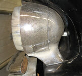
The other challenge is that the 1961/1963/1963 Imperials have their headlights in pods. I think they are the only post-WW2 cars with podded headlights. There isn't room in the pod for an LED heatsink. I'm also concerned that the pod would retain too much heat and burn out the driver electronics for LEDs.

HeadlightPod.jpg HeadlightPodFront.jpg
 

F-22

Well-known member
Joined
Jan 23, 2022
Messages
1,830
The "approved" LED bulbs in Europe are the "Osram Night breaker". I'm convinced those work fine in regular reflectors though they're not cheap...

Tbh the only sealed beam I ever saw was on a car was on a restored WW2 Willys jeep, and even those were usually swapped for replaceable bulb reflectors. I also had a CB360 imported from California that had a sealed beam reflector. Over here in Europe, I think the bulbs were always replaceable.

That definitely complicates it, though I'm sure you can fit generic reflectors inside. Cooling can definitely be an issue too though...
 
OP
R

rdoty

ALLIANCE MEMBER
Joined
Feb 7, 2018
Messages
647
Location
Massachusetts
The sheer number of wires and connectors in a car electrical system can be confusing. Fortunately there is a resource for working on wiring – the wiring diagrams contained in the factory service manual. These are absolutely vital to working on the electrical system!

Intimidating at first glance, a wiring diagram is actually your roadmap to success. They provide a complete picture of every wire in the car from battery to final ground, including all connections, switches, junctions, and plugs.

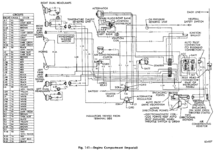
Consider this wiring diagram for the engine bay of a 1963 Imperial:

ImperialElectricalEngineCompartment.png
1963 Imperial Engine Bay Wiring​

This diagram shows everything from the headlights on the front of the car to the bulkhead connector that goes through the firewall into the passenger cabin. It shows all the wires and where they are connected. Each circuit is labeled, such as A-1, H-3, or L-9C.

ImperialElectricalEngineCompartmentDetail.png
Cropped wiring diagram showing more detail.​

The chart on the left side of the diagram lists each circuit, the wire size, and wire color. Looking at the bottom right corner of the wiring diagram we can tell that circuit L-9C is a 16ga white wire that goes to the left most headlight. Tracing this across the diagram we can tell that L-9C goes to a 3-way connector, where is is connected to L-9E. L9E then joins with L-9D and L9. L-9D goes to the right side headlights and L-9 is grounded at the voltage regulator ground point. All of the L-9 wires are 16ga white wires. OK, L-9 is the headlight ground.

Right above L-9E is L-4D. Here is where we can apply some outside knowledge. We know that the outermost right and left headlights are combination Hi beam and Lo beam headlights, while the inner two headlights are Hi beam only. The wire that goes to all four headlights is Hi beam and the wire that only goes to two headlights is the Lo beam. Careful examination shows that L-3 goes to all four headlights, so it is the Hi beam. L-4 is the Lo beam.

Based on this we know that circuit L-4 is a black 16ga wire for Lo beam headlights and L-9 is a red 16ga wire for Hi beam headlight. Tracing the Lo beam wire, L-4D connects to L-4C which connects to L-4B which joins with L-4. L-4 then goes to Pin 1 on the large bulkhead connector on the firewall. If we go to the cabin wiring diagram we will discover that this wire goes to the Hi/Lo switch, the headlight switch, and ultimately a power source.

The same approach works for the parking light and turn signal. Again, we have background knowledge: the bulb for this grounds through the bulb base, directly into the socket and ultimately the car body, so all wires going into the socket are power. Parking lights are common, and will have a common power wire. Left and right turn signals are independent, and will have separate wires. Circuit L-6 is common to both sides, so it is the parking light. Looking at the left side of the car, L-6A is an 18ga yellow wire that joins to L-6A and L-6. L-6 goes to pin 6 on the large bulkhead connector. Inside the car it connects to the headlight switch.

This means that D-6, an 18ga light green wire that goes to pin 8 on the large bulkhead connector is the left turn signal. Circuit D-5, an 18ga tan wire going to pin 5 on the large bulkhead connector, is the right turn signal.

Because I’m easily confused I clearly label both ends of each wire when I’m working on a wiring harness with both the circuit number and the function – for example, “L-4D Left Headlight Lo Beam” or “L-3C Left Inner Headlight Hi Beam”. This makes life much simpler the next time I’m working on the electrical system – both for the function of the circuit as well as the circuit number for tracing across the wiring diagram.

This wiring diagram is actually fairly simple – others get much more complex. I find it useful to copy or print out wiring diagrams and trace circuits I need to follow with a colored highlighter pen. This makes it “easier” to follow a circuit end to end (or middle to middle), as well as keep track of multiple circuits. You don’t want to do this in the actual factory service manual since the page will become unreadable after tracing a few circuits. It is also easier to take one or two sheets of paper into the car while you are working on it rather than to drag the large factory service manual around. As well as making it easier to take notes while you are working.

With a set of wiring diagrams, a multimeter, and some patience and persistence you can tame the dragon of electrical wiring!

At least on old cars – modern cars use communications networks. These networks start with CANbus (Car Area Network bus) and are migrating to Automotive Ethernet. Yes, a variation of the same networking protocol used for computers! I stay far away from the new cars; these old cars are enough of a challenge.
 

Jehannum

Well-known member
Joined
May 3, 2012
Messages
1,368
Location
Albuquerque, NM
F-22, the Imperial is currently running sealed beam halogen headlights. Remember those?? About the only thing you can say for them is that they are less bad than straight sealed beam headlights... I'm looking at getting some replacement headlights that accept H4 bulbs and then use some of the 65 watt bulbs in them.

I've read bad things about replacing standard bulbs like H4 with HID or LED - bad light pattern in reflectors that aren't designed for these bulbs. Apparently you have seen the same thing. Haven't seen anything about TUV listed bulbs; these might actually work.

The other challenge is that the 1961/1963/1963 Imperials have their headlights in pods. I think they are the only post-WW2 cars with podded headlights. There isn't room in the pod for an LED heatsink. I'm also concerned that the pod would retain too much heat and burn out the driver electronics for LEDs.

HeadlightPod.jpg HeadlightPodFront.jpg
Hella's housings for H4 halogen bulbs are DOT approved and have substantially superior performance to the old sealed beam wagners. It's on my to-do list for my '67 GTO. I already did them in my '71 240Z.

The drawback is that, in order to save the wiring and headlight switch, you should run them on relayed power.
 
OP
R

rdoty

ALLIANCE MEMBER
Joined
Feb 7, 2018
Messages
647
Location
Massachusetts
Jehannum, the housing/reflector and H4 bulb upgrade are also on my to-do list for the Imperial. Daniel Stern has moved from Cibie to Koito, so I will probably go with Koitos. Having said that, do you have a good source for Hellas in the 5.75" size?

(Side note - you have good taste in cars!)
 
To avoid these ads, REGISTER NOW!
Top Bottom