To avoid these ads, REGISTER NOW!

Vernon Light Mill/Jig Borer Restoration

Teter09

Well-known member
Joined
Sep 20, 2012
Messages
56
Location
Central Florida
I've been researching and searching for a light duty mill for a while now. I'm limited in space so those devout 'get a Bridgeport' comments don't really apply as I can't house one. I'd basically resigned myself to a Sieg X3 or eqiuvalent when I saw this pop up on Craigslist. I realize some folks will instantly tell me this isn't a mill, except for my lighter material purposes, it will work just fine. Also, the ways are dovetailed and not the simple sit in style so they won't move on me when milling. Then again, the heaviest thing I'd be doing is 1/4 thick annealed steel. I'm confident it will work for me.

Couple pics before I got it home. It is about 6 feet tall to the highest point on the pulley cover when closed, and weighs about 900 pounds.
View media item 45277
View media item 45276

Trying to find information about this machine just flat out *****. There are few other people who have one (at least who have posted pictures or comments about them online) and those who have, they have the Sheldon-Vernon version which came about in the 50's. The machine tag below shows I have the true blue Vernon machine but I've been unable to figure out the year of manufacture. There was a single document over on vintage machinery, but its a sales pamphlet and not a manual unfortunately. There is a pretty decent write up about the Sheldon version over on http://www.lathes.co.uk/vernon/ but certain things are very different between the two as I've found out in the tear down for cleaning.
View media item 45278
In order to transport it, I had to take the head portion off and luckily at a few hundred pounds, I could get a friend to help me lift it on to my bench to tear it down. The gentleman I got it from hadn't really been using it, and things were sticking all over, which suggested I needed to tear it down to relube and fix any issues.
View media item 45279
Motor was slightly gritty on the outside but was NOTHING compared to the inside.
View media item 45281
After removing the power switch, you can see a couple of the different colors. This machine had quite a few all over it. The column seemed to have more of a mint green in spots, where as under the power switch you can see the avocado green? The machine grey color had been thrown on at some point with no regard to properly taping off or disassembly, since the dials were slopped on, the table in the T slots and even the belts had been painted.
View media item 45280
 
Last edited:
To avoid these ads, REGISTER NOW!
OP
T

Teter09

Well-known member
Joined
Sep 20, 2012
Messages
56
Location
Central Florida
Front of the machine with the spindle which reaches in to a sleeve and then up in to this front pulley. Notice the color on the tip where the cover attaches? Nope, not mint green and no, not avocado green either. Its more a kind of pea green. Thats green #3!
View media item 45292
This is kind of a cool pulley which I've never seen before. The knob on the top left can be pushed down, which locks the upper 4 slots of the pulley with those of the lower two for more speeds than just the 4 most drill presses come with for example.
View media item 45300
Partial view of the motor mount bracket, avocado green! Very Very heavy and stout piece of metal.
View media item 45299
Rear view now that the motor and motor mount have been removed. This is the middle pulley which allows for multiple speeds. The bolt you see sticking straight back pushes against the motor mount to tension up the belts.
View media item 45291
Center pulley removed, as you can see...tons of **** inside this upper housing. The pulley cover does have a hole in it, which allows the spindle to pass through it when the head unit is raised and thus dirt and junk can get in, but this is kind of ridiculous. Also, the head unit slides vertically, which at a guess of 80-85 pounds is REALLY rough to lift....except it has a counter weight which is connected to it by the chain you see. The weight is down inside the base (didn't take pictures since its just a hunk of metal in the shape of a cylinder).
View media item 45305

Forgive me, there are some things I just was too involved in, or simply didn't take pictures of due to the nasty nature of the cleaning and not wanting to touch my phone. I wanted to document this as best I could for those folks who might come across this machine in the future and want to learn more, or perhaps want to see some pieces that the need to replace or clean up.

This is with the handle removed.
View media item 45297
Opposite side of the head unit, there is a knob here which engages or disengages the fine wheel control as opposed to the gross movement handle.
View media item 45293
Top down view of the fine depth adjustment. Shows the paint slop from the poor paint job as well as how the head unit casting connects to the gross control.
View media item 45302

Cover removed which holds the depth assembly inside the head? Not quite sure what to call it, picture of what I'm talking about below.
View media item 45296

This dohickey! Believe it or not, this was wiped down and lightly de-greased in this picture. For some reason, despite the fact there was an oil cup up top, there was a TON of grease inside the head. Made no sense to me!
View media item 45298
This is the fine depth adjustment. The wheel is visible in the lower right corner of the picture. I took this to remind myself how it all went back together and which pieces.
View media item 45294
Inside view of the fine depth adjustment spindle. Bearings are visible and once removed...PACKED with grease but still wet from oil as well. Not sure what happened to it.
View media item 45295
 
Last edited:
OP
T

Teter09

Well-known member
Joined
Sep 20, 2012
Messages
56
Location
Central Florida
I didn't really take any pictures of the table. Not sure why, I think I just dove in and pictures were an after thought. It had an old Brown and Sharpe Vise with no jaws on it, which I threw in my electrolysis tank after being de-greased. The table was absolutely overloaded with grease. Fortunately what little use this thing saw, it was aluminum. So the hard turning knobs that were loaded with grease and swarf wasn't cutting grooves or doing damage to anything underneath. Also, the 2 copper spindle nuts were somehow pretty well shielded from everything, so while the grease was REALLY packed in there, it was at least clean of foreign material.


This is one of the few pictures I took which was involved with the table. This is basically an assembly that is pressed to the bottom of the base which holds the table, which also holds a copper nut for the Y travel spindle.
View media item 45304
Copper nut for the Y travel table spindle. The grey portion with the set screw is a narrow steel but really, and screws on to the copper nut, but I'm not sure what the steel nut was for actually.
View media item 45303
Motor unmounted, with the sleve which connects to the pulley assembly shown previously. I assume the rubber sleeve was to help reduce vibration and allow for a less than precise alignment, any help or ideas or can anyone confirm?
View media item 45301
The zerk fitting on the motors had a slight red color on them, I had read in years past that red meant grease as opposed to oil. OYE was there grease.....

This is the top of the motor, notice all the grease along the upper bell housing and then on the stator as well?? Yuck...what a MESS!!
View media item 45283

Here is the armature removed (and as you can see covered in excess grease) but still sitting inside the lower bell housing. Look at the fan and whats below!
View media item 45290
I couldn't believe the previous owner had put in THAT MUCH GREASE....
View media item 45284
Here is the armature sitting on top of a cylinder so I can start cleaning off all the nasty grease.
View media item 45286
At this point, everything had been stripped apart, de-greased, and rust removed. For this I used electrolysis on larger parts like the base, the column and the head portion which the spindle passed through, sand blasting on a few parts like the motor mount bracket and counter weight, evaporust on many smaller nuts and bolts, or WD-40 and scotchbrite pads on the different metal pieces like the table and measurement dials so the grime would come off...but not completely remove the patina and the character.

Oh, one really cool thing on this machine is the coolant/swarf catcher. Not sure what its called, but its basically a 14 gauge steel tray below the table base but above the machine base. It was covered in **** and rust all over, so I took a wire brush to it on the angle grinder (actually my dad did). Cleaning it all up, he and I learned that the corners were cut and formed and forge welded. I thought that was pretty cool since I'd never seen anything like that before. Any sort of shapes in metal today are just sheet metal or would be bent and bead welded. Gotta love old craftsmanship methods!

I used a self-etching primer and also some filler primer on some spots to even out some gouges.

This is about the only picture I have of any parts in the primer phase. I just primed the inside to prevent future rust, taped off the openings so I could spray the exterior with the enamel. I re-assembled the motor to make like a bit easier in painting it.
View media item 45285
I couldn't find the original color anywhere or even suggestions by anyone. I'd even looked at the hortizontal mills by Vernon or Sheldon-Vernon for some ideas and it seemed even those varied quite a bit. So I opted to try to go for a machine grey in the Sherwin Williams industrial enamel.

I spent hours taping parts off and plugging holes so I could spray it on in a mixture of Paint to Penetrol of about 16 ounces to 3 ounces. I tried 4 - 1 but in the Florida Humidity...it would run. So I toned it down some and sprayed it on. It took 12 hours until it was dry to the touch, which was great in allowing me to fix mistakes but HELL on trying to keep things from getting dust or whatever on them in my garage!

After 24 hours I examined everything....and realized the Sherwin Williams guy misunderstood my color choice. He thought I'd selected a color which was quite a lot lighter than what I wanted. When spraying it on, I assumed it would darken as a lot of enamels do. Not my luck! Oh well, lesson learned!

I sprayed 2 coats on most parts of the mill for durability, 3 on the machine base because I know it will get kicked and dinged a lot!

So here are two shots of it back together from different angles. It is lubed and once I get it wired back up, ready to go. I still have the machine label, the on and off switch label, and both motor labels off it currently, slowing cleaning them up before popping them back on, but that won't hold me up using the machine!

View media item 45288
View media item 45289
I can take additional pictures of it back together if wanted, but I wasn't sure how much interest this machine would bring on here.
 
Last edited:

CoopVA

Well-known member
Joined
Jan 20, 2014
Messages
2,144
Location
Virginia
Wow! Great job! Would love to see more pictures...

I just got done with a South Bend lathe. It was in bad shape when I started, but it was a labor of love. A friend of mine told me that with 200 hours into it, you now have a $15,000 lathe... LOL...

I've also got a Sheldon-Vernon Type 0 mill. Not sure if I'm going to give it a full restore yet. I want to run it some before I decide. I've not been very successful finding a lot of info on the Sheldons...

Sent from my iPad using Tapatalk
 

Scimonetti

Well-known member
Joined
Aug 25, 2014
Messages
431
Location
VT
Wow, you did a great job documenting the whole project! Did the electrolysis remove all the paint, or did you have to scrub after?
 

larry_g

Well-known member
Joined
Apr 28, 2007
Messages
16,892
Location
oregon
In one of the pictures you mentioned the steel nut on the brass lead screw nut. Did you figure out that is for the backlash adjustment? Also curious in did the machine come back into tram when it was reassembled? Have you found the Sheldon lathe group? One of th members there, John Knox, was a Sheldon employee and may have some information on this machine. You have a good looking machine there and I hope that it does the job you want to do. One of the defining differences between a mill and a drill is that the mill will positively hold the bit against all forces where the drill will only hold against forces linear to the C/L of the spindle.

lg
no neat sig line
 
OP
T

Teter09

Well-known member
Joined
Sep 20, 2012
Messages
56
Location
Central Florida
What spindle taper does it have?
Looks like it will be a lovely little machine to use!

I'm not certain actually. I've read different ones, some say B&S #7, others #9, others have said the LB Collets and I think some say a cheaper option is the B&S #00. It came with a few Double Z collets that seem to work just fine.

Wow, you did a great job documenting the whole project! Did the electrolysis remove all the paint, or did you have to scrub after?

The e-tank removed most of the paint along with the rust. Any scrubbing was more along the lines of scrubbing the 'gunk' off of it not much elbow grease at all.

In one of the pictures you mentioned the steel nut on the brass lead screw nut. Did you figure out that is for the backlash adjustment? Also curious in did the machine come back into tram when it was reassembled? Have you found the Sheldon lathe group? One of th members there, John Knox, was a Sheldon employee and may have some information on this machine. You have a good looking machine there and I hope that it does the job you want to do. One of the defining differences between a mill and a drill is that the mill will positively hold the bit against all forces where the drill will only hold against forces linear to the C/L of the spindle.

Aha, backlash adjustment! No, I didn't know but thanks for explaining it to me. It makes sense but I have not fully adjusted anything on the machine yet. So far I have not checked the tram. The gib adjustment on the head took some doing to get it so that the vertical travel was in line, but that is as far as I have gotten (well that and the table travel now is inline as well). I know from what little I have read the tram adjustment winds up being shims to one (Or more) of the column bolts which mount it to the table base.

I will work on getting some more detailed pictures and I think it will be more readily understood as to which pieces I'm referring.

I am in the Sheldon group, and when I asked for advice, if other members had one, I got just one response that told me to check out Vintage machinery and the Lathes.co.uk vernon page....which I mentioned I had already looked at in my inquiry!

As for the mill vs drill....I am just going by what I have read from folks and also some of the advertising materials. When the machine was demonstrated to me, it took 1/2 cut out of 2 inch thick aluminum (the end mill in the machine and a scrap piece of metal he had around). I am not a machinist by any means but I hope that is a decent enough indication that it can do small projects like I would be performing. I'm not a production environment and I think/hope this will be a solid machine for me to learn on. If I learn the short comings of this, no big deal, it will help me on my journey!
 
Last edited:
To avoid these ads, REGISTER NOW!

chadrebuck

New member
Joined
Jul 22, 2013
Messages
4
I just picked up one of these machines this past weekend. It has a collet for for 1/2" bits and a small one that may be 1/8" but I think I'd like one for 3/8" bits. What collets are a fit for this machine? I suppose I could try to make a collet just to see how it turns out but I'm new to the lathe as well.
 

Charlie W.

New member
Joined
Aug 18, 2020
Messages
1
Location
AL
Looking for photos or parts manual for this Vernon Jig Borer showing how bearings, spacers and shims go in the quill lift gears. Thanks.
 

chadrebuck

New member
Joined
Jul 22, 2013
Messages
4
I am in the process of making a collet. I haven't taken the spindle apart so I can't help with any info. I did take the tables off and cleaned all rust and stuff possible. Added some shims so the gibs could be properly adjusted. The collet will be the first thing I've really made on my lathe. I've cut the taper and will soon drill it out for 3/8 since my 1/2 and 3/16 collets are in good shape. My 3/8 is cracked at the large end from gripping with vise grips to remove. The collets do tend to get stuck a bit in the spindle so it's a pain to switch them. I'll try polishing them to see if that helps. The spindle bore feels perfect and there is no oil in there.
 

chadrebuck

New member
Joined
Jul 22, 2013
Messages
4
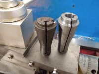
I finally got around to making a collet for the machine using my mini lathe. To cut the slits I used the jig borer with a slitting saw. This is the first collet I've made. I still may sand, polish, and harden it if I can find an easy way to do so. To remove the collets I grab on to the end with vise grips with only with enough force to wiggle it loose. The collet I made was to replace one that was already broken when I got the machine. My hope is that with hardening that will prevent much of the marking from the vise grips.
 

Attachments

  • 1.jpg
    1.jpg
    124.5 KB · Views: 23
  • 2.jpg
    2.jpg
    109.9 KB · Views: 21

larry_g

Well-known member
Joined
Apr 28, 2007
Messages
16,892
Location
oregon
I finally got around to making a collet for the machine using my mini lathe. To cut the slits I used the jig borer with a slitting saw. This is the first collet I've made. I still may sand, polish, and harden it if I can find an easy way to do so. To remove the collets I grab on to the end with vise grips with only with enough force to wiggle it loose. The collet I made was to replace one that was already broken when I got the machine. My hope is that with hardening that will prevent much of the marking from the vise grips.

Take a close look at your broken collet. It has a taper on the nose extension that you have to squeeze into the nut. This taper matches an internal taper on the nut that will pull the collet if the cutter is still in there preventing the collet from collapsing. Your nut may also be worn out and the taper gone requiring a new nut.

lg
no neat sig line
 

chadrebuck

New member
Joined
Jul 22, 2013
Messages
4
Thanks for the input. I took a look at the collet nut and the 3 collets that came with the machine, including the collet in the picture. I can't actually make out any taper. The picture does appear to show a taper but I can't see any taper when looking at the nut or collets directly (magnified 5x). It would be useful to have the nut grip the collet to make them easy to remove. Maybe the nut and collets I have aren't original and were created without the taper?
 

Cyclotronguy

Active member
Joined
Mar 24, 2010
Messages
31
They were in the day very high quality machines, made in SoCal. I had one with all the collets and somewhere I have the prints for the collets from Hardinge Bros.

I sold mine to a guy and he didn't want the base, he wanted it bench mounted. To this day the base lives with me, although now it has a 24" x 24" x 1.5" plate of A36 on top of it
 
To avoid these ads, REGISTER NOW!
Top Bottom