To avoid these ads, REGISTER NOW!

Welding in patch panels

AJ.

Well-known member
Joined
Jan 30, 2016
Messages
238
Location
South Australia
Time to make the outer patch panel.

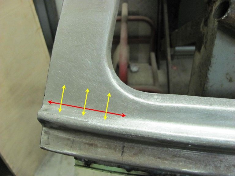
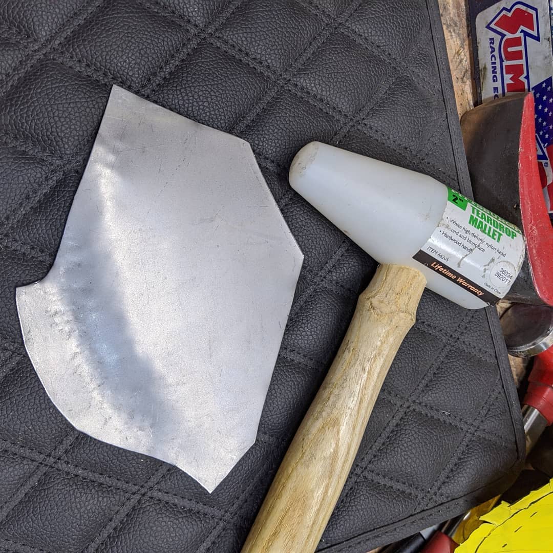
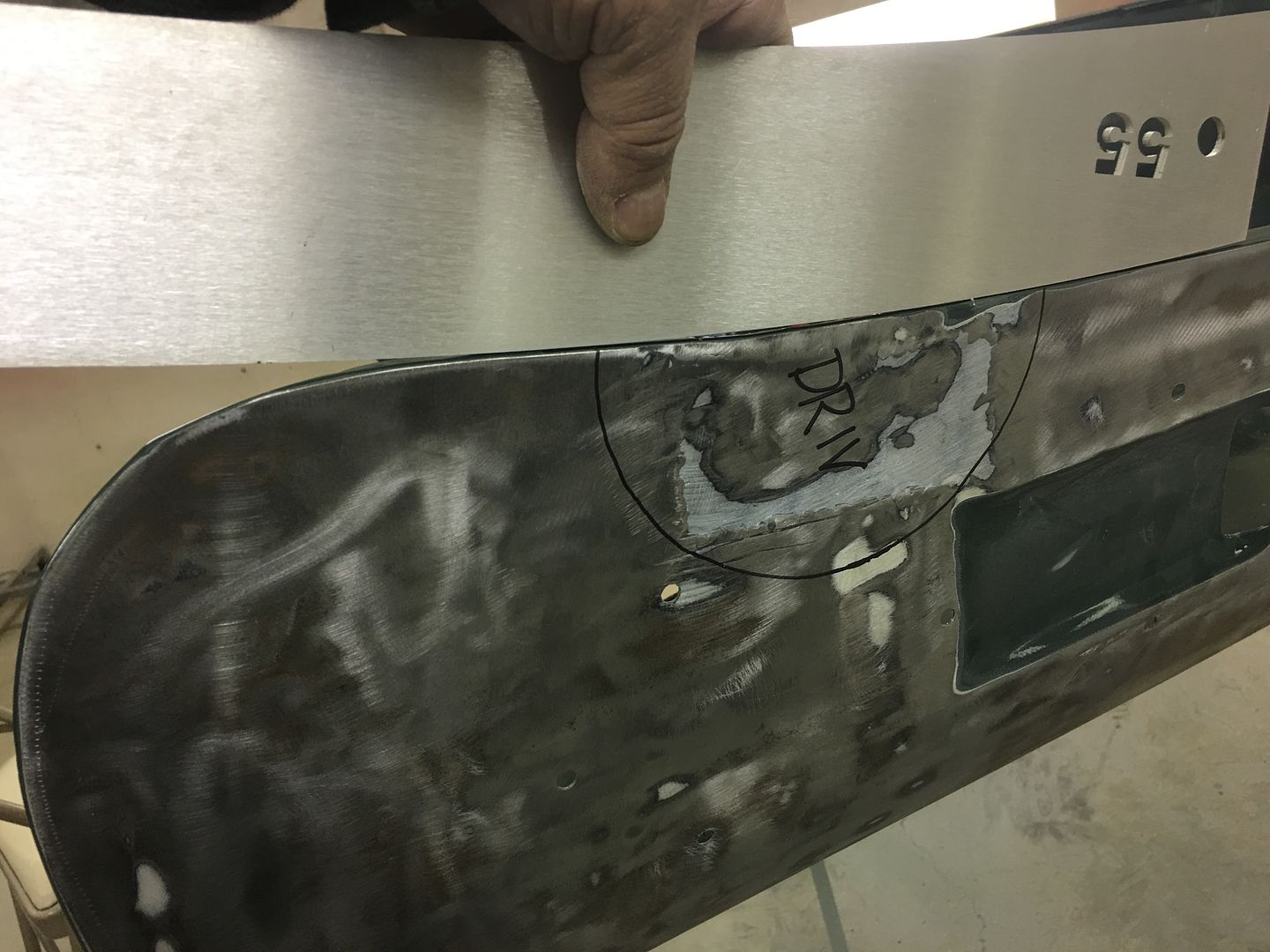
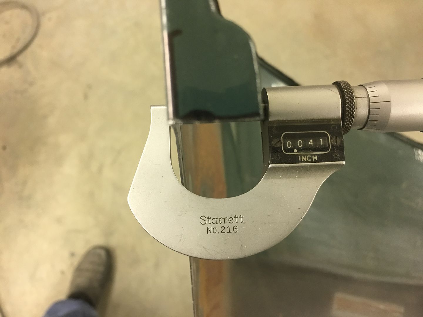
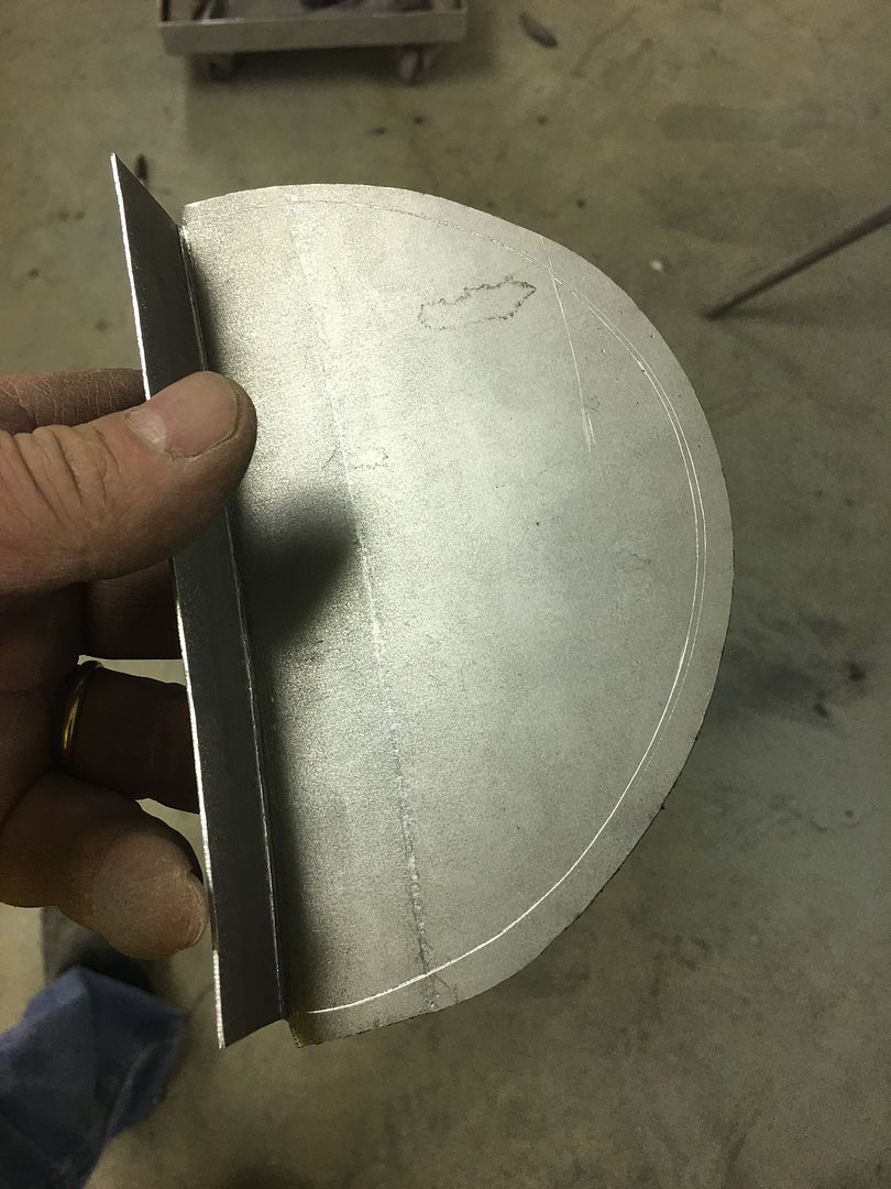
I had the profile gauge I made from the original sill panel, so just a matter of shaping the new piece of steel as close as I could to that profile.

I think I got it pretty darn close for an amateur. The sharp bends I did in my sheet metal folder, the curves where hand formed over a few lengths of pipe.


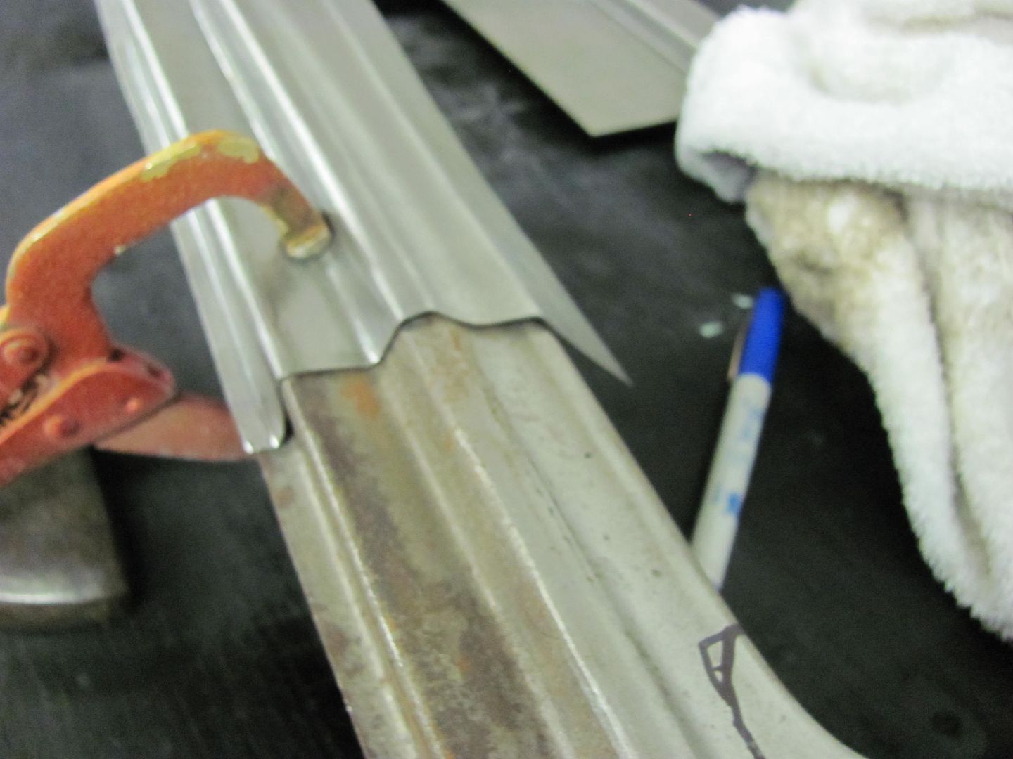
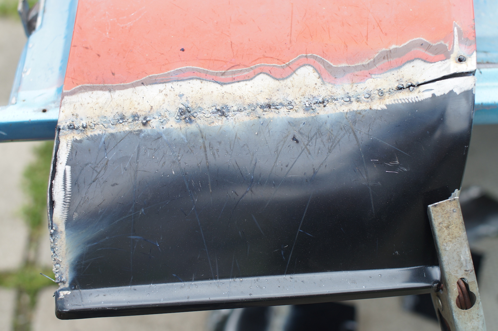
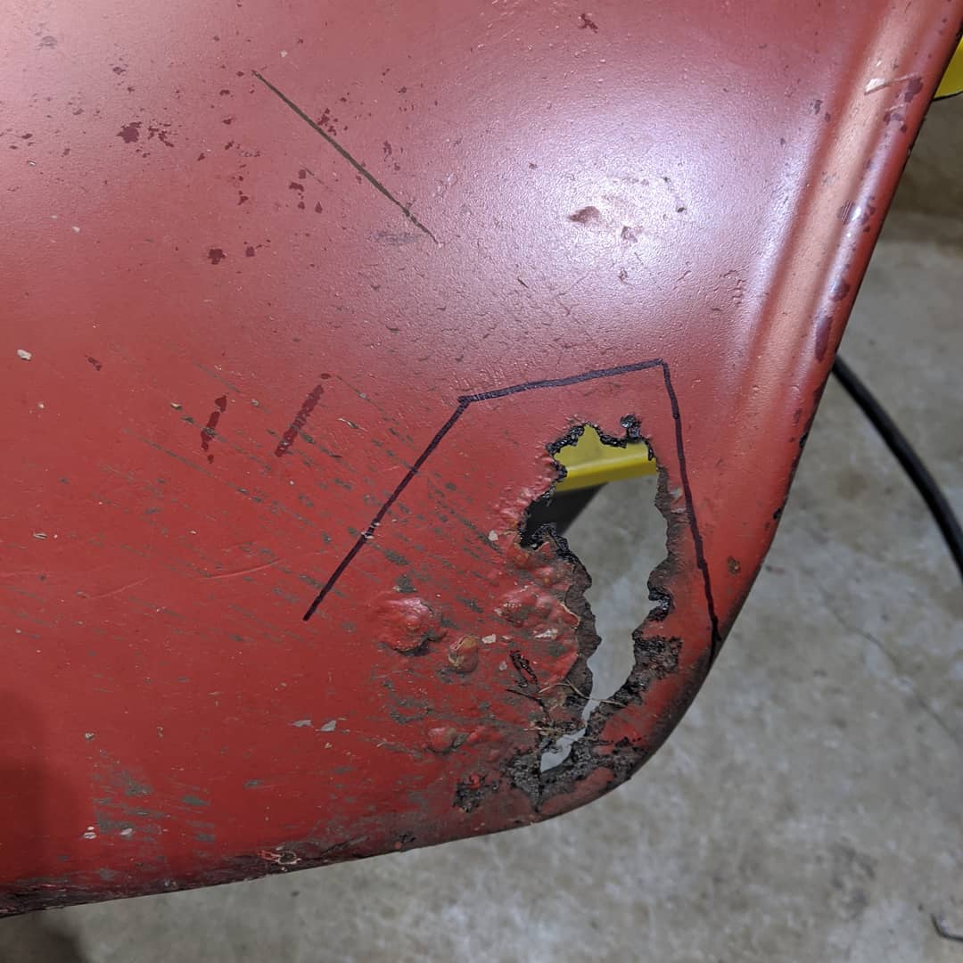
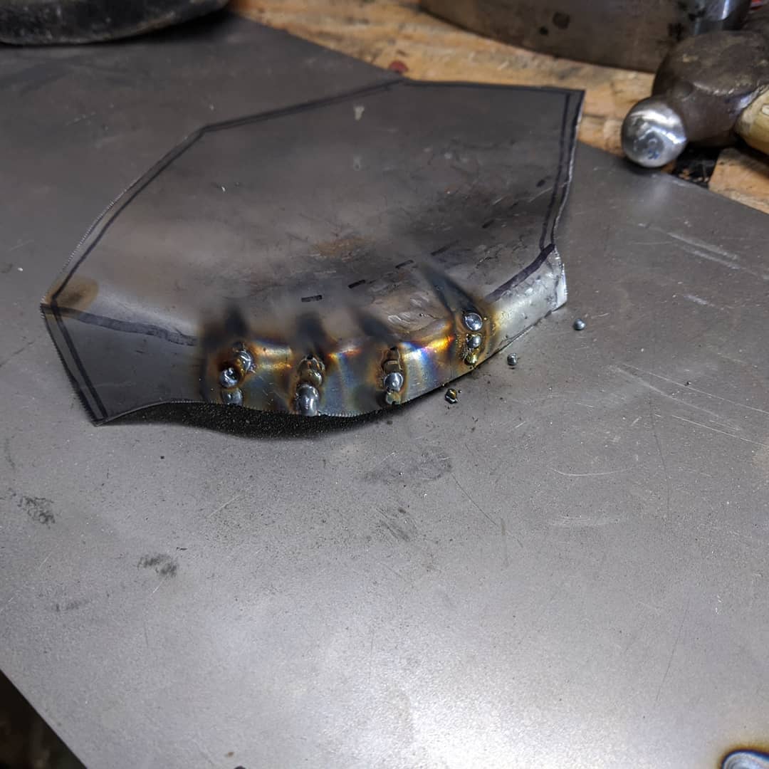
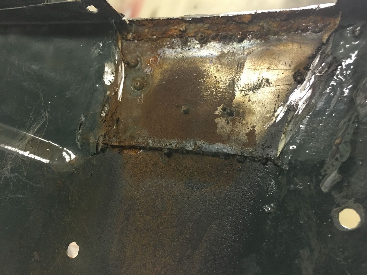
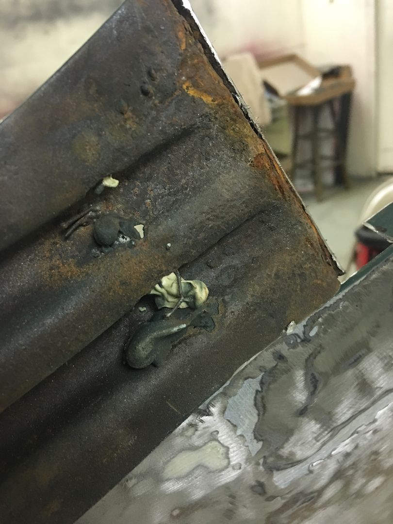
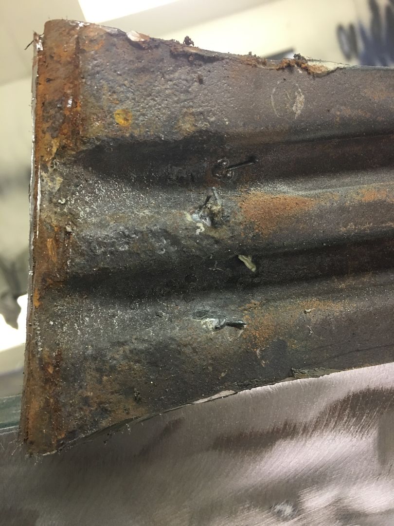
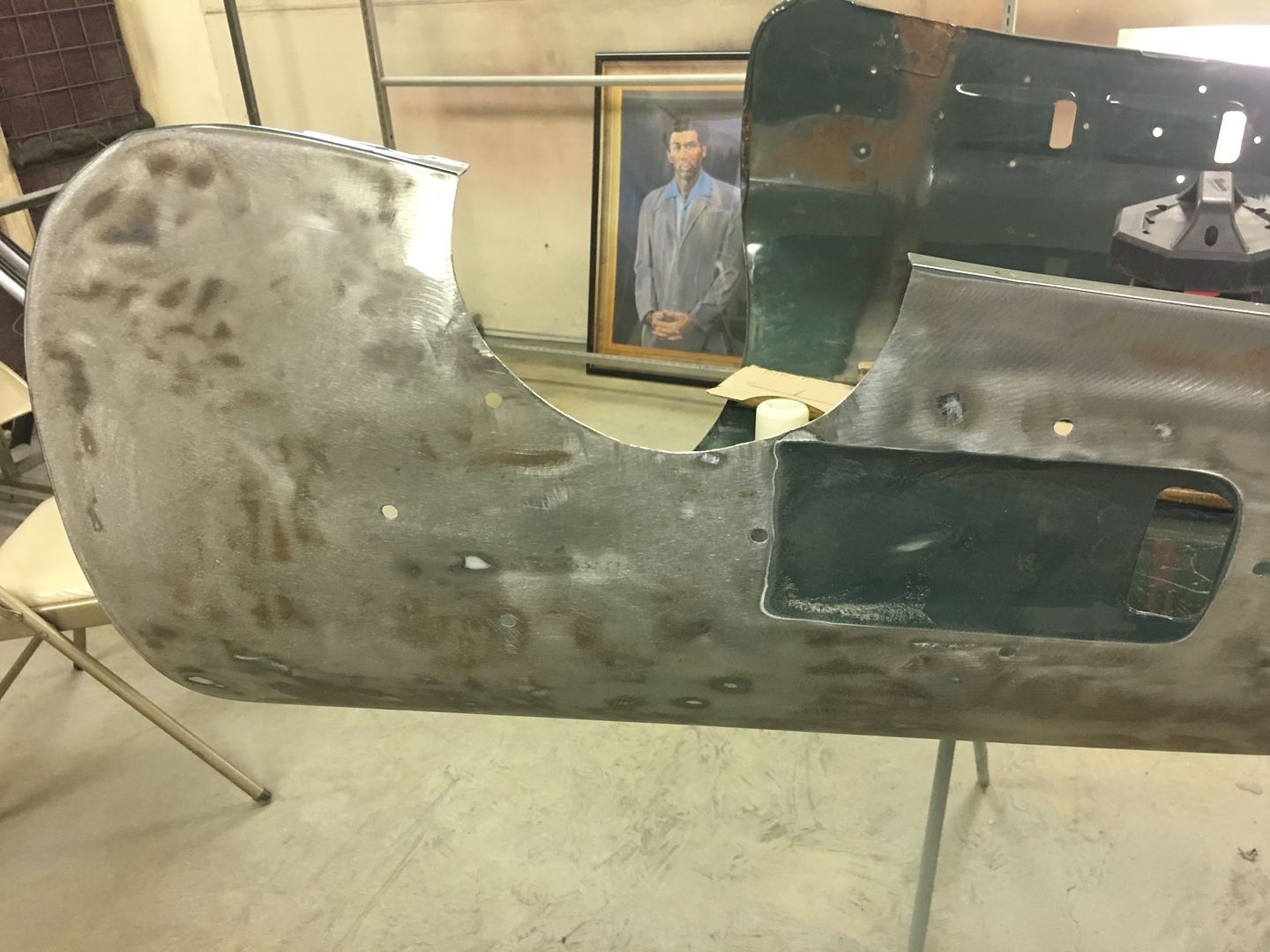
There was a drain in the outer skin, you can just see it in one of the pictures above. I decided to replicate the factory shape of the drain. Fist job was to make a form, which was just an angled slot in old piece of timber. Then clamp it all down and start shaping.


Happy with the end result :)


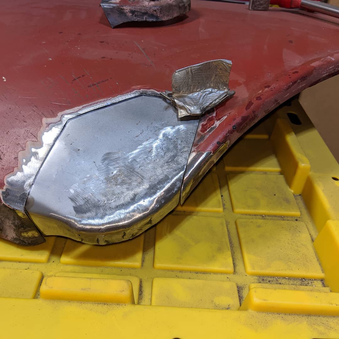
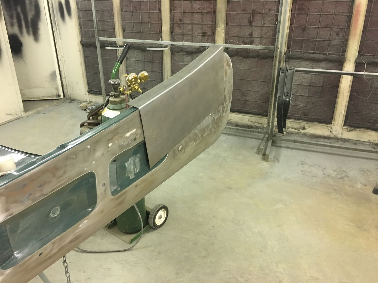
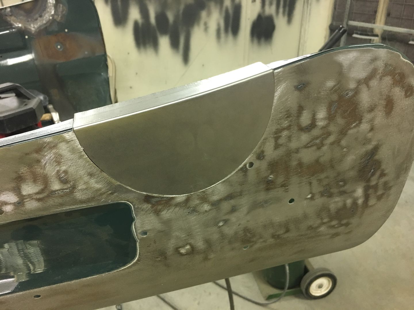
Then a final fit up and trim before priming the inside surface ready for welding in.


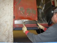
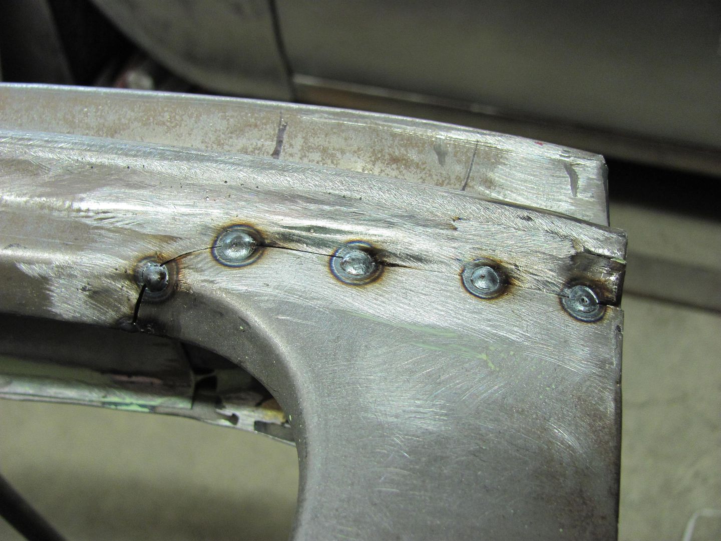
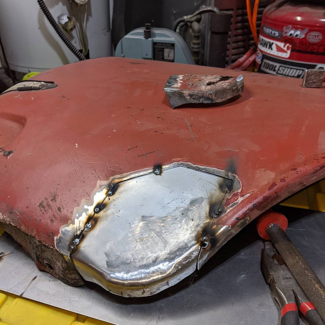
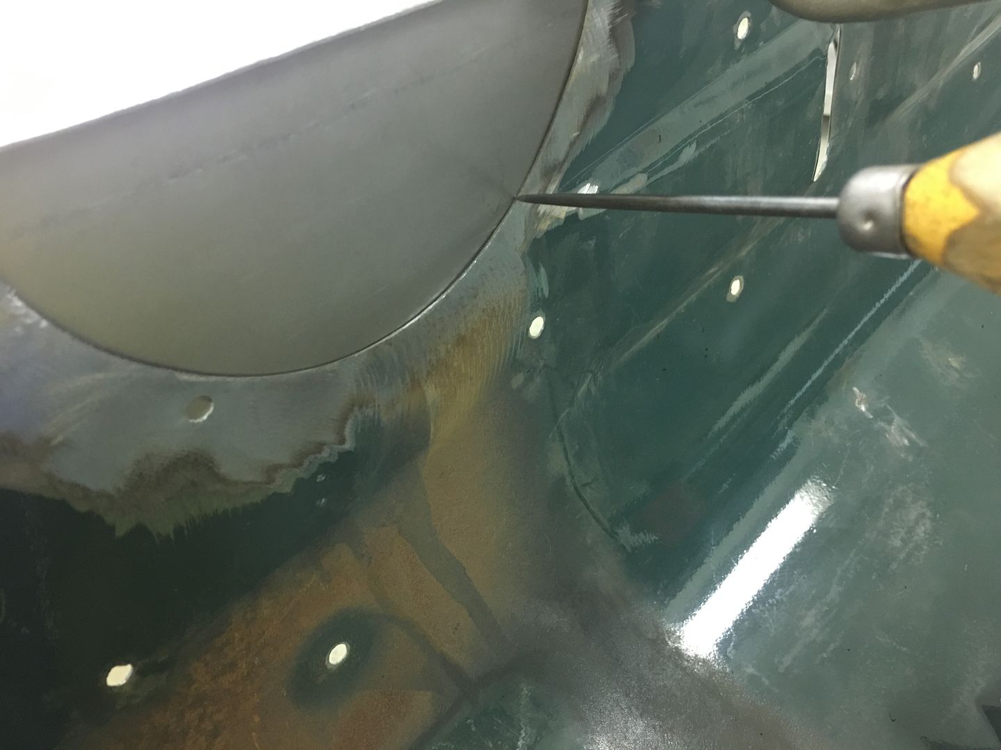
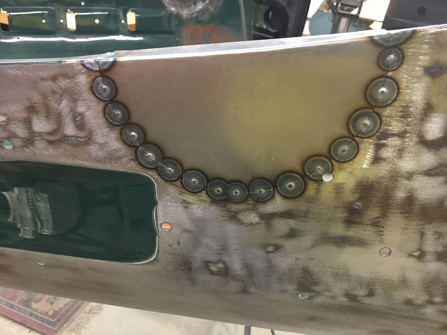
panel tacked in place.


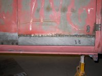
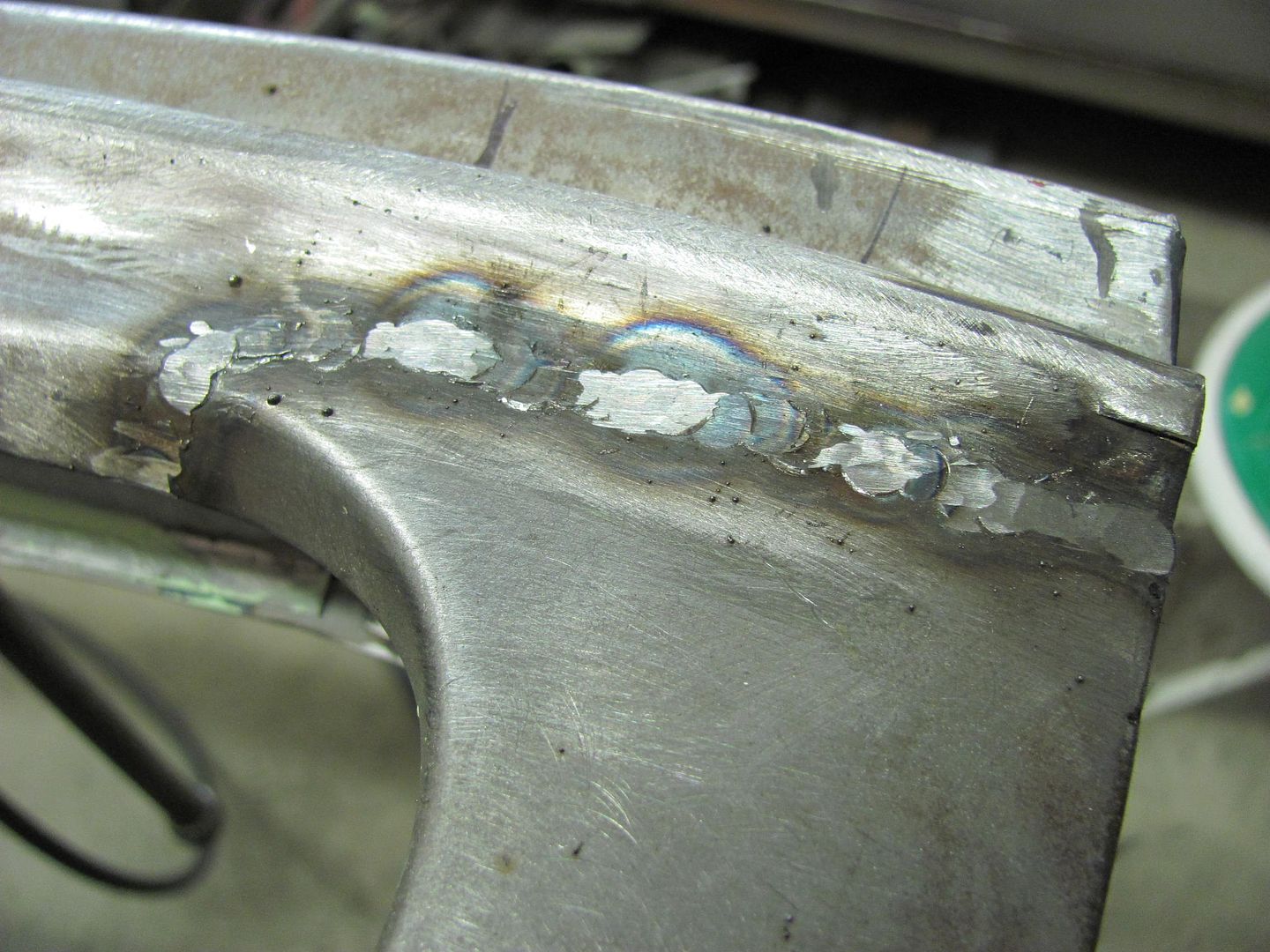
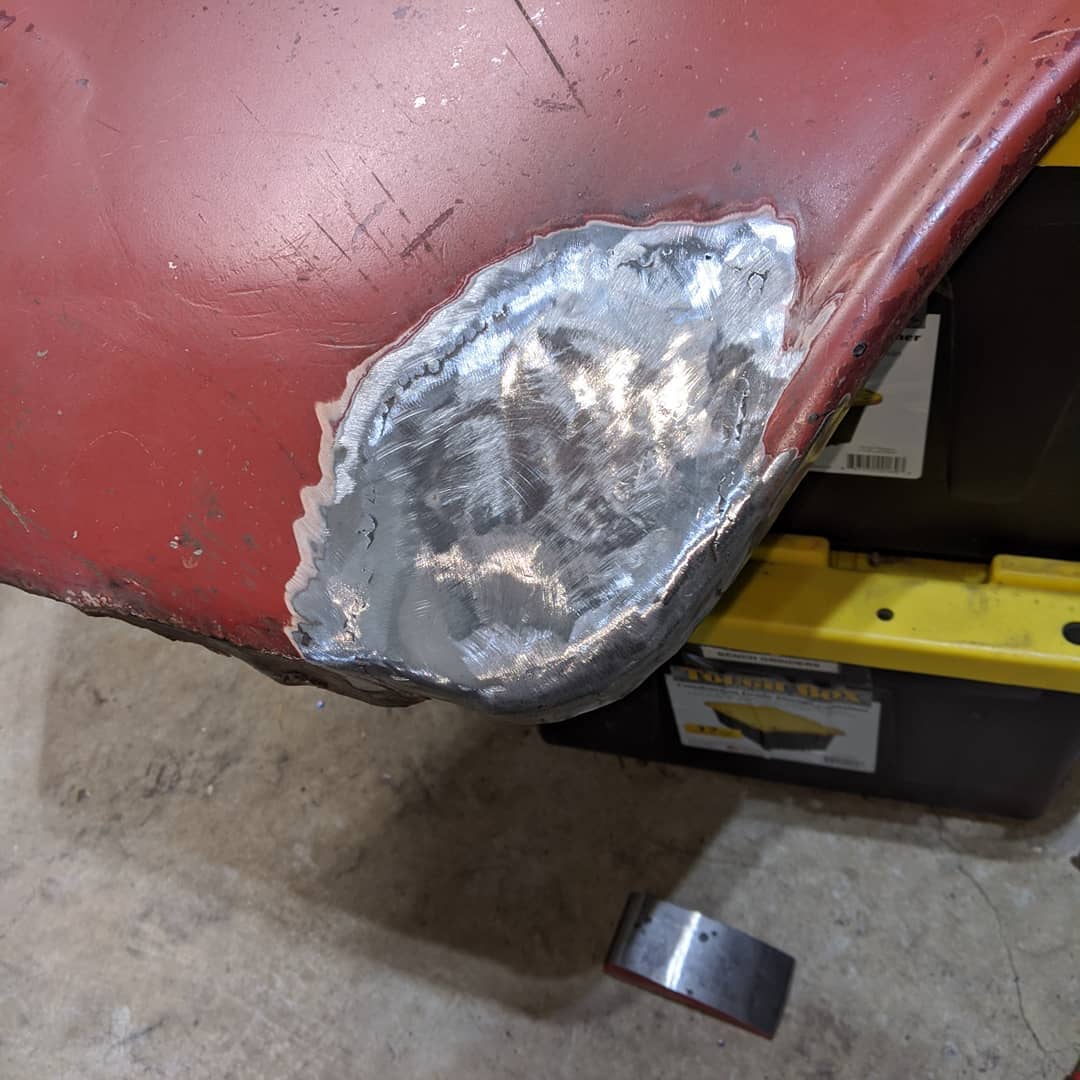
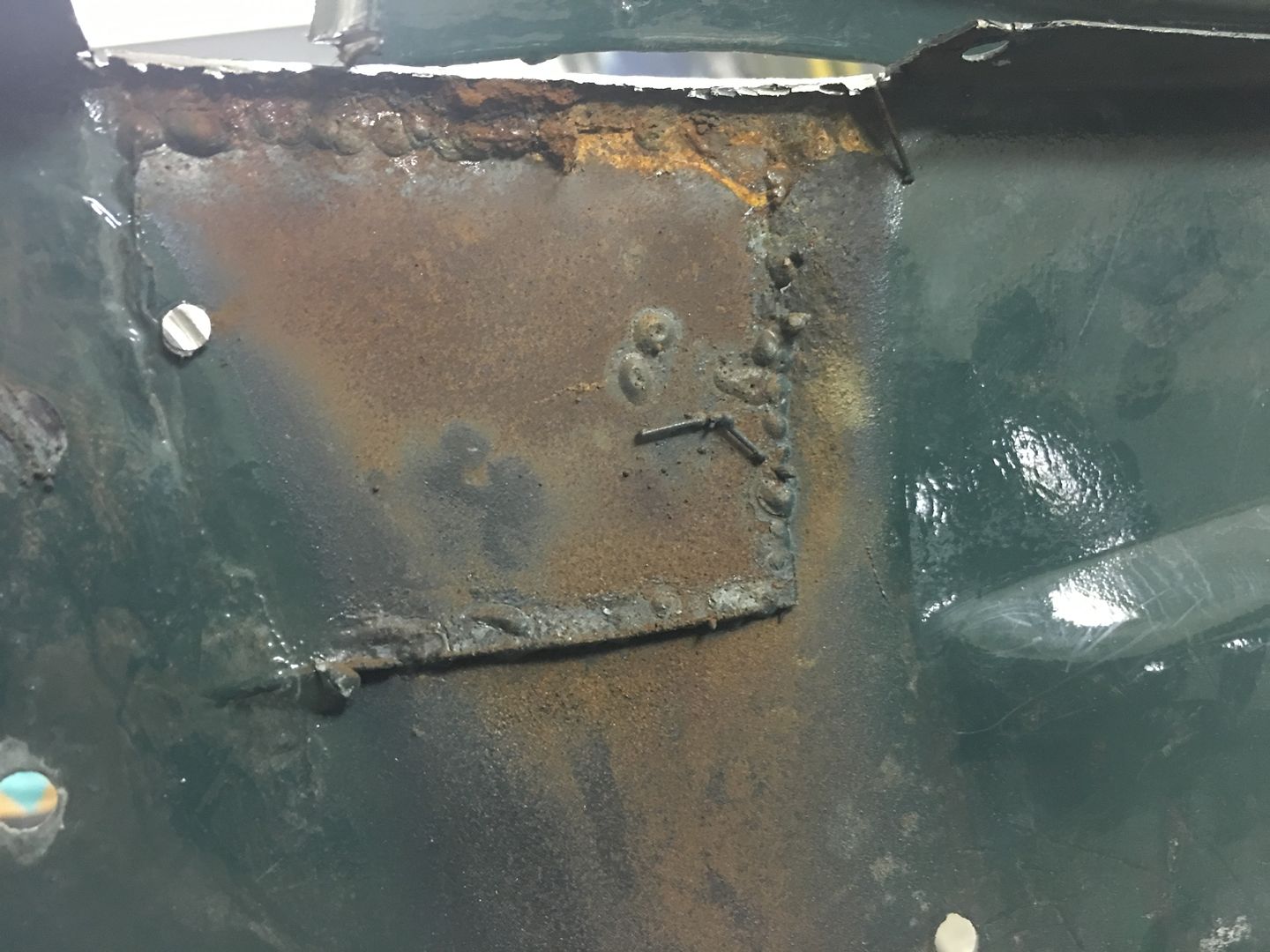
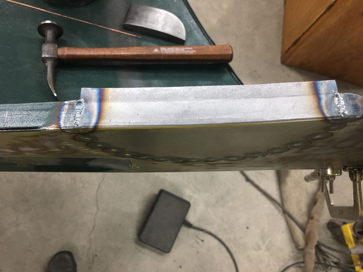
Then the same deal as the last repair, weld grind, weld grind, cool in between, eventually you get a finished repair :)


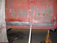
I have to say that I am VERY happy with the way that turned out, I wasn't that confident at the start but stoked at the end :) A few coats of primer should be enough to smooth out the slight irregularities in the repair.

Cheers Andrew
 
To avoid these ads, REGISTER NOW!

6erWebb

Active member
Joined
Sep 2, 2009
Messages
33
Location
Franklin, Tn.
You guys are killing me, I need to post up some pics of some floors I did in a late model BMW lately.

My biggest problem is the welding. My panels are getting better but as soon as I put them in I get a LOT of warpage. How much time are you allowing for between tack welds once you get to the point of final welding?

Im also using an eastwood mig 175, and trying to figure out the tuning.. may be the welder it self but it seems like Ill get a couple good tack welds then out of no where it acts like its run out of gas or lost the ground.
 

AJ.

Well-known member
Joined
Jan 30, 2016
Messages
238
Location
South Australia
I put a tack every 2-3 inches, then wait until it's comfortable to touch with a bare hand, then tack between each tack. I am no expert but that has worked well on my couple of repairs.

Cheers Andrew
 

motoidiot

Member
Joined
Feb 28, 2011
Messages
15
Location
Rodeo, Ca.

darcus

New member
Joined
Feb 5, 2018
Messages
1
Robert....

I am new to the garage journal and just glossed over this thread before going to work yesterday. Holy cow did I pick up a lot of tips! I plan on reading it all again slowly and in detail. I can already tell this is the best thread I have read on welding. This may have been answered already but are you using gas with your mig?

I have a project I would like to tackle for replacing the quarters on a 51 Buick that will take (based on my abilities) pretty extensive fab and welding work and I have done very limited mig work with no gas. I was convinced that what I wanted to achieve was not obtainable with a mig (especially w/o gas) and figured I should invest in a tig unit. This thread leads me to believe otherwise.
 

Bruce Amacker

Well-known member
Joined
Nov 6, 2011
Messages
573
Location
Cleveland, Ohio
Weld a tack about 3/8" long with right hand, left hand has an air gun. Wait 1 second for the blob to harden, then blow 5 seconds with shop air directly on the weld, during this 5 seconds the temp of the weld goes from 1500F to room temp. Proceed with next weld several inches away, moving around the panel. Eventually the short welds fuse together into one long weld. Warpage will be at a minimum if you keep the panel cool.

Grind out with hard disc to remove the mountains, then flap disc to smooth out. If you're normal, mud and paint. If you're really good, high build primer, then paint.:D

The left door in the pictures has already been done, ground out and DA'd.
 

Attachments

  • P1110025.jpg
    P1110025.jpg
    136.8 KB · Views: 235
  • P1150092.jpg
    P1150092.jpg
    145.7 KB · Views: 219
  • P1150100.jpg
    P1150100.jpg
    144.7 KB · Views: 212
  • P1150104.jpg
    P1150104.jpg
    143.8 KB · Views: 207
  • P1150111.jpg
    P1150111.jpg
    144 KB · Views: 214
Last edited:

Zoig

New member
Joined
Feb 20, 2015
Messages
1
Location
Estonia
Weld a tack about 3/8" long with right hand, left hand has an air gun. Wait 1 second for the blob to harden, then blow 5 seconds with shop air directly on the weld, during this 5 seconds the temp of the weld goes from 1500F to room temp.
From what i have understood the rapid cooling of the weld causes it to harden, hardened metal is more difficult to work with and could be brittle compared to slower cooled welds. Or it is something that does not apply to small tack welds as it would cool rather fast even without blowing the air?


Allthough it does not apply to thin sheetmetal, on thicker pieces with tig it is advised to use downslope to avoid crater cracks forming at the ends.
 

banjopete

Well-known member
Joined
Oct 5, 2014
Messages
300
Location
Edmonton, Alberta, Canada
The trick is to do tacks, alternate around the panel and give plenty of time to cool, let them air cool and NEVER accelerate the process with water, damp rag, compressed air. Accelerating the cooling process will create brittle and weak welds that can crack later in time.

This was repeated a number of times earlier in the thread. YMMV but the guys mentioning it have proven the value of the input with pictures and lots of experience. I'm with these guys on the rapid cooling topic.;)
 

mopar4don

Well-known member
Joined
Mar 9, 2013
Messages
103
I would like to patch my trunk lid but because the patch is long and flat I am a bit nervous about warping! What do you guys think?
Also the lid has been seperated (inner and outer) and I have another lid that I can take the patch from.


y4msponPexF86gYfh1PsLy9YFftVbg0ug1yzdtd6lOBnmNR48MqCCqr34PBT_DEiMuED_g-doAWEyZWCxmMyvHoEqPPk76iGYsvFrJdcGXIqoILGjrI6kumoYjeChomxebaSA9kwLAqj1apfaUlAfmBb1GOD6D5vq2chx9mBdlbgatf9rRIlLsiRT0SthkQOa6xmkEjgolZ5CLZrOCqpK4Pvg


y4mMuBFVyVwD27haaLm9tNZnWn17MaFl3pL8eGwjOXI0IwkXibbM0ZTcBvCz38fVjEa2uxqktbYiz6YGP7cAoxGWEJniX405opoIj4wekHvbPLsDQsyif5s_ZYjeCGG4sPW7I4pkjnK4iywH8ONAKF00iJVo376qU06cXyog-faEa8r39kMSgbbozmDU35mkEcFT79eD5ZWQgCfKdE9lybcnw


y4mtuY8zyIBcdnCdf2sz1YhNp7YjUmY0lYYjN8L8BZAc4AChtJulrXoxqw2rOzGkScW2FeMZvsQvFg_HrlkW8lcP1Gc-70U81UeEdxW42eWumM1TuKOVyYG6J0X9h8VYuHDscZ-EdrRJpm57iOdkHC_8HQi7h7TDBFvdeNGRIRb-vaUOIvGoyd3GQN0MWxUXXjh0OaMaDcFtMSa8ymBtVbMxQ


y4m2NZEcPvyg-bjRzaF4LRgU6O0DvnMVbx8Yqek662NBhjQYkpdTndb3z11ndDUmTifvR7lQM_Oi5Wfxgt8eHGKbnntpS0fuK7pEw4uxTHWmSqZcvHhtV7wfBy3fNarSH7Oehby7xQgQyZxc9yDjxABEpkm02wpfqXtqO2dzC96slRXdPSlZ6G8BRsnAx-tcMbpcWEaJnlb5o3IAtzLfHLMEA
 
Last edited:

mopar4don

Well-known member
Joined
Mar 9, 2013
Messages
103
Is the patch donor lid damaged elsewhere that you can't use the entire thing?
I actually have 4 trunk lids. All of them have problems in different areas. (dents, and rust) (1 lid looks like it has hail damage, 30plus dents)
I separated the inner and outer skins on 3 of them, looking for the best one to use. I choose this one because it has a couple of minor dents in the outer flat skin.
 

MP&C

Well-known member
Joined
Oct 21, 2009
Messages
4,396
Location
Leonardtown, MD
If the hail damaged one is free of rust I think I'd rather work out dents than have the headache of fixing weld distortion in a low crown panel, especially since you have the separation of the two parts down to a science..

For the trunk skin shown, I think you'll find a bit more rust than is actually showing, so first I'd come inward from the side just a bit more to get into more solid metal. Next, the rear seam you propose just in from the crease, it may prove challenging to do any hammer and dolly work so close to the edge. The weld seam that close will shrink and draw the corner down. Look instead a couple inches forward. Here you have a concave crown front to back, and an ever so slight convex crown left to right. This will give you two opposing forces that will help to hold the shape better, and also get you out of a corner for more room to planish out the weld for removing distortion.
 

mopar4don

Well-known member
Joined
Mar 9, 2013
Messages
103
If the hail damaged one is free of rust I think I'd rather work out dents than have the headache of fixing weld distortion in a low crown panel, especially since you have the separation of the two parts down to a science..

For the trunk skin shown, I think you'll find a bit more rust than is actually showing, so first I'd come inward from the side just a bit more to get into more solid metal. Next, the rear seam you propose just in from the crease, it may prove challenging to do any hammer and dolly work so close to the edge. The weld seam that close will shrink and draw the corner down. Look instead a couple inches forward. Here you have a concave crown front to back, and an ever so slight convex crown left to right. This will give you two opposing forces that will help to hold the shape better, and also get you out of a corner for more room to planish out the weld for removing distortion.

No it's not rust free and with so many dents I was afraid of oil canning. I thought this would be easier.
But maybe I should rethink this? Remember I am a rookie! :bounce:
 
Last edited:

mopar4don

Well-known member
Joined
Mar 9, 2013
Messages
103
If the hail damaged one is free of rust I think I'd rather work out dents than have the headache of fixing weld distortion in a low crown panel, especially since you have the separation of the two parts down to a science..

For the trunk skin shown, I think you'll find a bit more rust than is actually showing, so first I'd come inward from the side just a bit more to get into more solid metal.

So in my pic the left side will move inward and will run all the way to the forward edge of the trunk lid (purple line)

Next, the rear seam you propose just in from the crease, it may prove challenging to do any hammer and dolly work so close to the edge. The weld seam that close will shrink and draw the corner down. Look instead a couple inches forward. Here you have a concave crown front to back, and an ever so slight convex crown left to right. This will give you two opposing forces that will help to hold the shape better, and also get you out of a corner for more room to planish out the weld for removing distortion.

Robert I am having a hard time following ("Look instead a couple inches forward") so I drew up some lines representing what I think you are suggesting And the circles shown would be arcs in the corner, [dumb drawing program]

THANK YOU for your help!

y4mSQdZDIjoZ8xfPhtt5BApYtWc0-6IPw3v85uVMa0261TYp1UEBFZ-xI55bZ-MY6jtChbYyH8XO_xQMyeJ4rnV7lDmWbxSZfP_NOv1pMa58KvlrzOFlBlbWzvxLZl_33TbmgrZSB0aMyRpENG6bpwAd5pL9L03OWoEtHnwYOY4AviqiwHSWcXIA4QCbBCig9AXAH4VmEg_yl0vRTLBfZ29NQ
 

MP&C

Well-known member
Joined
Oct 21, 2009
Messages
4,396
Location
Leonardtown, MD
Exactly. If you look at the sharp crease at the back where your original cut line was located, (just in front of) both front to back and side to side crowns are in the same direction. When it shrinks, it will pull the corner downward, no two ways about it. This close proximity in the corner doesn't give much room for planishing….

So the orange line you show is in an area where the front to back crown is concave, the side to side is convex. This will do a better job of keeping things in check, and well as room for hammer and dolly...
 

MP&C

Well-known member
Joined
Oct 21, 2009
Messages
4,396
Location
Leonardtown, MD
To better explain:


Here is the start of a fabrication I did to repair a liftgate with pin hole issues.


Picture134-2.jpg


Picture135-2.jpg


As far as panel fitment when it went together, the joints also were about as tight as you can get. This is important as it minimizes any panel movement, another thing that will help is consistency in your welds and spacing, as it is INCONSISTENCY that causes much of the panel deformation.


Picture698.jpg


As this was the last panel installed on this repair, I couldn't get to the back side for planishing in this panel. Here weld location helps to minimize the effects of shrinking.


More welds in process....


Picture706.jpg


After welds were dressed.....


Picture707crown.jpg


Looking at the weld area, one would expect shrinking issues along the horizontal crown where the length of the weld (red arrow) would pull down into a valley, or toward the inside of the lift gate. Now looking at the reverse crown (vertical) as indicated by the yellow arrows, shrinking issues there will have a tendency to pull the weld outward. So in essence, the weld placement has been located such that these shrinking effects will help to counteract each other. The results would have been totally different if the panel's crowns both had been going the same direction.

So if you have a choice in location for the weld, picking an area that has horizontal crown and vertical crown going in opposite directions may help to minimize the adverse effects on the panel from the shrinking issues.
 
Last edited:

mopar4don

Well-known member
Joined
Mar 9, 2013
Messages
103
Robert, everything you say makes sense! It's just a little scary with a flat panel!

So my patch should be a one piece giant "L" shape right?

When I weld that LONG edge (purple line) will I have any issues as far as distortion?

Maybe a better question would be, if you were welding this where would you start?

I know that I need to start my weld dots from one end working to the opposite end (about every 1-1/2 inches) and planishing every dot as I go. As I am moving along I watch the gap of the weld seam. If it opens or closes then I should planish the dots till the seam opens back up. But every dot will get planished.

Once I have gone across the entire seam then I grind the dots down to just above the panel. Then I start over from the beginning of the seam, placing my weld dot just off a previous dot that was ground down. This ensures a good overlap of the welds.
 
Last edited:

MP&C

Well-known member
Joined
Oct 21, 2009
Messages
4,396
Location
Leonardtown, MD
Responses in blue....


Robert, everything you say makes sense! It's just a little scary with a flat panel!

So my patch should be a one piece giant "L" shape right?

Correct

When I weld that LONG edge (purple line) will I have any issues as far as distortion?


You will have distortion in anything you weld, sheet metal just reacts the worst because the thinner metal is more prone to the shrinking effects of the heat.

Maybe a better question would be, if you were welding this where would you start?


Start by doing all you can to promote consistency, which begins with cutting the parts to match with as tight a joint as possible, even if you have to break out a file to give nice flat edges that meet up better. start from one end of the weld seam and work toward the other, spacing and tacking as you go. Pick the area for the weld seam that permits best access for planishing the welds. You have the skin removed, so the next best thing besides that is to stay out of sharp folds that are more challenging to planish. Your description of the process below sounds good, based on MIG welding. The other improvement, if it is in your skillset is to perform a continuous non-stop weld from one end to the other using either TIG or O/A gas welding. Starts and stops also add distortion, so the non-stop alternative that TIG or O/A offers can help to provide a more consistent weld. Yes, there will still be distortion, but when the shrinking effects are more consistent, so then will be the planishing efforts to fix them. And yes, you can still get good results using the MIG as you describe, just realize there is more work involved. When planishing be sure the dolly fits the panel profile of the area being planished without the corners touching. On some panels still on the car, you barely have room in areas for the dolly alone, so hammering is typically an outside only task, even though in many cases the low has pulled inward. In this case with a skin removed, if the weld pulls into a valley as the "arc" of the weld shrinks, you have the option of using the hammer on the low side to better persuade it back where it belongs as you are stretching with the hammer and dolly.


I know that I need to start my weld dots from one end working to the opposite end (about every 1-1/2 inches) and planishing every dot as I go. As I am moving along I watch the gap of the weld seam. If it opens or closes then I should planish the dots till the seam opens back up. But every dot will get planished.


The biggest concern with a flat(ter) panel is that it is more prone to the effects from heat. I would suggest that after each phase of planishing, you make use of profile templates or a ruler or whatever works, to insure that the panel has returned back to the correct profile. Keep a good eye on things so you can keep the shape of the panel in check.


Once I have gone across the entire seam then I grind the dots down to just above the panel. Then I start over from the beginning of the seam, placing my weld dot just off a previous dot that was ground down. This ensures a good overlap of the welds.


Correct, and this should eliminate any missed spots in the seam as well as helping to keep pin holes in check.
 
To avoid these ads, REGISTER NOW!

mannydantyla

Well-known member
Joined
Jan 24, 2019
Messages
160
Location
LFK
Just as an example of what NOT to do
this is a patch panel I did about 5 years ago on a '73 Chevy K10. That panel was made somewhere in Asia. I welded it in with .030 flux core. I filled the voids with fiberglass body filler and called it good! When I sold the truck last year, rust had not yet showed up in those spots, but I'm sure that it will soon or later.

welding6.JPG


Mind you, this was way before I even *heard* of the terms hammer-and-dolly, heat affected zone, planishing, weld-threw-primer, etc.

Live and learn I guess
 
Last edited:

mannydantyla

Well-known member
Joined
Jan 24, 2019
Messages
160
Location
LFK
And just to show that I've improved, here's two patch panels that I made and welded on last weekend. Vehicle is a '67 VW Type 3. I used techniques that I picked up in this thread. Thank you all!

1553959170_b6c5b27b-ee81-4979-b2d2-03c7e75d02c1_mmthumb.jpg


1553959340_img_7866_mmthumb.jpeg


keep this thread alive guys, this is a real gem
 
Last edited:

MP&C

Well-known member
Joined
Oct 21, 2009
Messages
4,396
Location
Leonardtown, MD
What is planishing?


As it relates to metalshaping, planishing is a smoothing action. If you were to rough out a shape in a panel using a blocking hammer into a shot bag, it would add shape but the resulting finish would look about like a bag of walnuts. Planishing would be the process to smooth out those "walnuts" to a consistent finish. It would be accomplished using a planishing hammer, English wheel, etc.

As it relates to welding in a patch.... As you weld, the heat will cause some expansion of the metal as it gets hot. This takes place at the weld and heat affected zone (HAZ-the metal surrounding the weld that has changed color) When it cools off, the molecular structure of the steel realigns such that it has shrunk back down more so than what it was previously. Whether you are welding sheet metal or 1" thick plate, any welding process will result in shrinking of the weld and HAZ.

Planishing in this case would be the process to add a bit of stretch to the area that has shrunk in order to restore the original shape of the panel. It is typically done on the weld itself and to a lesser extent to the HAZ area, using a hammer and dolly.

Any defect that results from a welding process on your sheet metal has shrunk, and will need planishing (stretching) to return the original shape. Period. Please ignore anyone that suggests using a shrinking disc to fix body damage after a weld process has taken place, they are sending you down the wrong rabbit hole.
 
Last edited:

Bighead38

Well-known member
Joined
Nov 11, 2012
Messages
5,612
Location
Rockland County NY
Thank you MP. Very well written response, it’s awesome you took the time to explain it that well.

I have never done welding on body panels. It’s always been bigger stuff like a truck frame or excavator bucket. Still need to chop the top on the hot rod I’m building with the old man so it’s always good to learn something that can help.
 
Last edited:

MP&C

Well-known member
Joined
Oct 21, 2009
Messages
4,396
Location
Leonardtown, MD
Thank you MP. Very well written response, it’s awesome you took the time to explain it that well.


I feel if you can understand the why it happens, you can more accurately deal with the distortion from welding.


I have never done welding on body panels. It’s always been bigger stuff like a truck frame or excavator bucket. Still need to chop the top on the hot rod I’m building with the old man so it’s always good to learn something that can help.


Sheet metal is a different animal, mainly that if using MIG you won't be doing a full pass weld. This thread or my shop projects thread should show the intricacies of sheet metal welding and get you on the right path..

https://www.garagejournal.com/forum/showthread.php?t=182565


.
 

red61cj5

Well-known member
Joined
Mar 31, 2016
Messages
3,738
Location
West Virginia
I haven't read the whole thread, just skipped around. I have a brand new Hobart 140 and a jeep that needs new floors. In regards to floors, is **** welding still preferable? Would it be stronger to use patch panels larger than the holes and overlay, (after rust mitigation of course)? Like I said, its floors so appearance is not critical.
 

MP&C

Well-known member
Joined
Oct 21, 2009
Messages
4,396
Location
Leonardtown, MD
My preference is to use **** welds everywhere that you are repairing what was a single panel, regardless of how you can seal something later. This also gives good practice for when you need to perform **** welds on outer panels where it counts.
 

Pressingonward

Well-known member
Joined
Mar 9, 2016
Messages
522
Location
SW WA
Excellent thread! I appreciate everyone's input - I've learned a lot!

I've got a 27 Model T rat rod that I inherited that I would like to make less "ratty", and it's certainly going to need some patch panels and probably a few custom panels to adjust the aesthetics. This is assuming I ever get to it - the list of projects in front of this one is pretty long.

In the meantime, I've got the perfect vehicle to practice body work on - a 1995 F150 with giant dents on every painted surface. It's so beat up that anything I do to it will be an improvement :bounce:

So for really big dents - what's the best way to pop them out and start the process of getting the panel back where it's supposed to be? My only bodywork experience to date has been on beater racecars, and I found that trying to push out the center of the dent would usually stretch out the panel even further and put an extra dent/wave into the center. So what's the best way to get started on a giant dent like this? Thankfully I have pretty good access to both sides of the panels for both the cab dents and the bed dents

attachment.php


attachment.php


attachment.php


Again, I don't really care about actually fixing this truck, but want to use it to learn some new skills for projects I might actually care about :lol_hitti
 

Attachments

  • Ford.jpg
    Ford.jpg
    158.4 KB · Views: 837
  • Ford_dents.jpg
    Ford_dents.jpg
    140.1 KB · Views: 835
  • Ford_dents2.jpg
    Ford_dents2.jpg
    147.9 KB · Views: 837

MP&C

Well-known member
Joined
Oct 21, 2009
Messages
4,396
Location
Leonardtown, MD
So for really big dents - what's the best way to pop them out and start the process of getting the panel back where it's supposed to be? My only bodywork experience to date has been on beater racecars, and I found that trying to push out the center of the dent would usually stretch out the panel even further and put an extra dent/wave into the center. So what's the best way to get started on a giant dent like this? Thankfully I have pretty good access to both sides of the panels for both the cab dents and the bed dents


If you're just "pushing", it should add no more stretch than what was added when the dent was placed there. Hammer-on-dolly, yes, that will stretch. For pointers on metal bumping/dent repair, check out the publication "The Key to Metal Bumping", sold at Eastwood. For an online book with similar content:

http://www.hnsa.org/wp-content/uploads/2014/07/metal-body-repair.pdf


.
 

NYBODYMAN

Well-known member
Joined
Sep 10, 2013
Messages
4,823
Location
NY
For the Ford truck....A porta Power is your friend here. Nice slow controlled pressure as you work the metal back into shape. A key rule is First in, Last out. Don't just start at the middle and hope it pops out. Reverse the damage
 

mannydantyla

Well-known member
Joined
Jan 24, 2019
Messages
160
Location
LFK
keep this thread alive guys, this is a real gem

Here's another patch panel that I made myself and welded in yesterday. It took me about 4 hours probably!

A lot of the techniques I used are not preferred by the experts like Robert, but I did what I could with the tools I had on hand. I could have used a shrinking machine and a real shot bag, and more clamps. Always need more clamps!

Any advice is welcome, I'm not just trying to show off :D

Here's the damage:
3.jpg


After cutting it out, I wrapped the piece in masking tape, cleaned up the edges of the tape with a razor, peeled off the tape, flattened it and stuck it to my sheet metal stock. Traced around it with a sharpie, removed the tape, and cut out the metal along the sharpie line. It was the first time I've ever tried this technique and it worked out really well.

Then I got to work on shaping the piece to match the little curved fender flare. It's hard to get in the photos but there's curves and bends going in all directions.

I used a plastic mallet. And because I don't have a leather bag filled with lead shot, I used two layers of these floor mats with foam padding in them. Whatever works.
5.jpg


The inside corner needed some shrinkage. I don't have a shrinking machine, however I could have employed tuck shrinking and a torch - heat and beat - as Robert and others have suggested.

But instead I cheated and simply cut some slices, bent them down with some pliers, and welded it back together.

6.jpg


Then it just a matter of hammering, planishing (sp?), bending, shaping, and then finally trimming until it fit ̶p̶e̶r̶f̶e̶c̶t̶l̶y̶ good enough for me.
2.jpg


Started welding it in. It's all about trigger time. Not too much not too little. Yes there's a hole on the right, the metal was a little rusty on the other side I think.
1.jpg


There's room for improvement for sure but overall I'm proud of it.
4.jpg


Here's the car BTW:
MVIMG_20200210_171054.jpg


It's not exactly a Concours D'elegance build :D IF I ever paint it, the patch panel(s) will need body filler, of course.
 
Last edited:

MP&C

Well-known member
Joined
Oct 21, 2009
Messages
4,396
Location
Leonardtown, MD
Here's another patch panel that I made myself and welded in yesterday. It took me about 4 hours probably!

A lot of the techniques I used are not preferred by the experts like Robert, but I did what I could with the tools I had on hand.


We all start somewhere, using the tools we have on hand. When I get done with each job I review the process and how it could be done better. Part of the learning process... and the formation of the want list for tools.. :bounce:

Good job getting rid of the rust!
 

MP&C

Well-known member
Joined
Oct 21, 2009
Messages
4,396
Location
Leonardtown, MD
A recent job offered some content for this thread, so here we go.. The owner of the Biederman truck we had done all those rust repairs and fabrications on also has a 51 Ford F7 with a Rollback body. He was driving it down the road a few months back when the Delco Remy voltage regulator on the firewall malfunctioned and resulted in an electrical fire. The heat caused some of the filler on the outside of the hood above the fire to delaminate, showing up as circles in the paint. As we sanded these defects out it was noticed that an abundance of filler (+1/4") had been used. The more we looked, the more filler we found all over the hood. In an effort to yield some weight savings, the entire outside of the hood was stripped..


IMG_6543.JPG


In order to have free access for planishing out the Atlantic Ocean defects, the hood brace was removed from the inside...


IMG_6513.JPG


IMG_6542.JPG


This revealed more defects that the last shop saw as fixes, but they won't leave my shop like that....

Rather than **** weld in the proper thickness metal, a piece of about 16 gauge is slipped behind the rust hole area (from dirt accumulating between brace and hood skin) and MIG welded around the perimeter. I think we can improve on that..


IMG_6538.JPG


IMG_6537.JPG


In addition to that, the brace had lost it's structural integrity, so we will remake the ends..


IMG_6535.JPG


IMG_6536.JPG


To start our repairs, a body sweep is used to capture the lower flange profile. Note that a profile cut out of construction paper/cardboard works as well.


IMG_6571.JPG


Verifying the panel thickness. Despite this being an early 50's truck, despite this being a BIG truck, yes, the outer sheet metal here is STILL only 19 gauge.


IMG_6573.JPG


The affected area was cut out using an air body saw, use what you have available. Note we have no corners in the cut to help improve consistency in weld shrinkage on either side.


IMG_6575.JPG


The flange bend line is traced from our profile template/body sweep, and bent using tipping wheel on the bead roller (since it's not a straight bend). Here test fitted to the hood..


IMG_6591.JPG


An Ice Pick (something everyone should have if doing this type of work) is used to mark the area of the cut and more importantly, the cuts for the flanges.


IMG_6596.JPG


Next we trim the panel on the band saw leaving 1/4" extra around our marks. Next, we use offset snips and trim the flanges to the lines scribed. And ONLY the flanges.. Then the panel is re-fitted with the flanges flush with the original, and RE-scribe the round line, this time with more force to see the mark better.

Note the scribe line has moved closer toward the flange as we located the panel correctly with flanges flush..


IMG_6597.JPG


Fitted... panel should be as tight as you can get it to minimize any shrinking/pulling.


IMG_6598.JPG


Flanges and outer surface are both aligned to the original first and I use TIG to tack on the exact corner on both ends to maintain this alignment.. Side note.... tacking only one end and working around to the other may shrink as you go, pulling other end down where it no longer aligns. So in this case, align both ends, tack both ends, and then progressively work your tacks side to side toward the bottom of the circle.


IMG_6600.JPG


Note here the flange was left long on our replacement. Trying to weld it in place already trimmed to fit will invariably cause the edge to burn back, making it more difficult to weld this seam all the way to the edge. Leaving the flange on our patch long makes the outer part serve as a heat sink where this burn back effect is less of an issue. Once the welds are dressed, trim the excess using offset snips..


IMG_6601.JPG
 
Last edited:
To avoid these ads, REGISTER NOW!
Top Bottom