To avoid these ads, REGISTER NOW!

Welding in patch panels

MP&C

Well-known member
Joined
Oct 21, 2009
Messages
4,396
Location
Leonardtown, MD
Thanks for the comments! More patches to go!


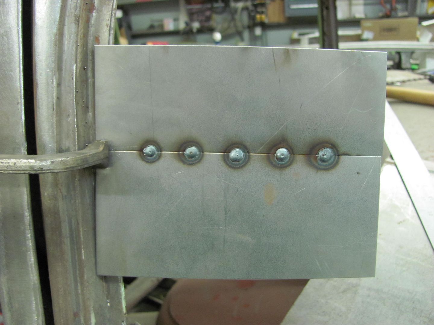
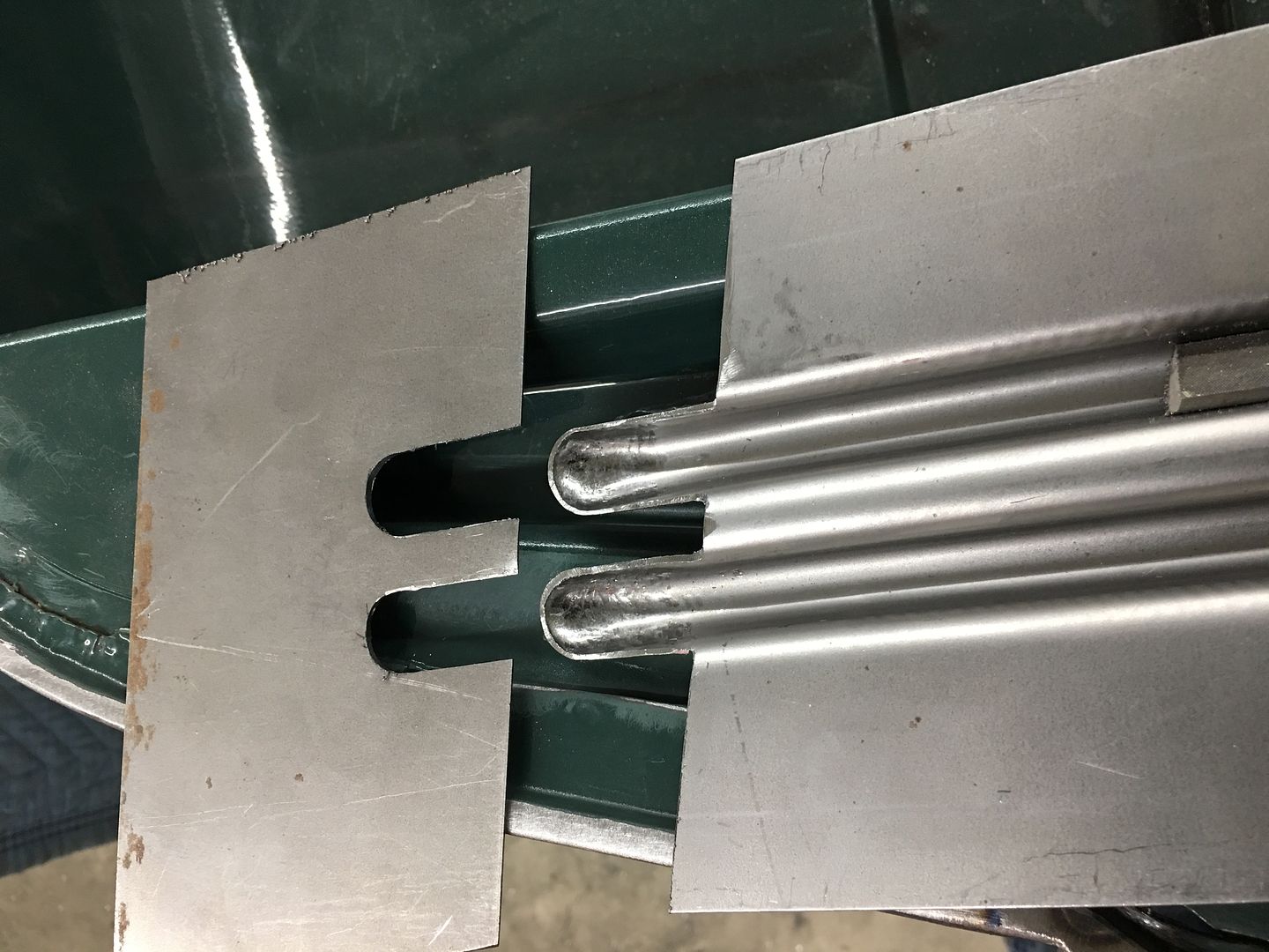
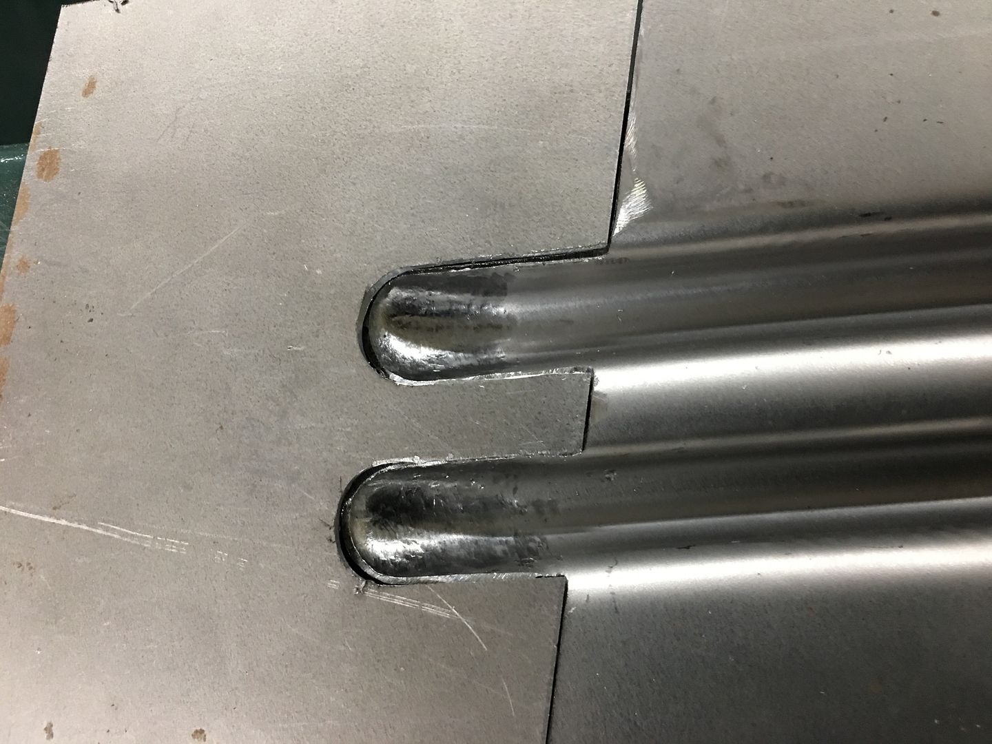
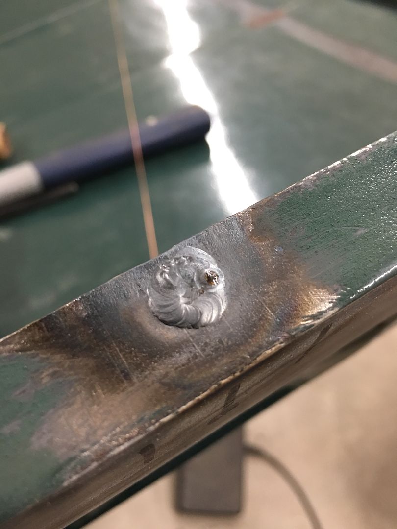
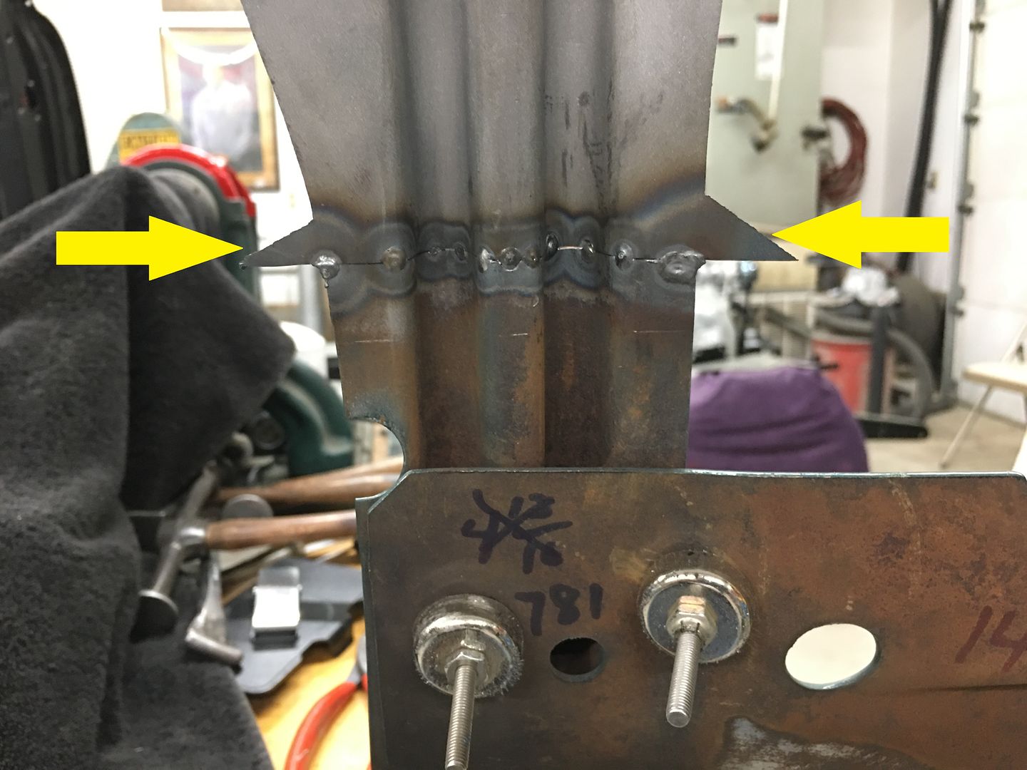
The TIG is used to fully weld the patches in place...
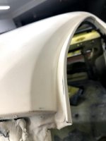

Front side:


IMG_6608.JPG


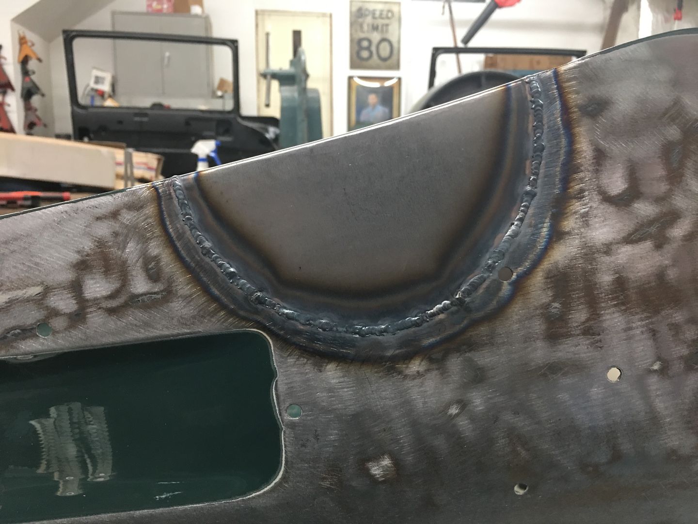
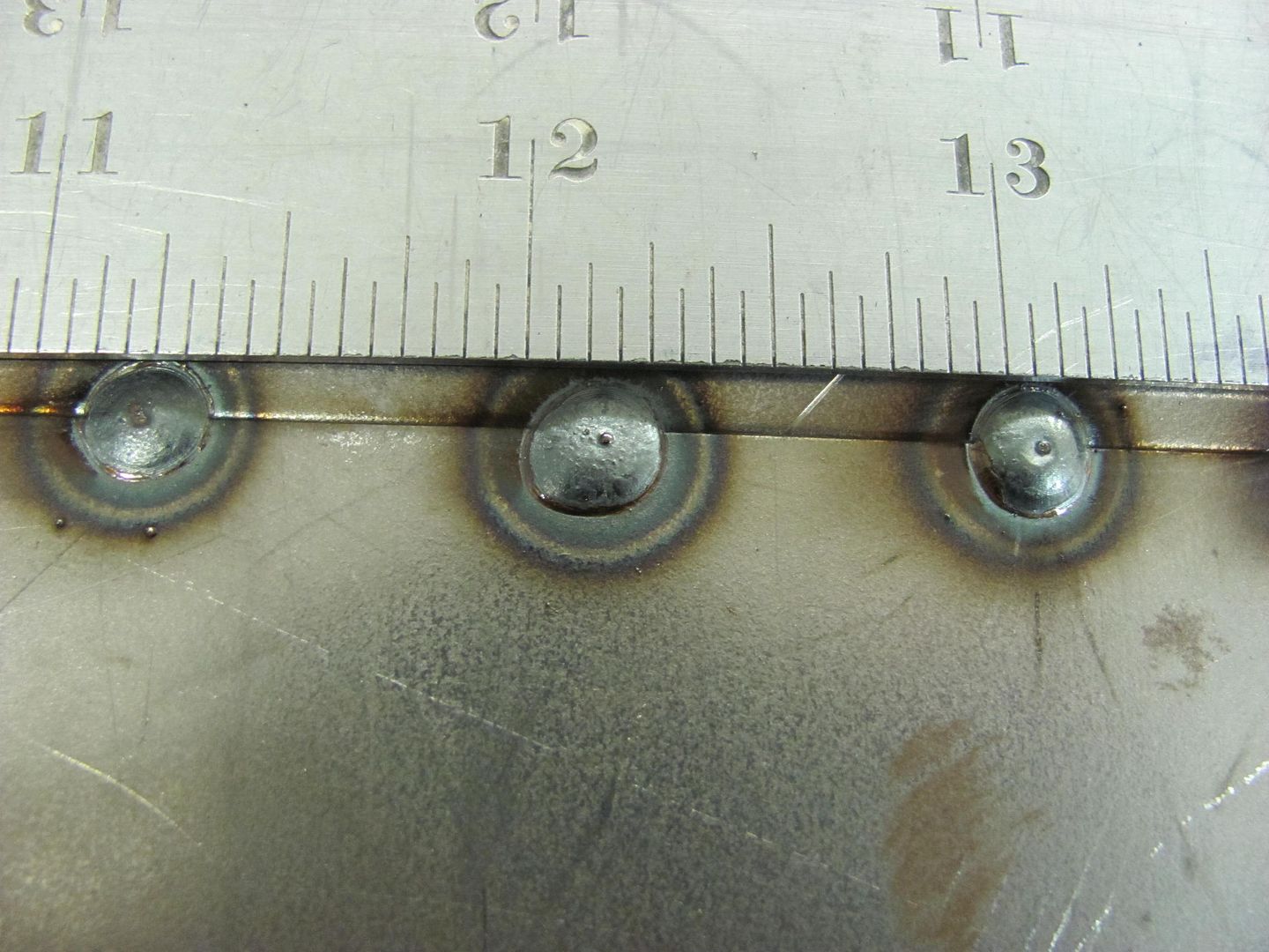
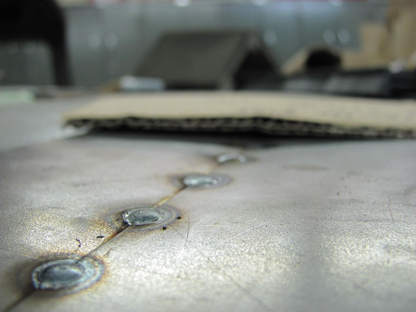
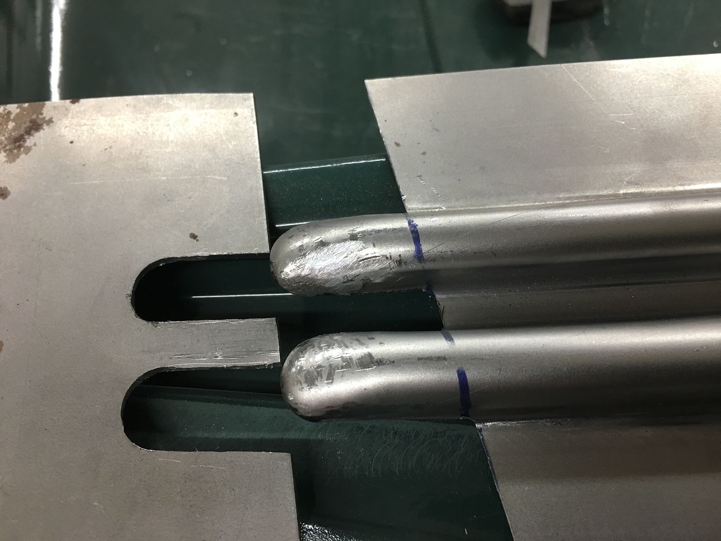
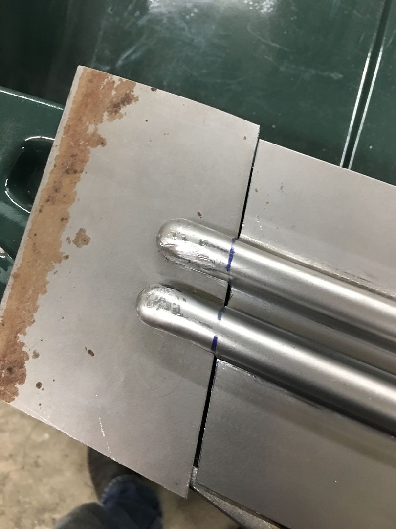
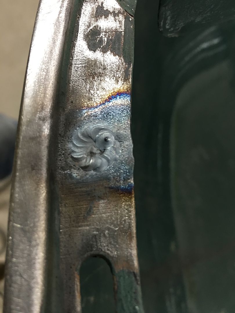
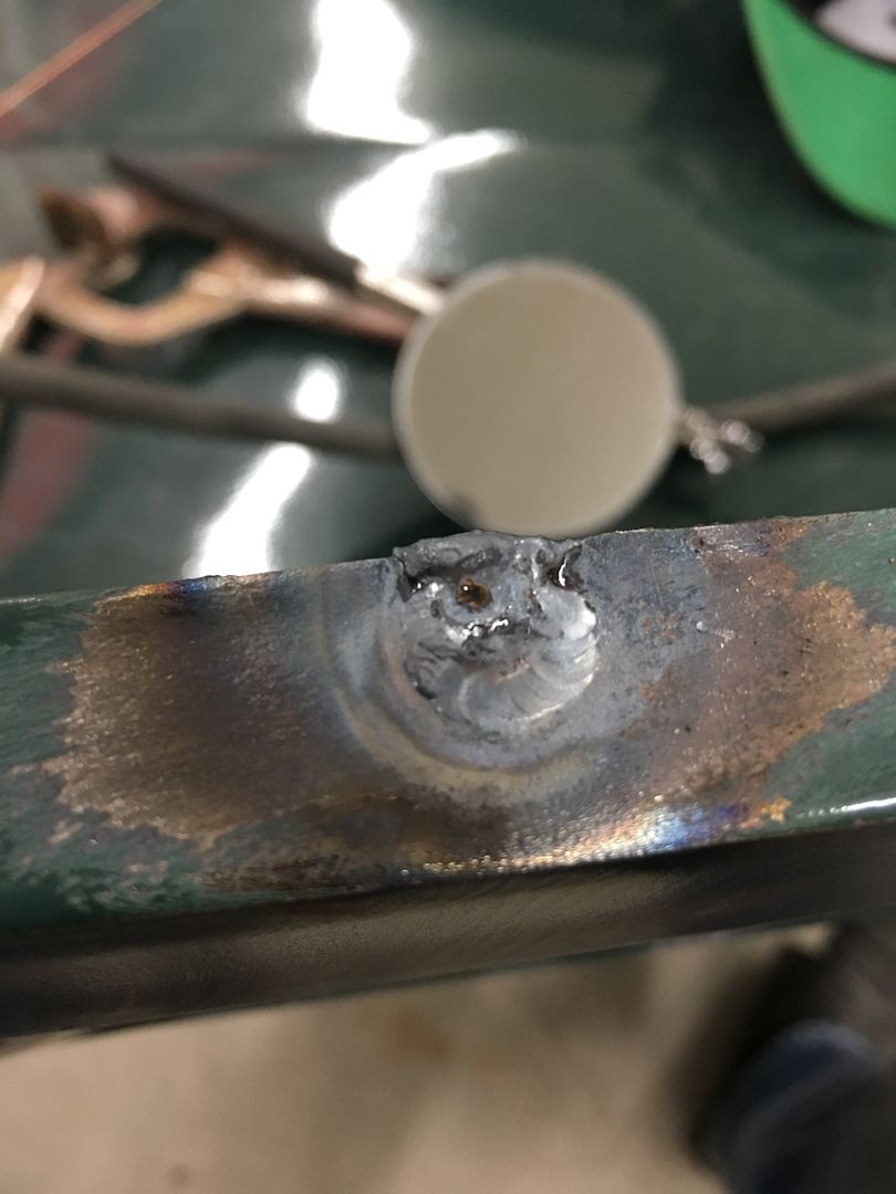
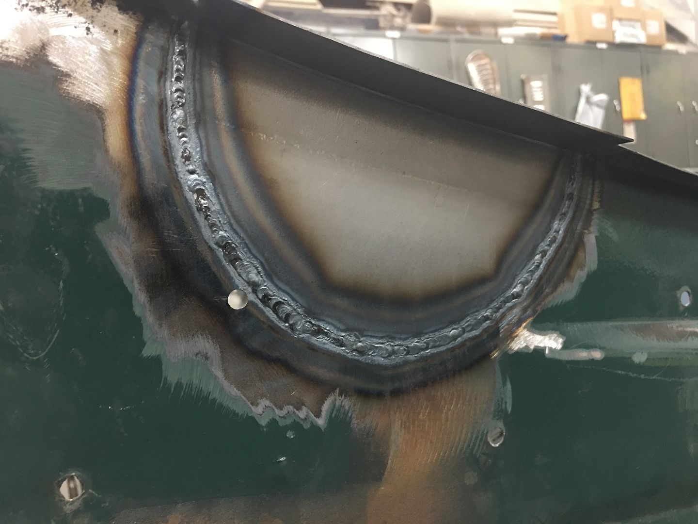
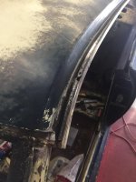
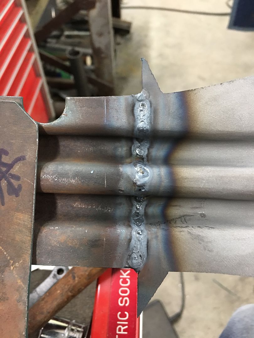
Back side, full penetration on the weld..


IMG_6606.JPG


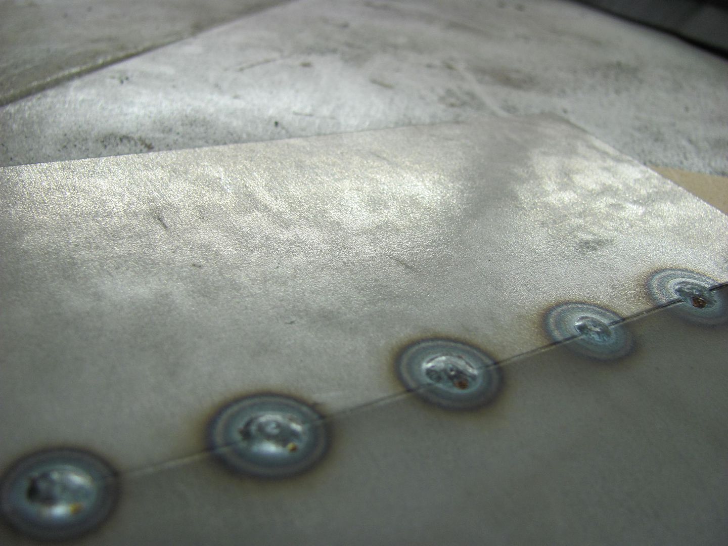
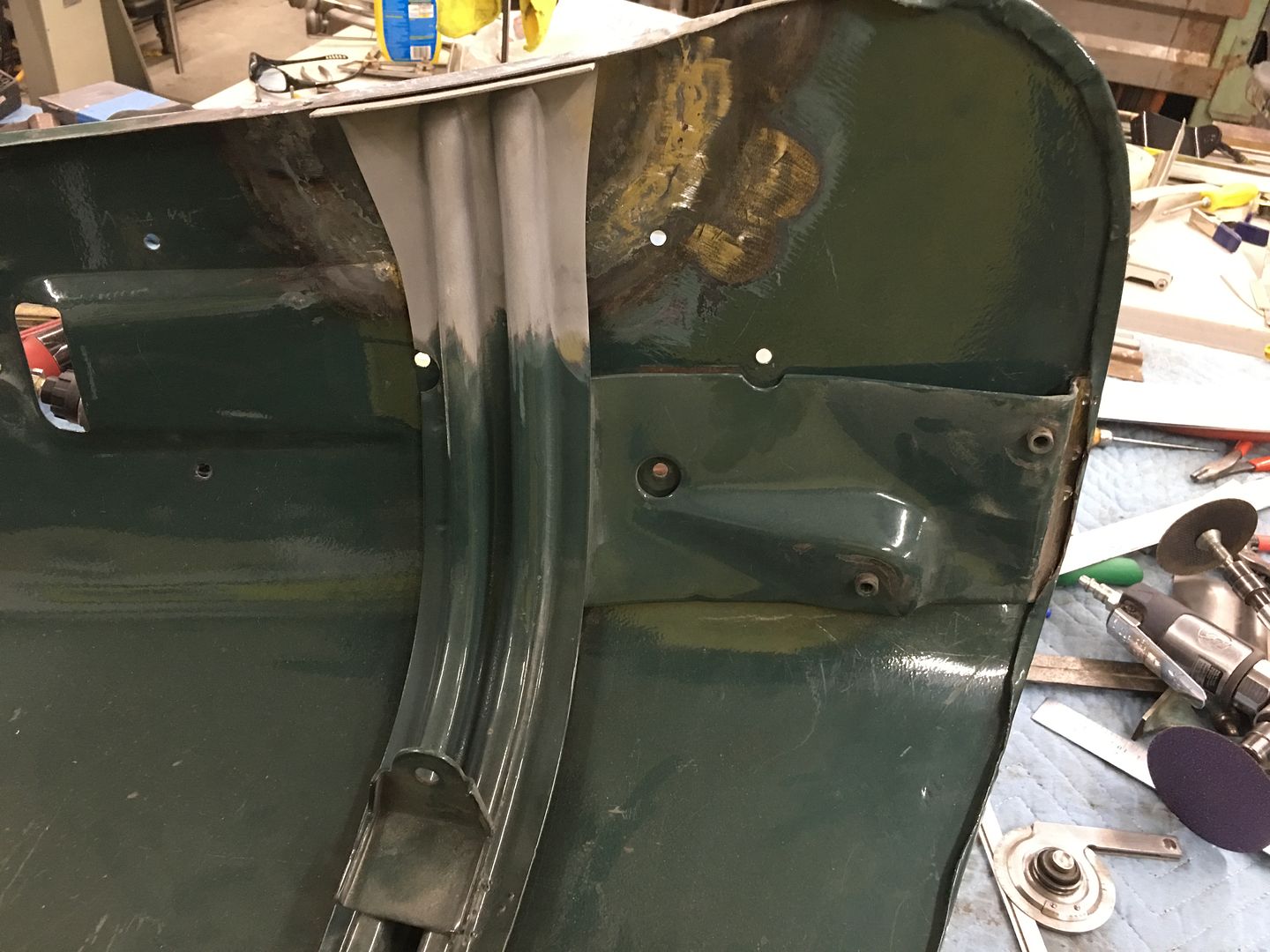
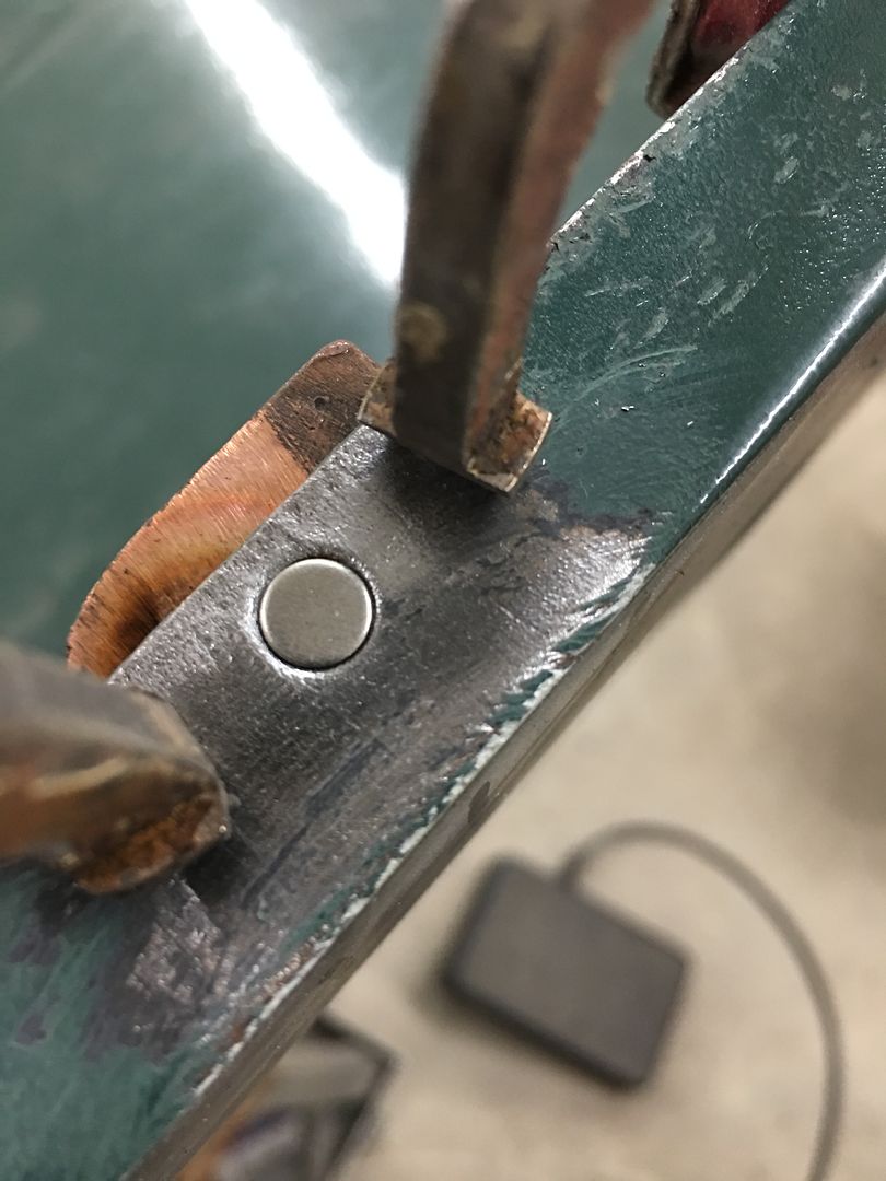
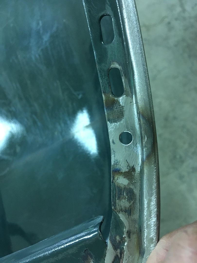
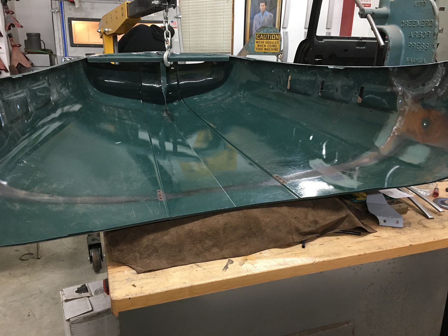
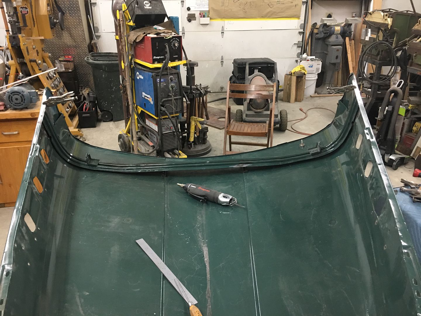
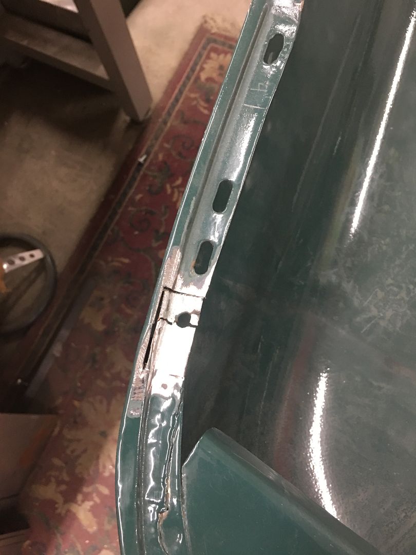
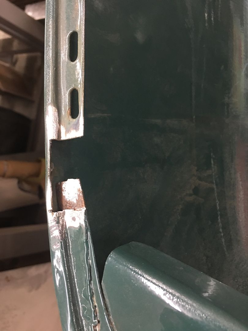
The weld seams are then planished and dressed. Next, the front of the hood had a stress crack adjacent to one of the rubber bumpers. To stabilize the hood prior to cutting out this area, the brace is clamped back in place..


IMG_6616.JPG


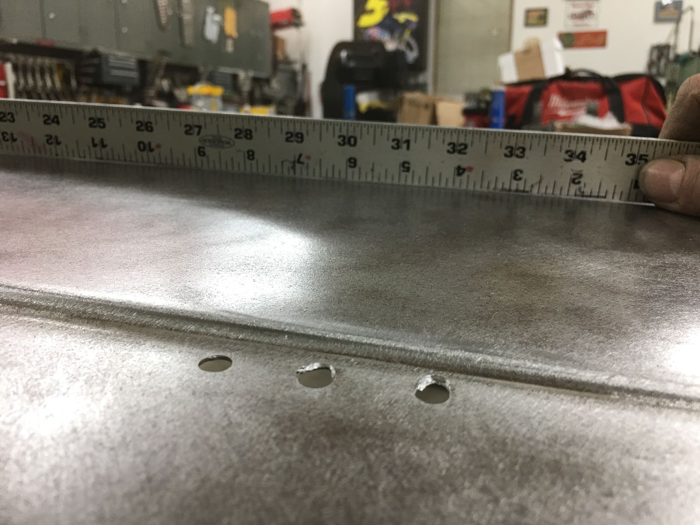
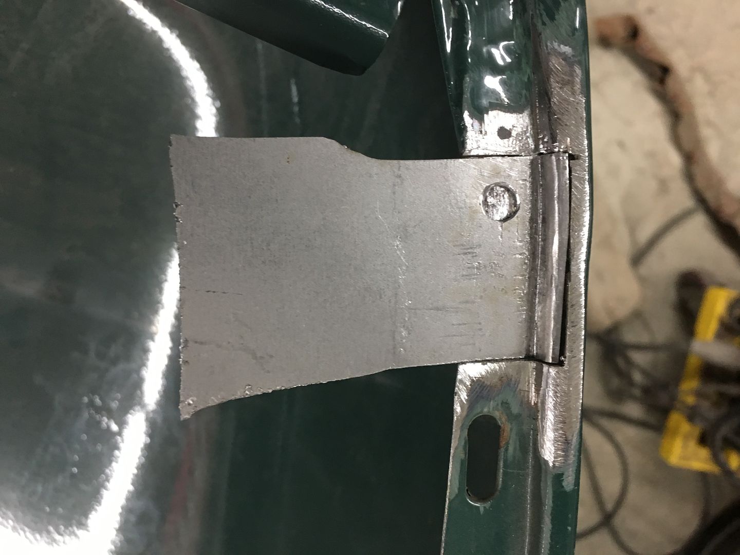
The damaged area is cut out, a "doubler" had been used toward the front to add strength to the area, so care is used to not cut that off..


IMG_6613.JPG


IMG_6614.JPG


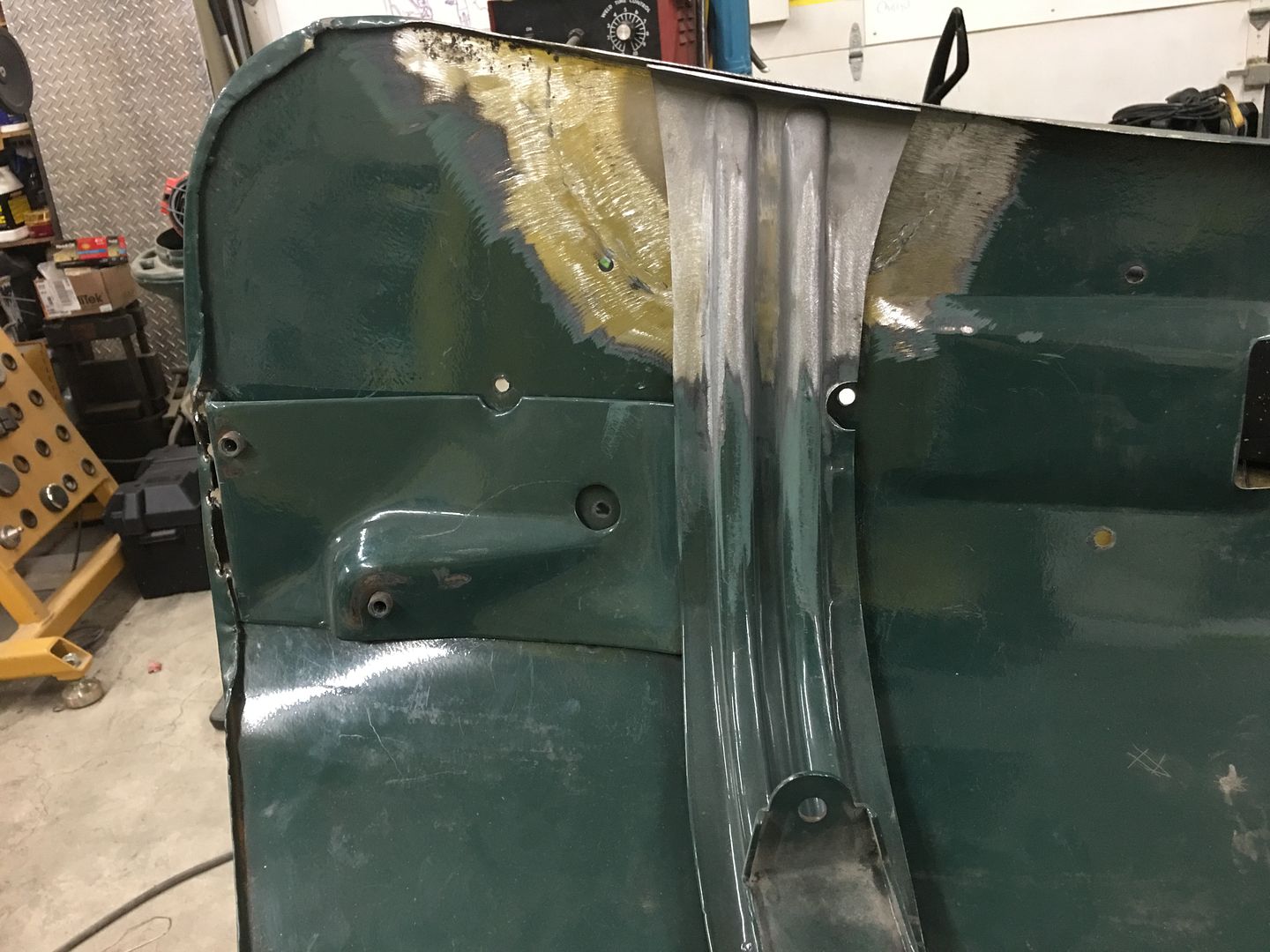
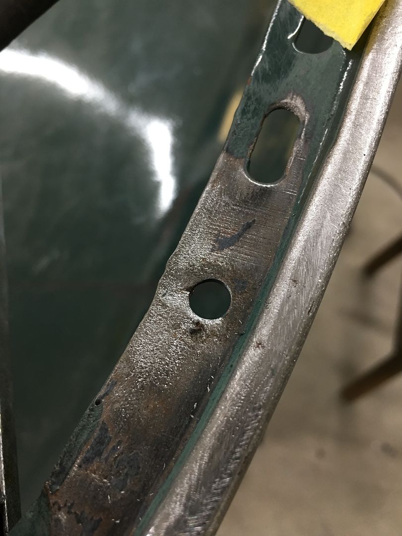
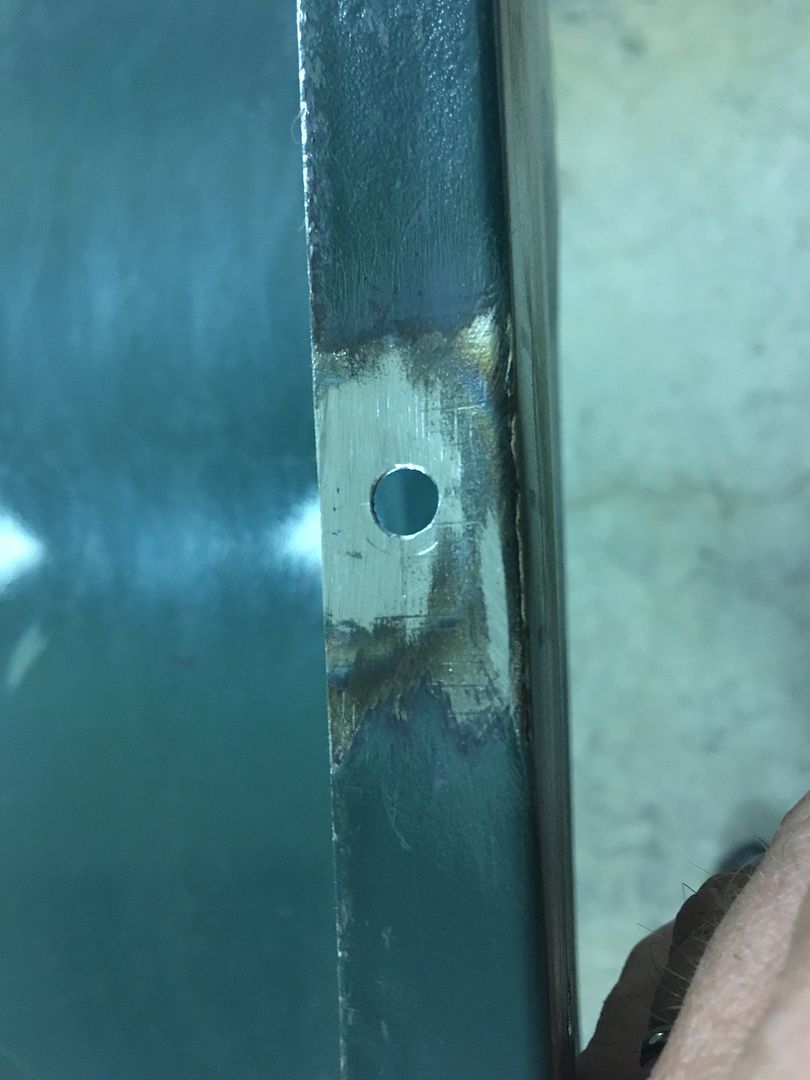
A replacement patch is cut out, bends added, and tacked in place. A plug weld ties this in with the doubler..


IMG_6623.JPG


IMG_6625.JPG


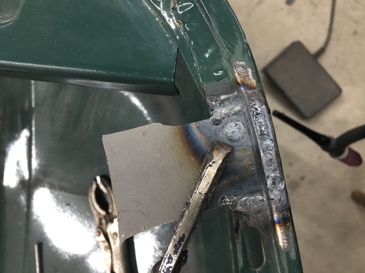
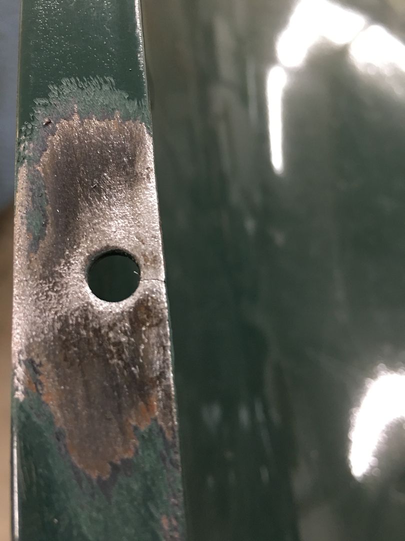
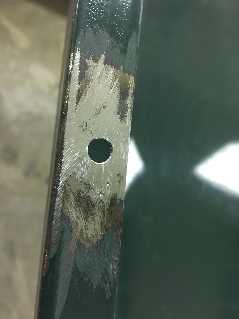
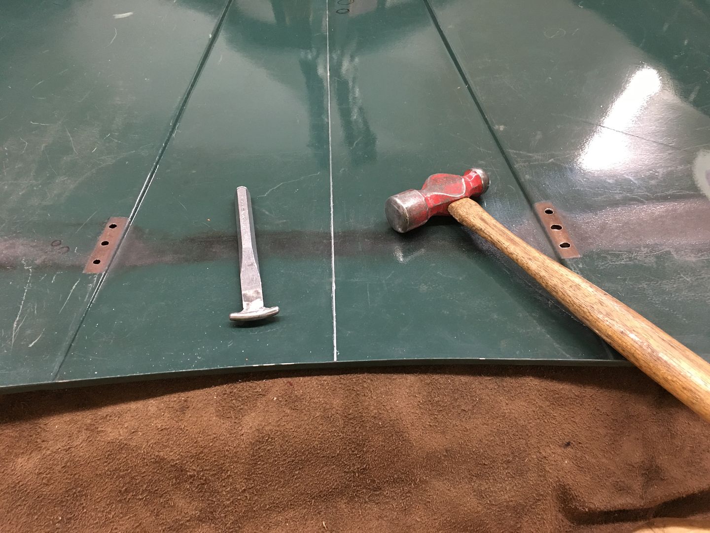
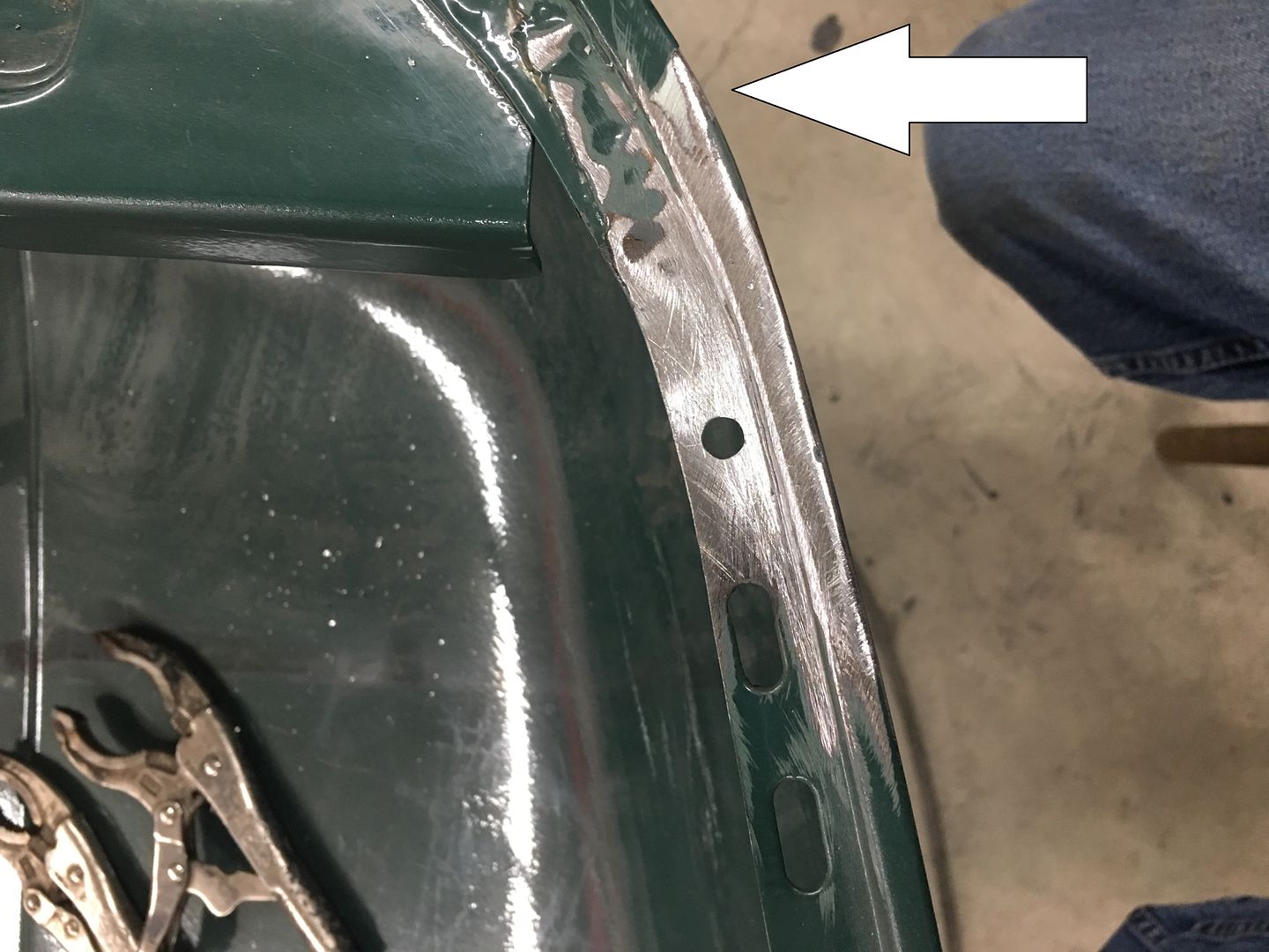
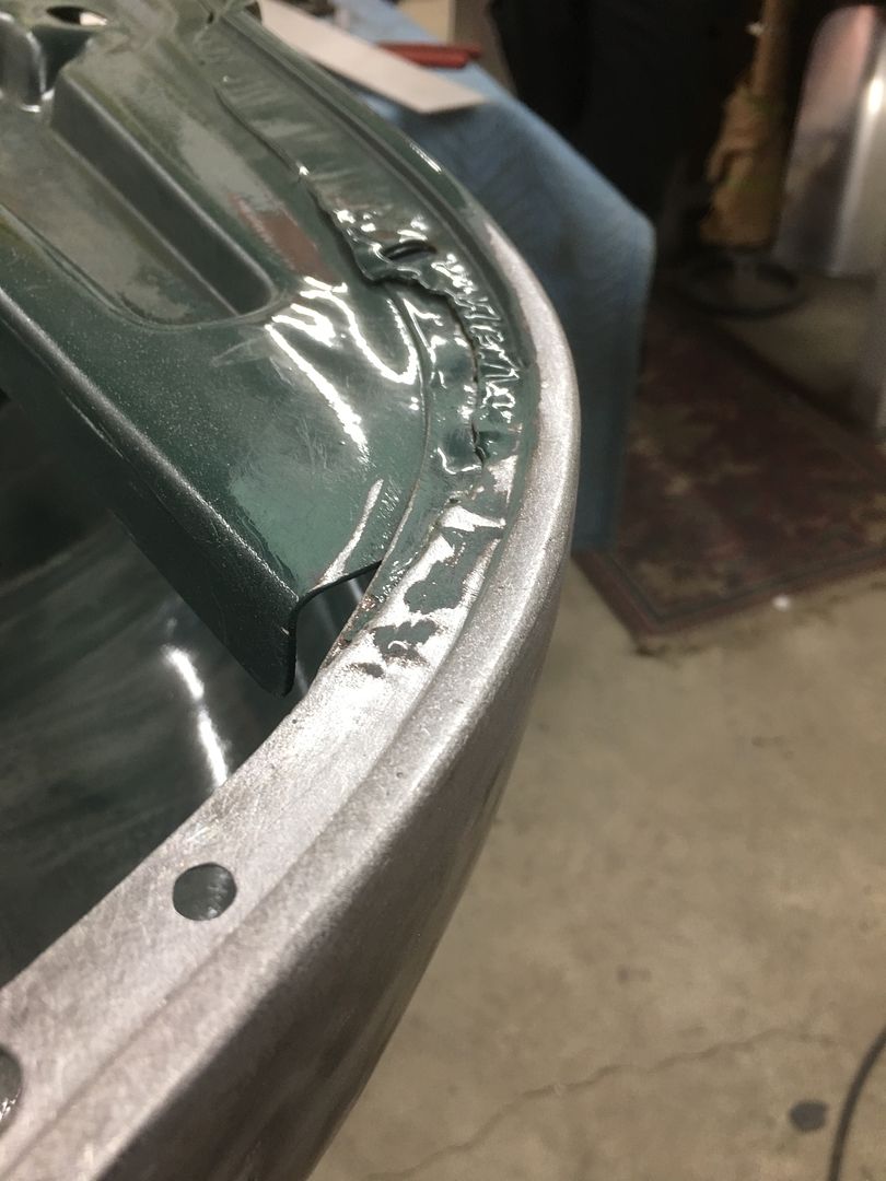
All trimmed and welds dressed, the hood bumper hole is re-drilled in the new patch. Then we notice a bit of filler closer to the nose of the hood (arrow). Let's remove that while we're here to see what carnage lies in wait.


IMG_6627.JPG


Gotta love this game of dominos..


IMG_6632.JPG


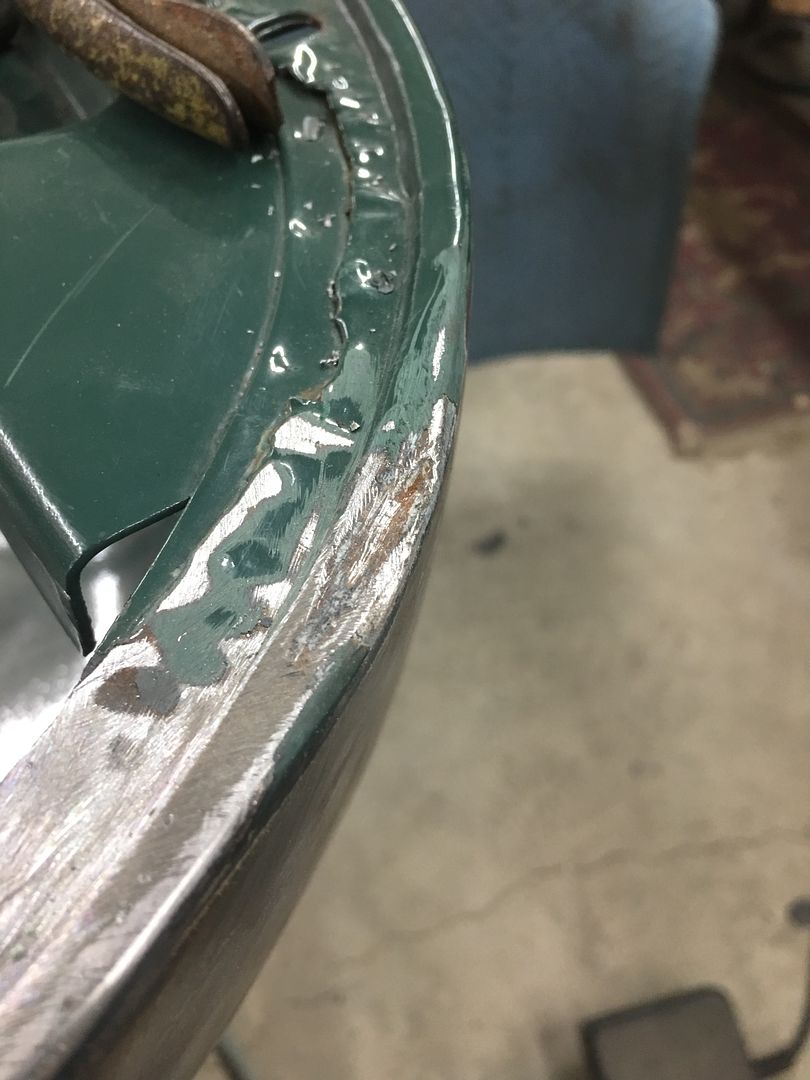
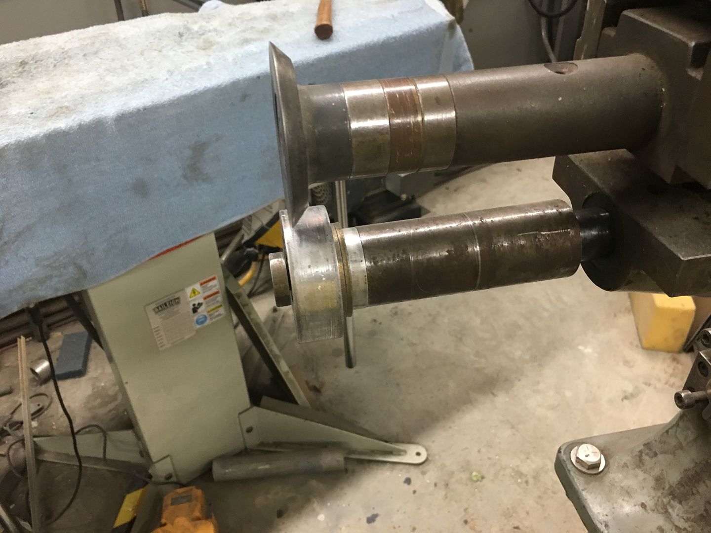
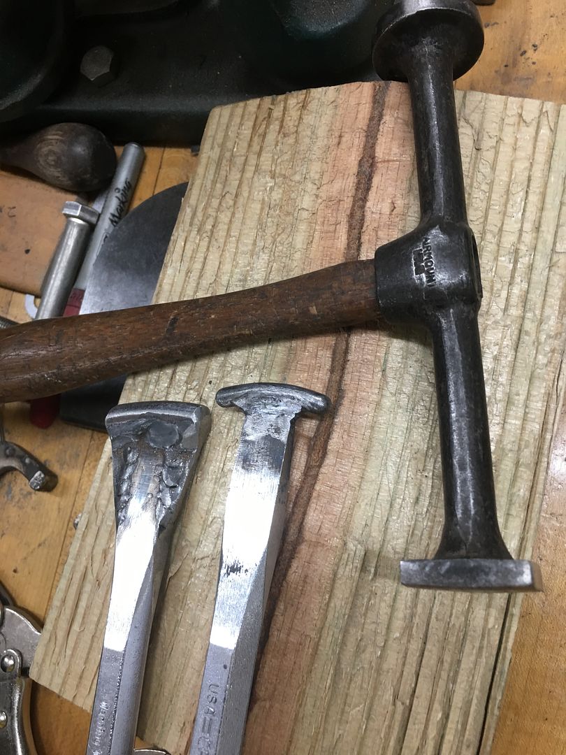
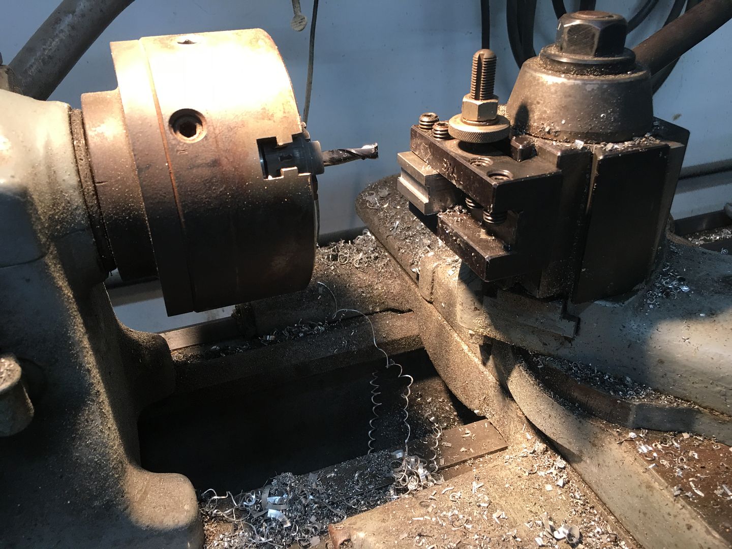
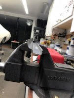
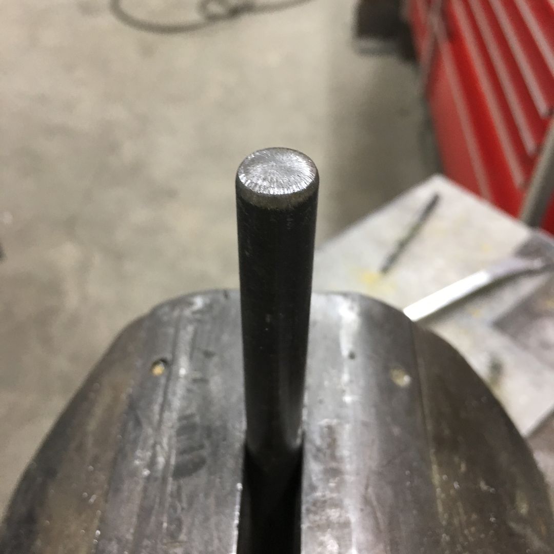
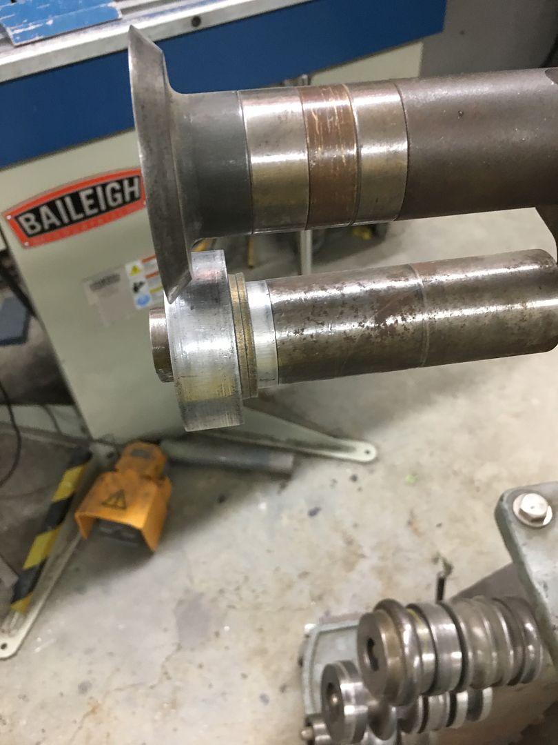
The low area needs to be bumped up, and with little room for swinging hammers, a new tool is in order. Using the South Bend "milling machine" a die is made for the outer portion..


IMG_6628.JPG


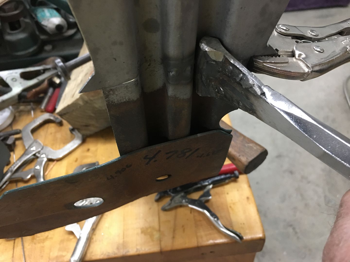
Using a pair of C-clamp vise grips (there goes another pair) the die we made will be welded to one side, the opposite is giving a bit of a trim to better fit in the confines of the slight gap available on the inside..


IMG_6633.JPG


IMG_6634.JPG


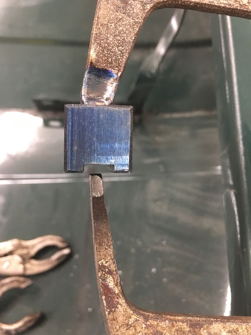
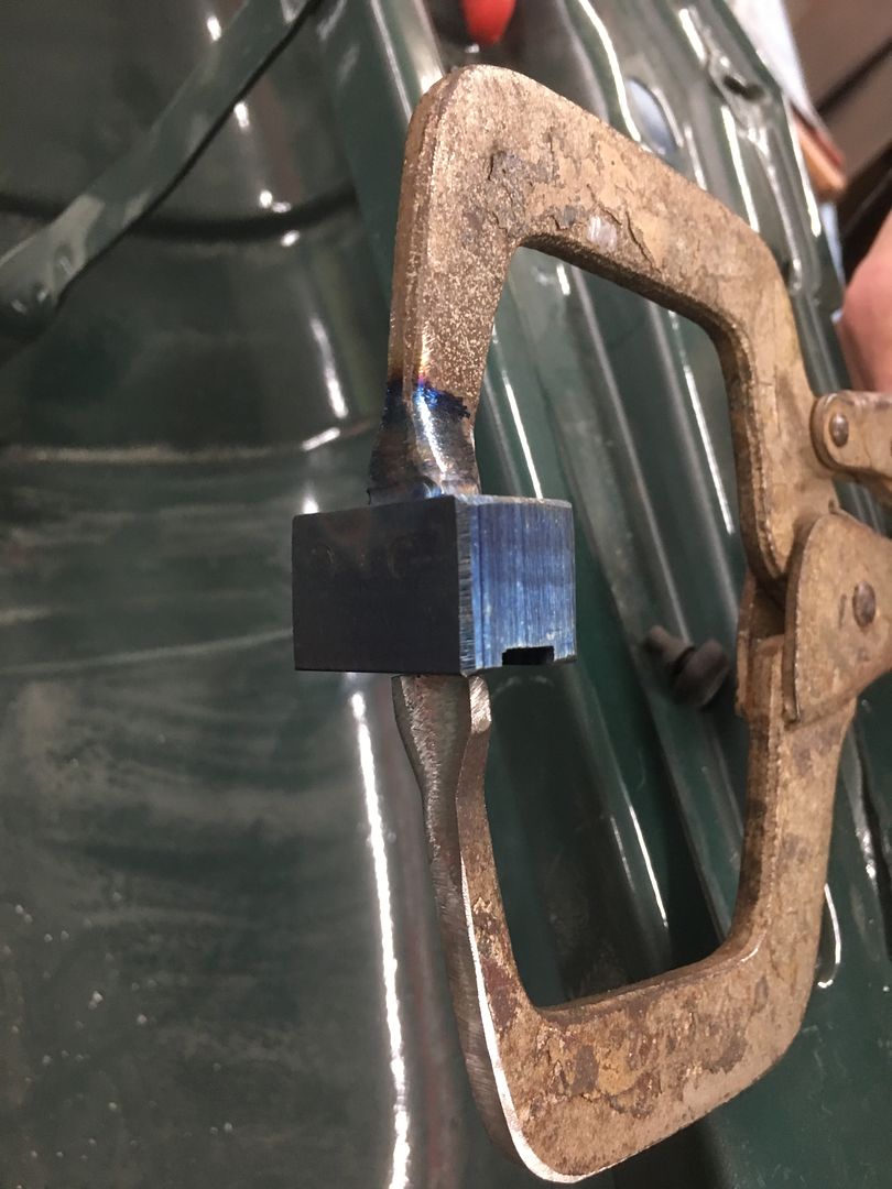
I missed the action shots, but the clamping of the vise grip is used to raise the low areas. Then dressed out for a much better "filler free" lower edge for the hood.


IMG_6637.JPG


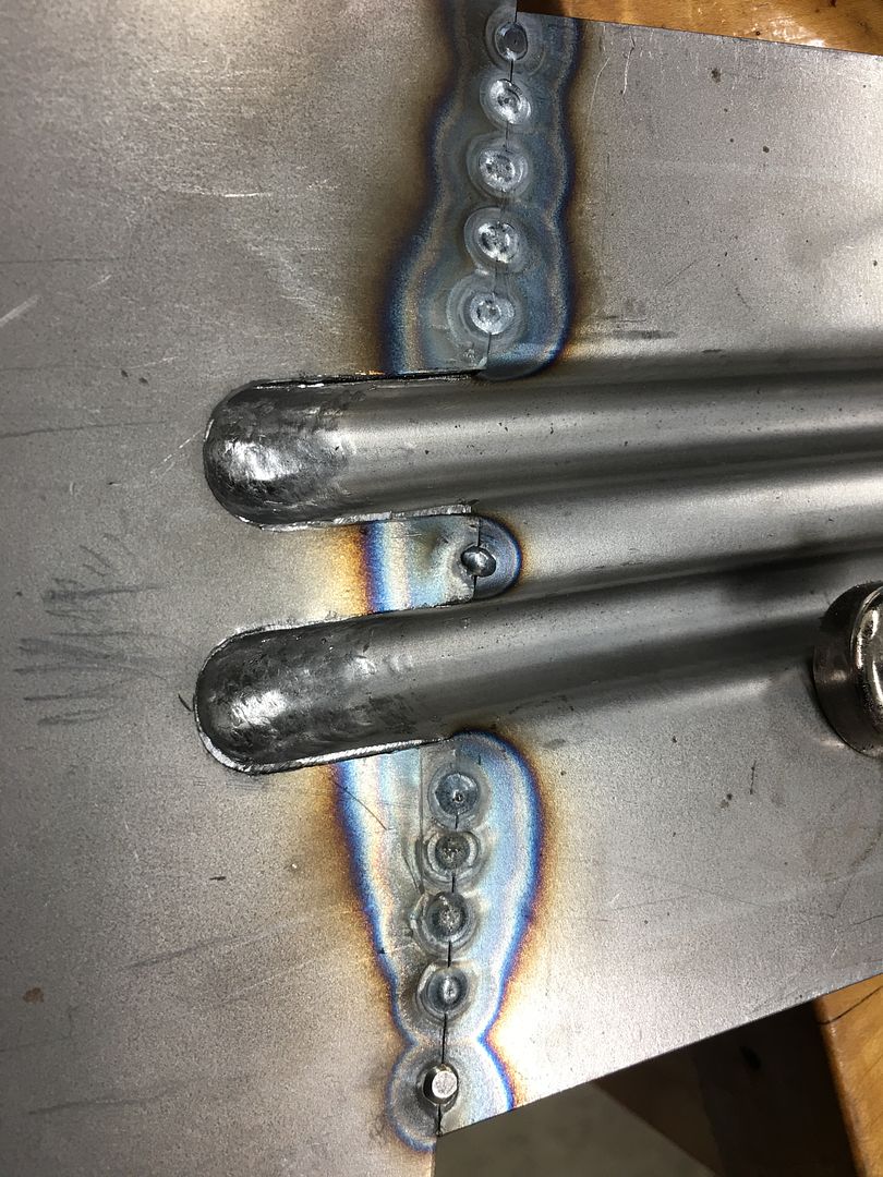
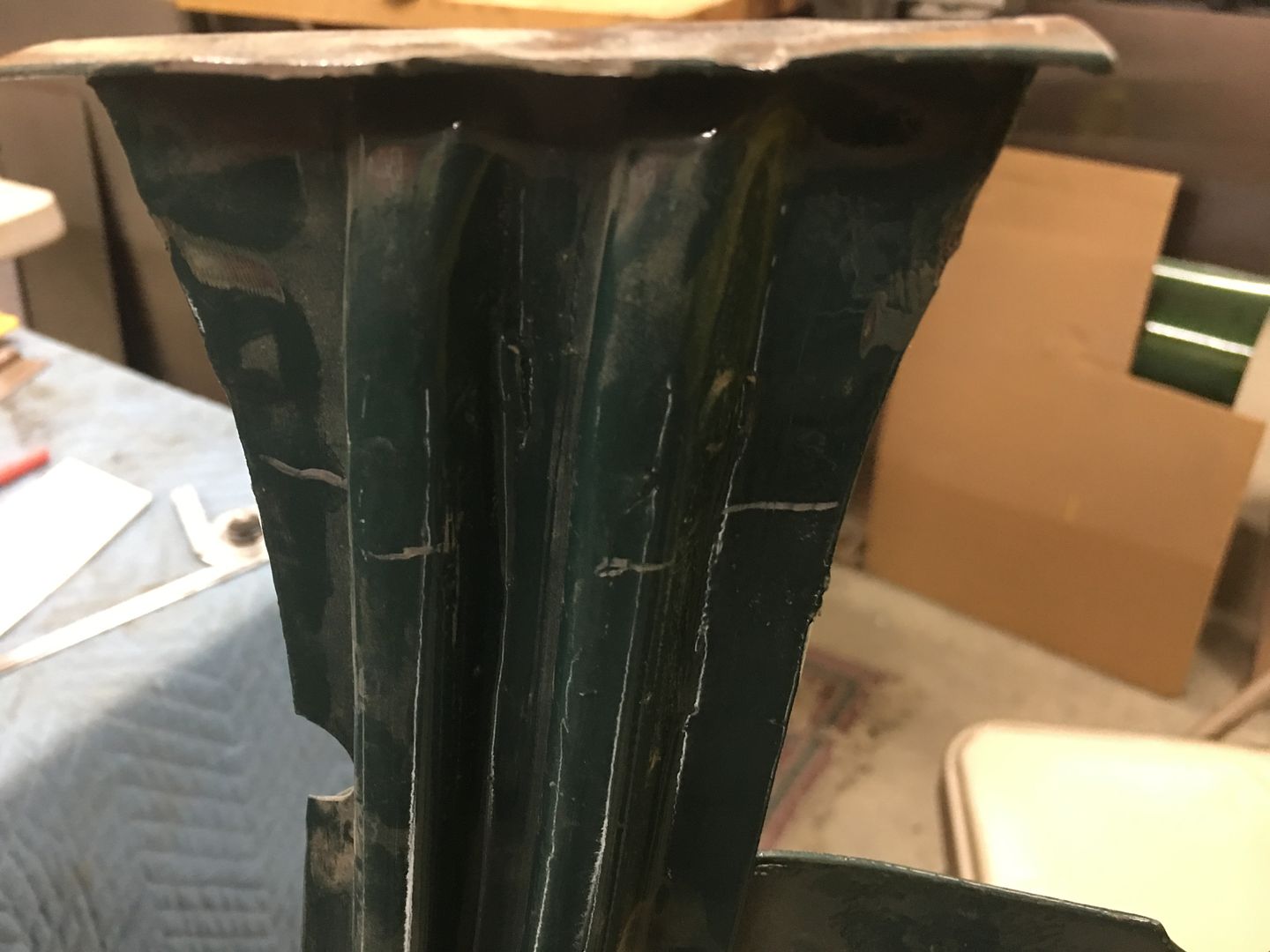
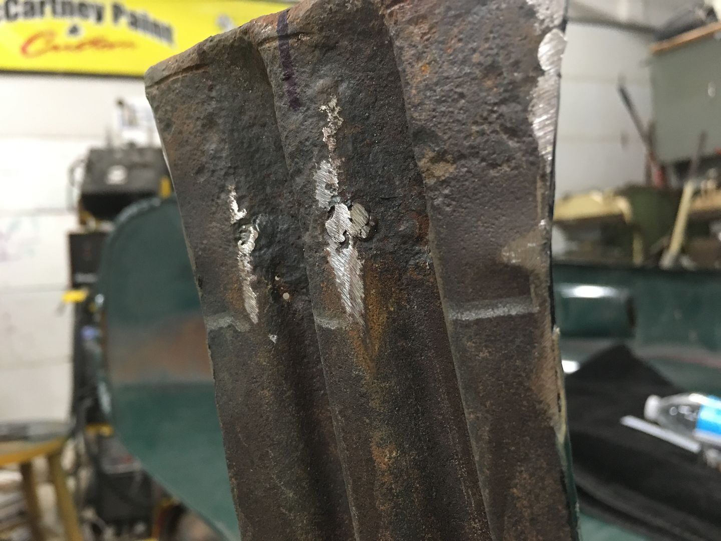
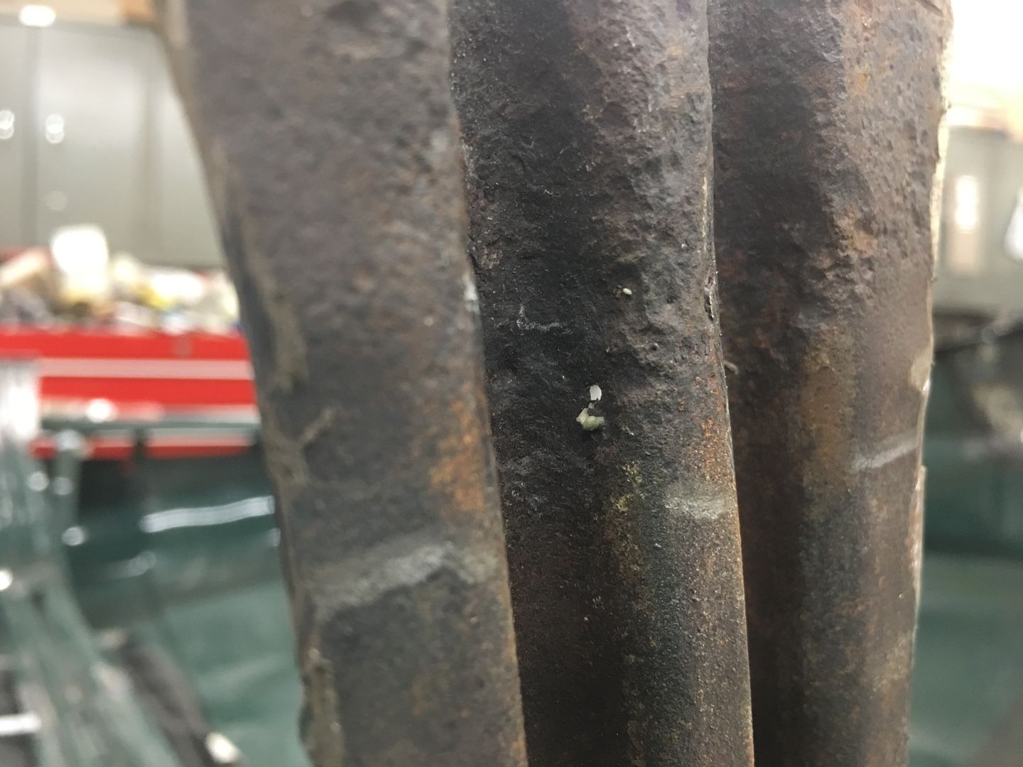
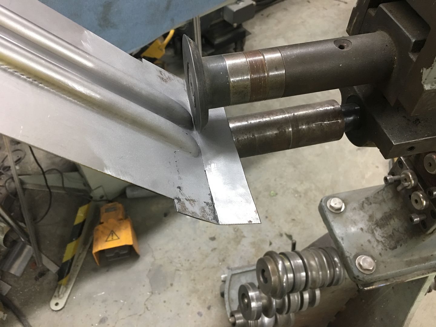
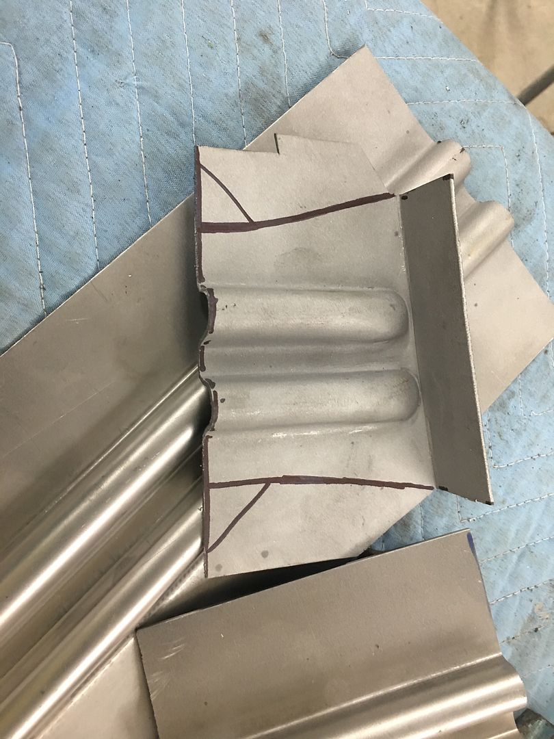
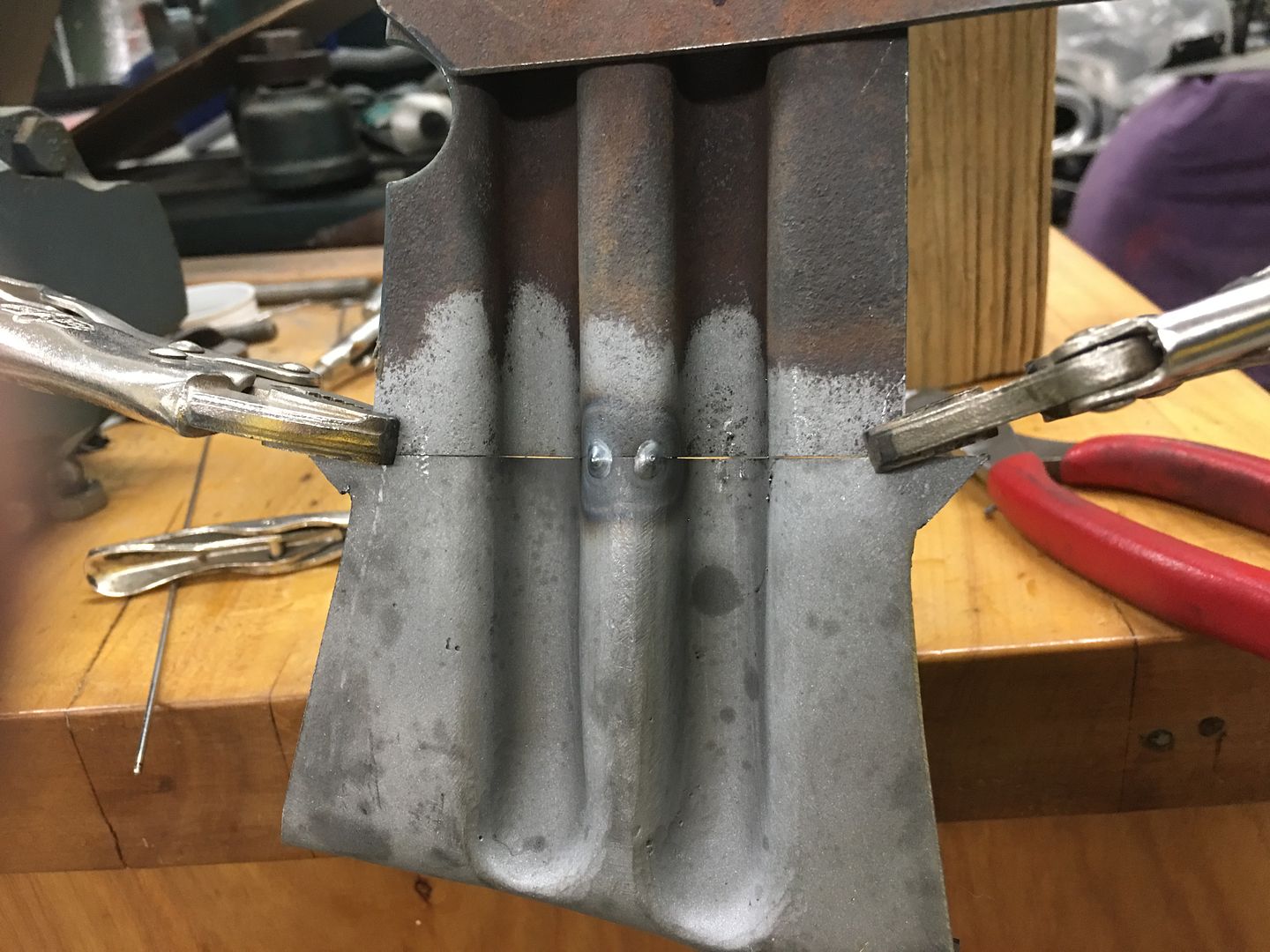
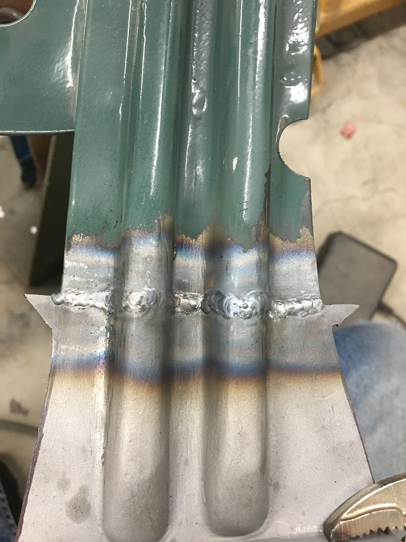
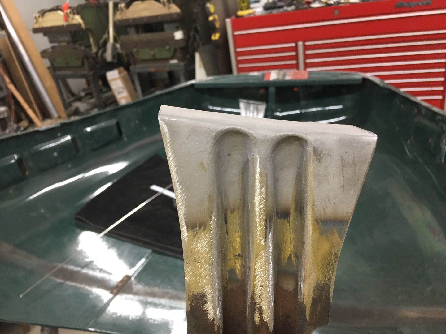
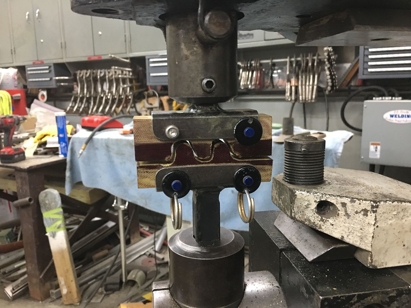
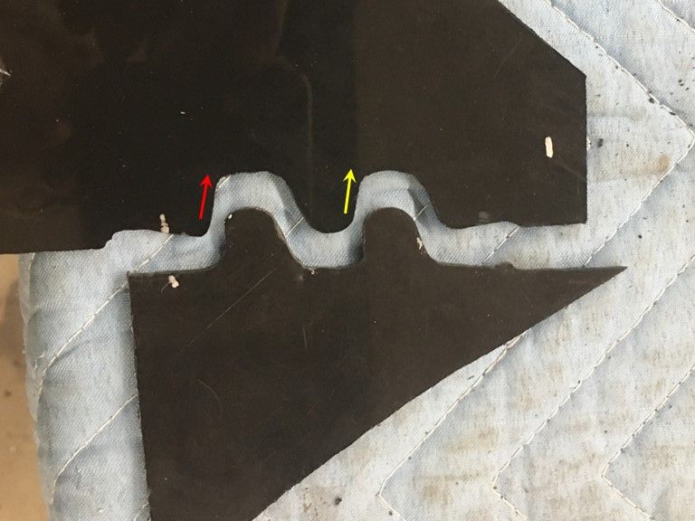
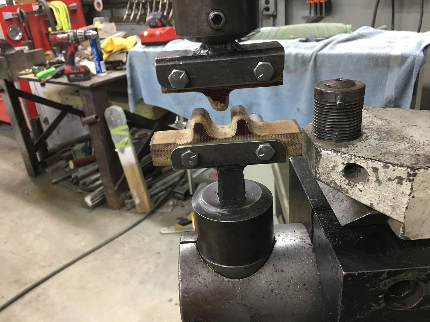
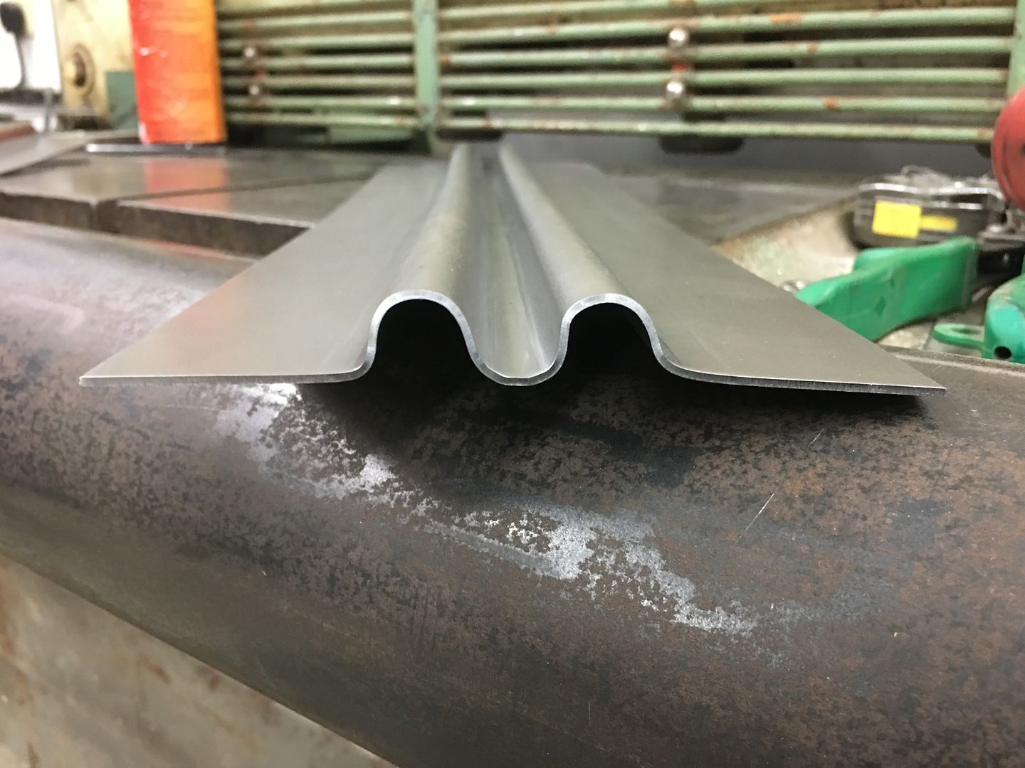
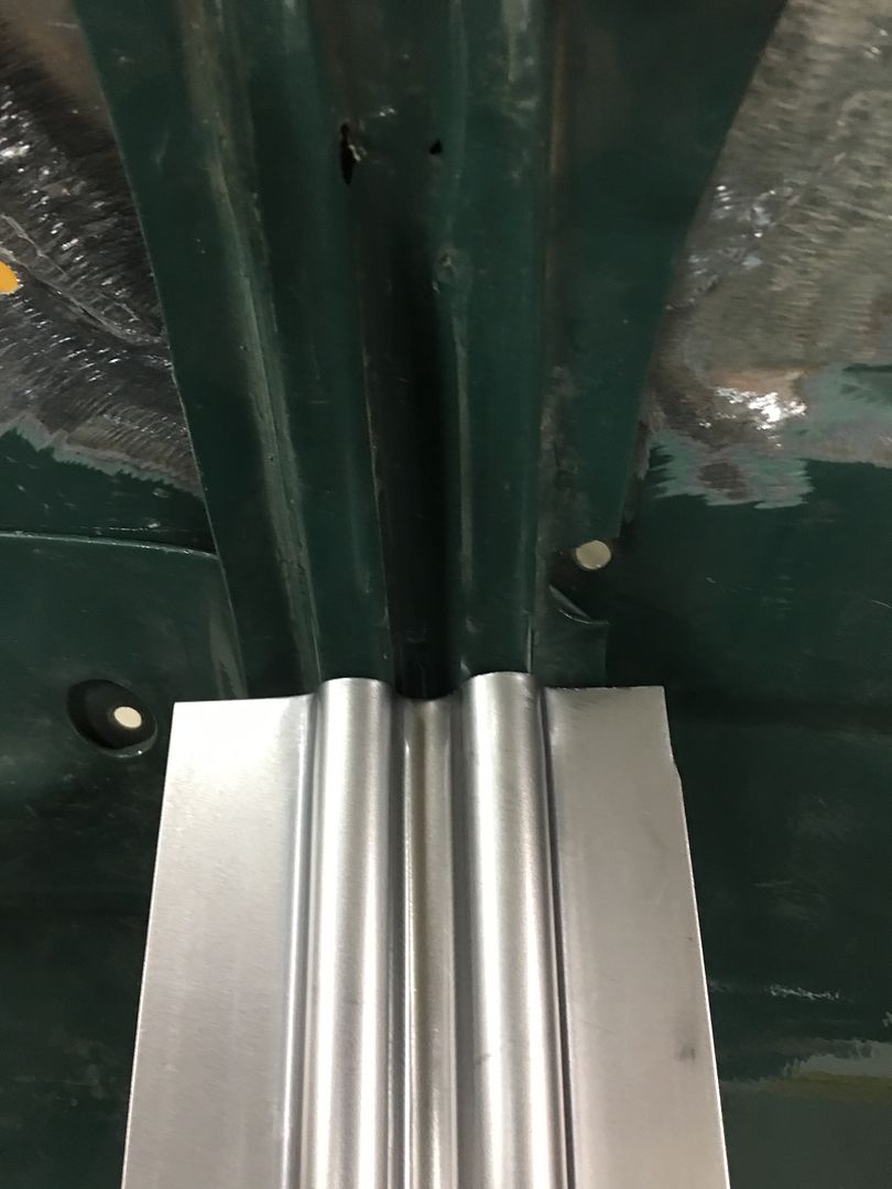
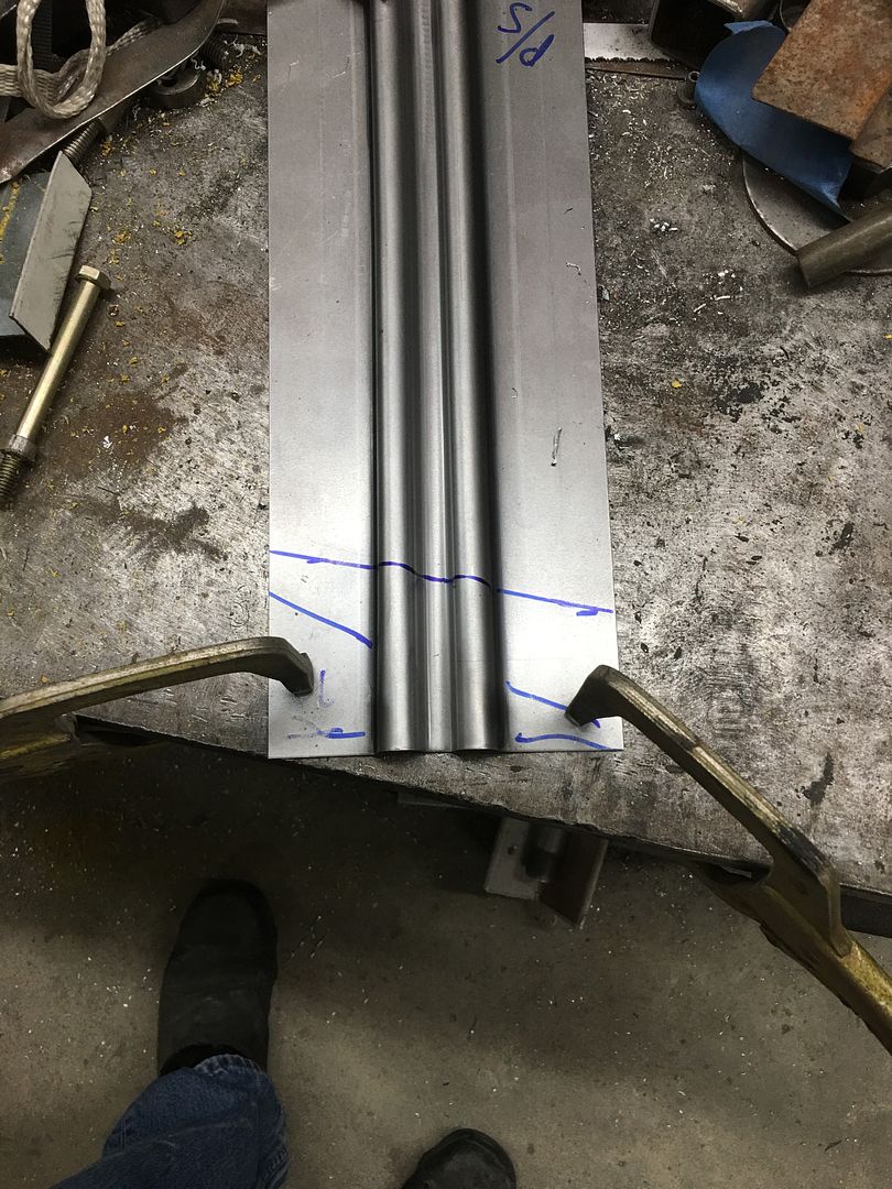
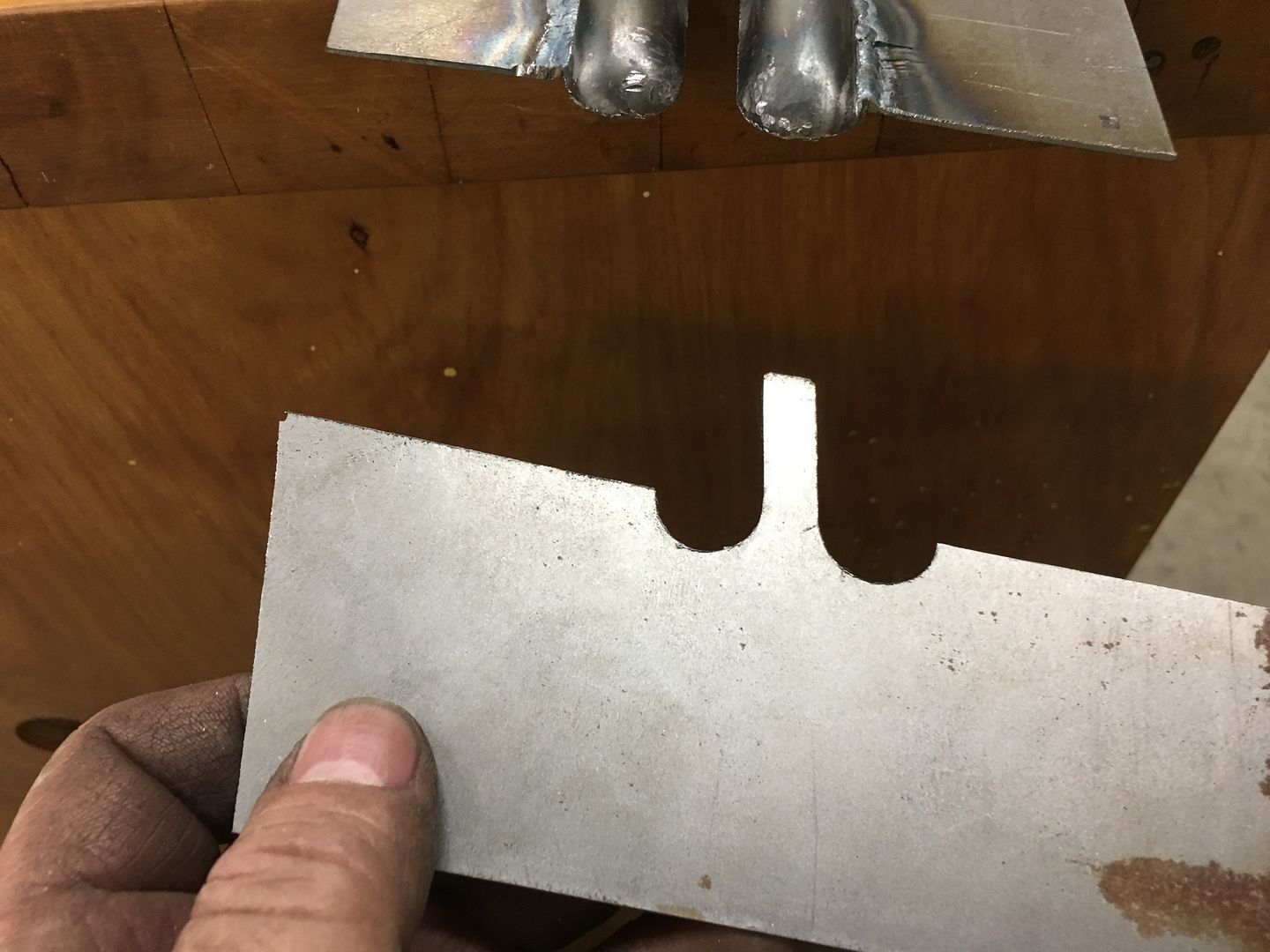
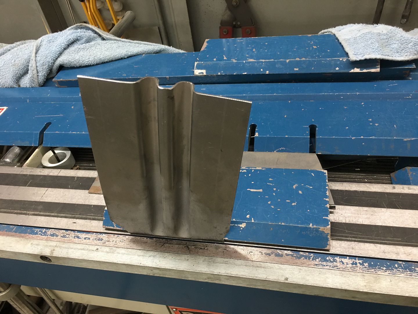
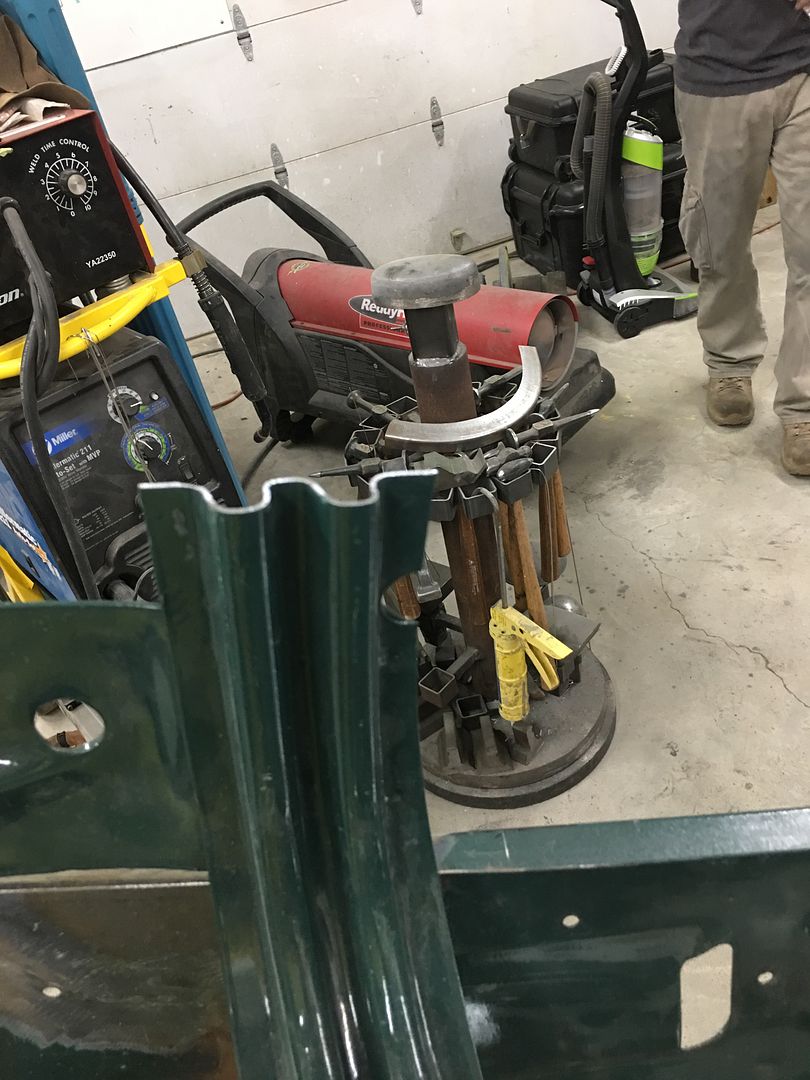
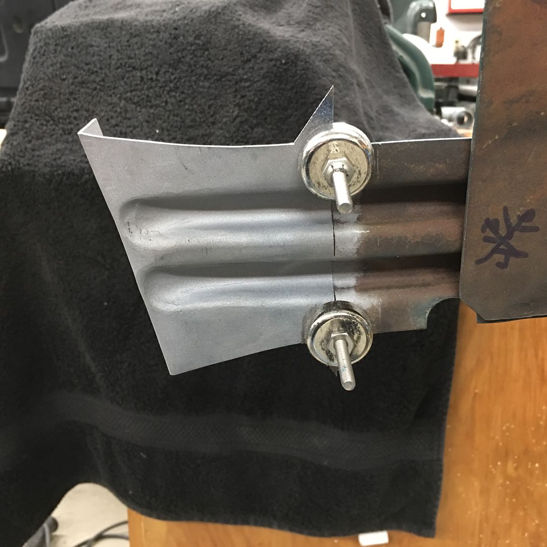
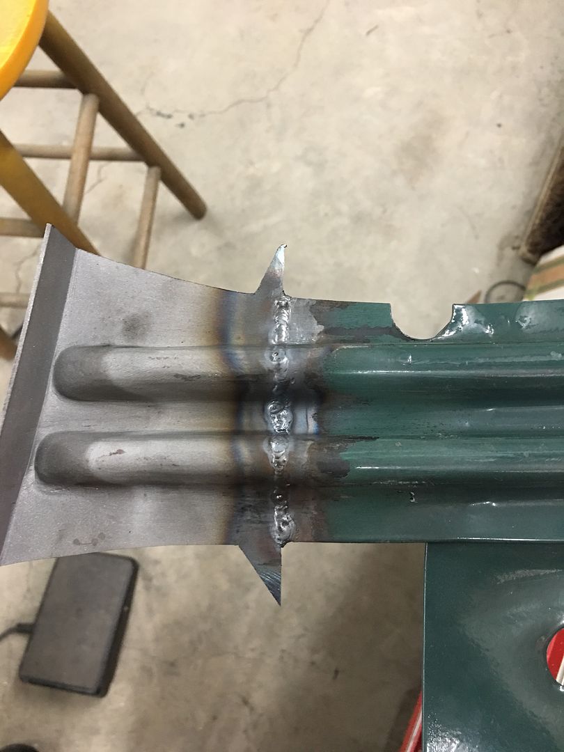
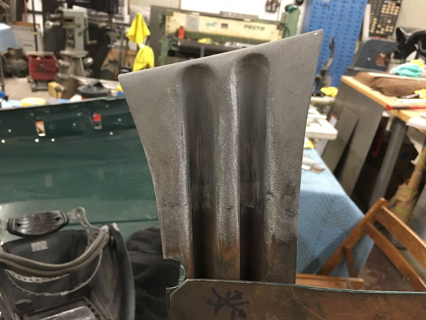
With Mike having completed the dies to duplicate the ribs in the hood brace we did a test run on a piece of 16 Ga cold rolled steel. First upper die addresses middle rib only, way to much drawing going on to expect this out of one set of dies...


IMG_6638.JPG


IMG_6640.JPG


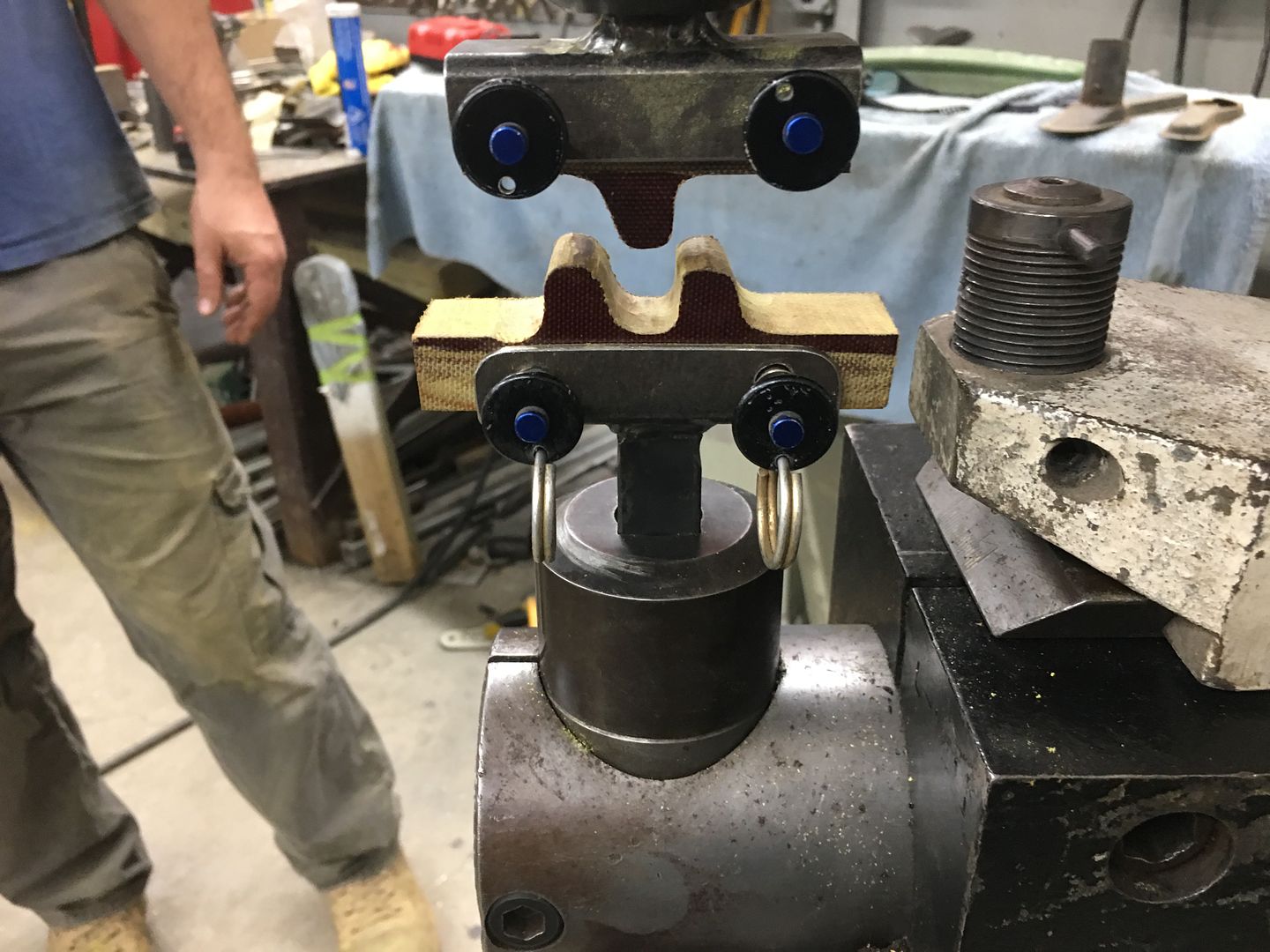
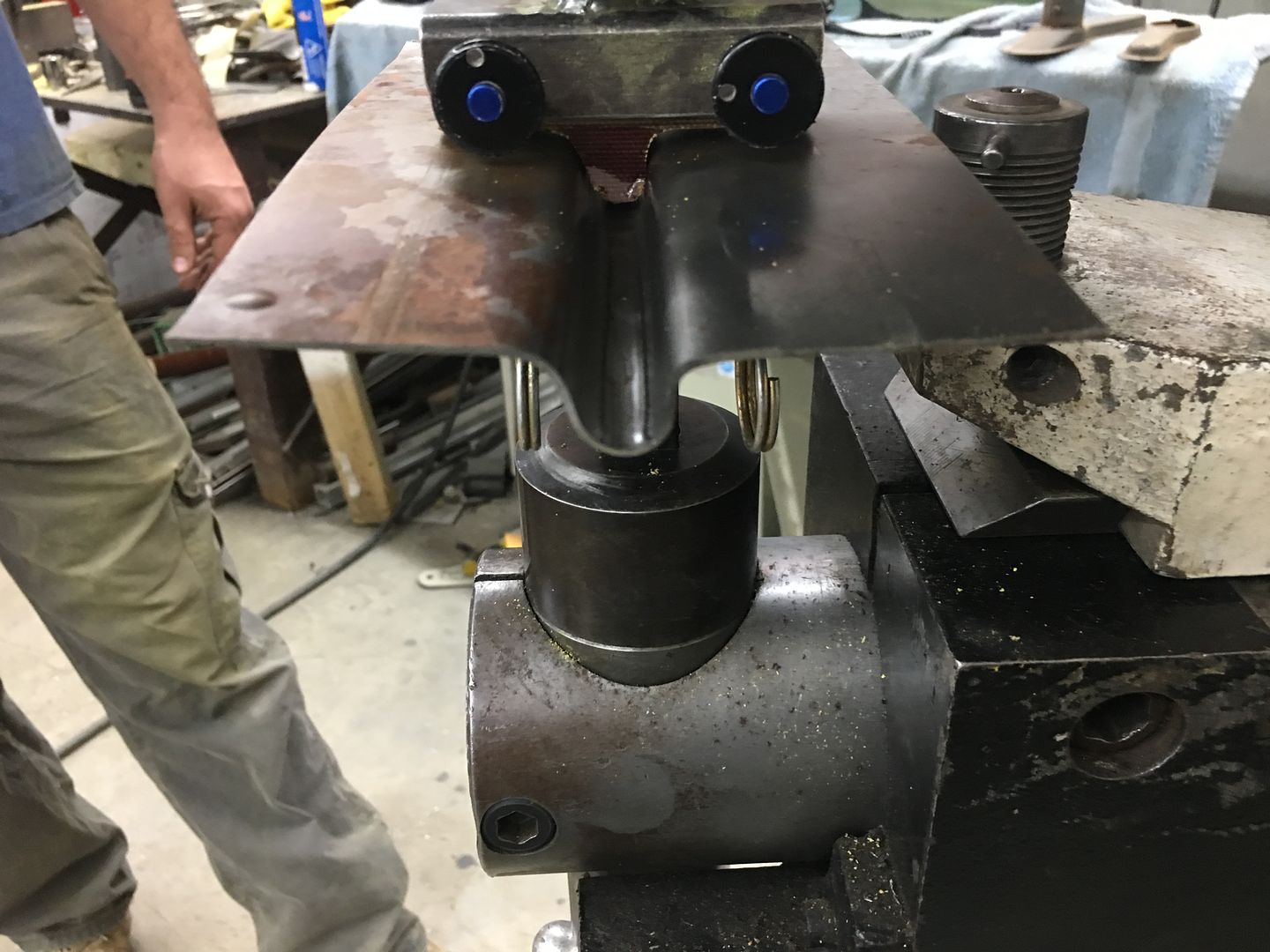
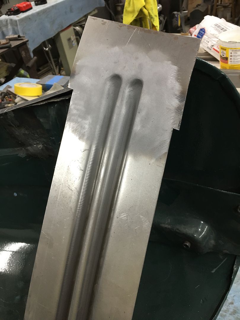
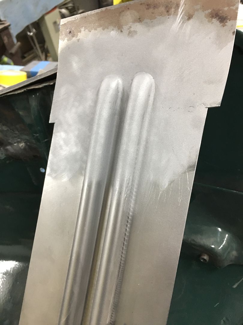
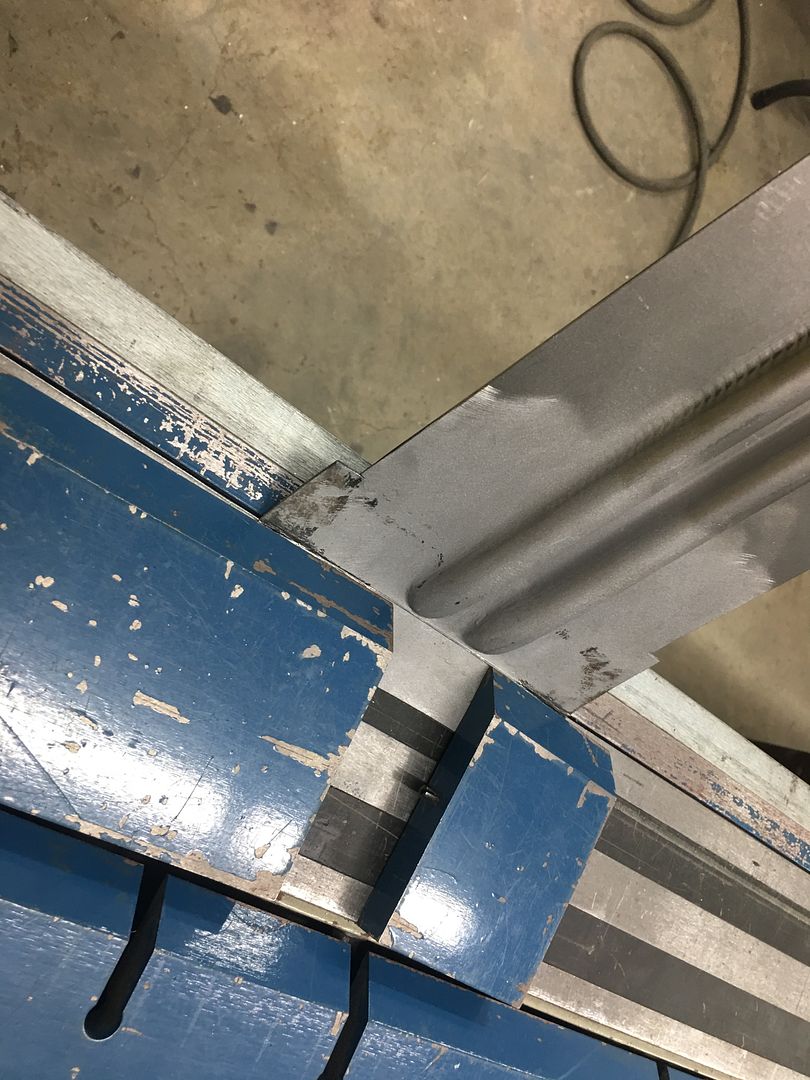
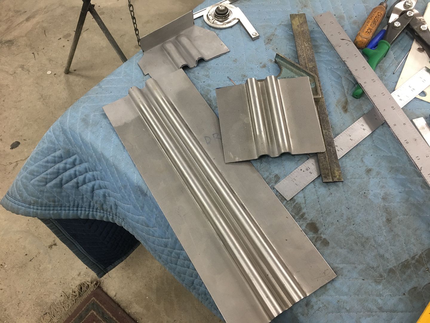
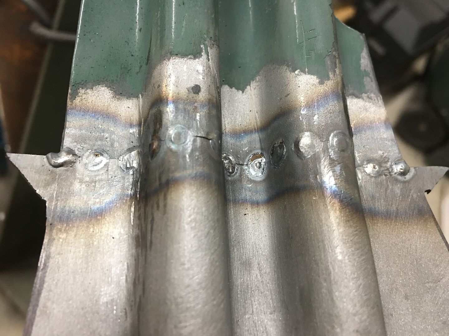
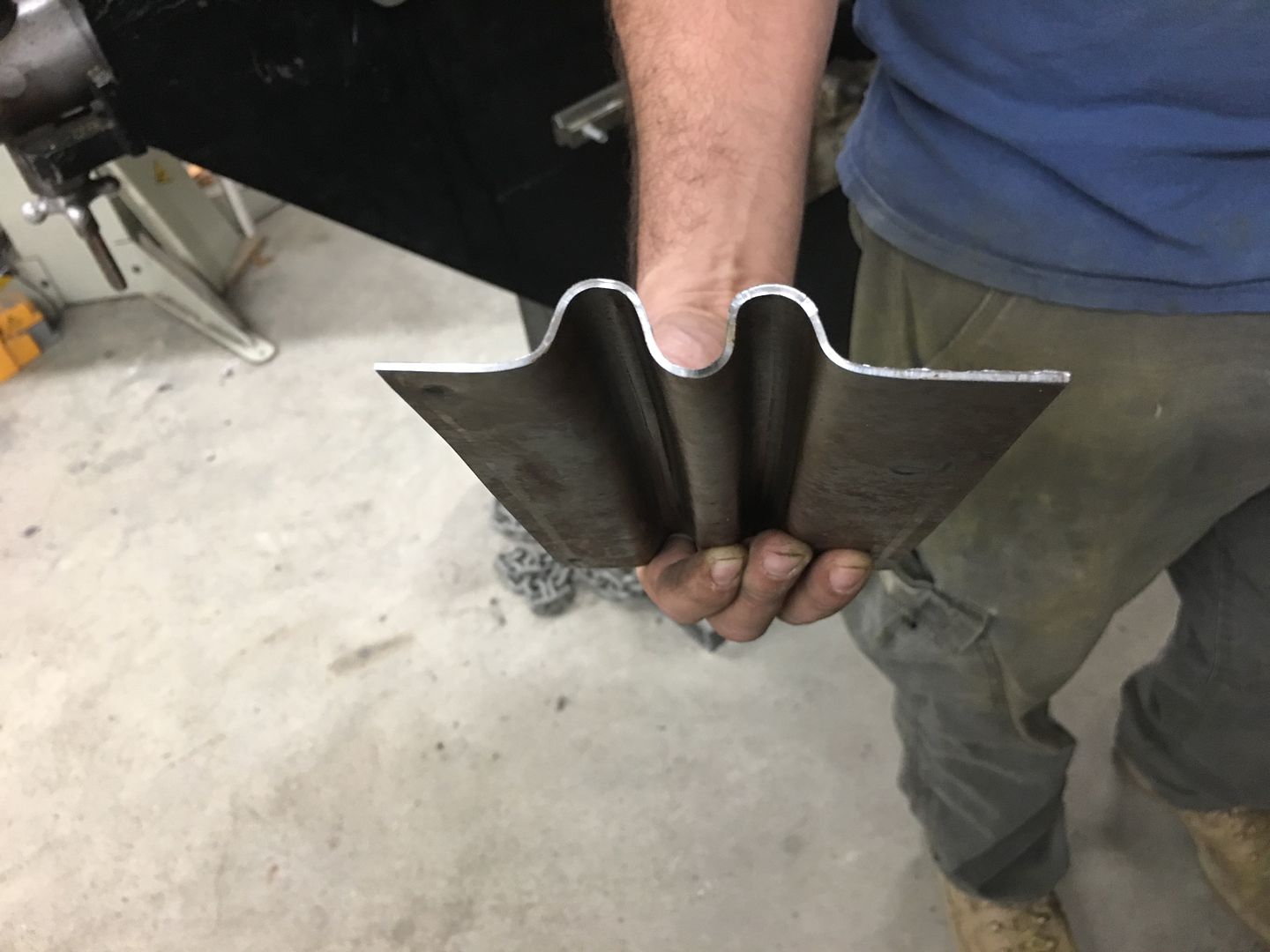
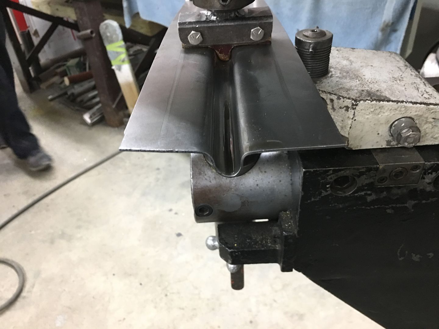
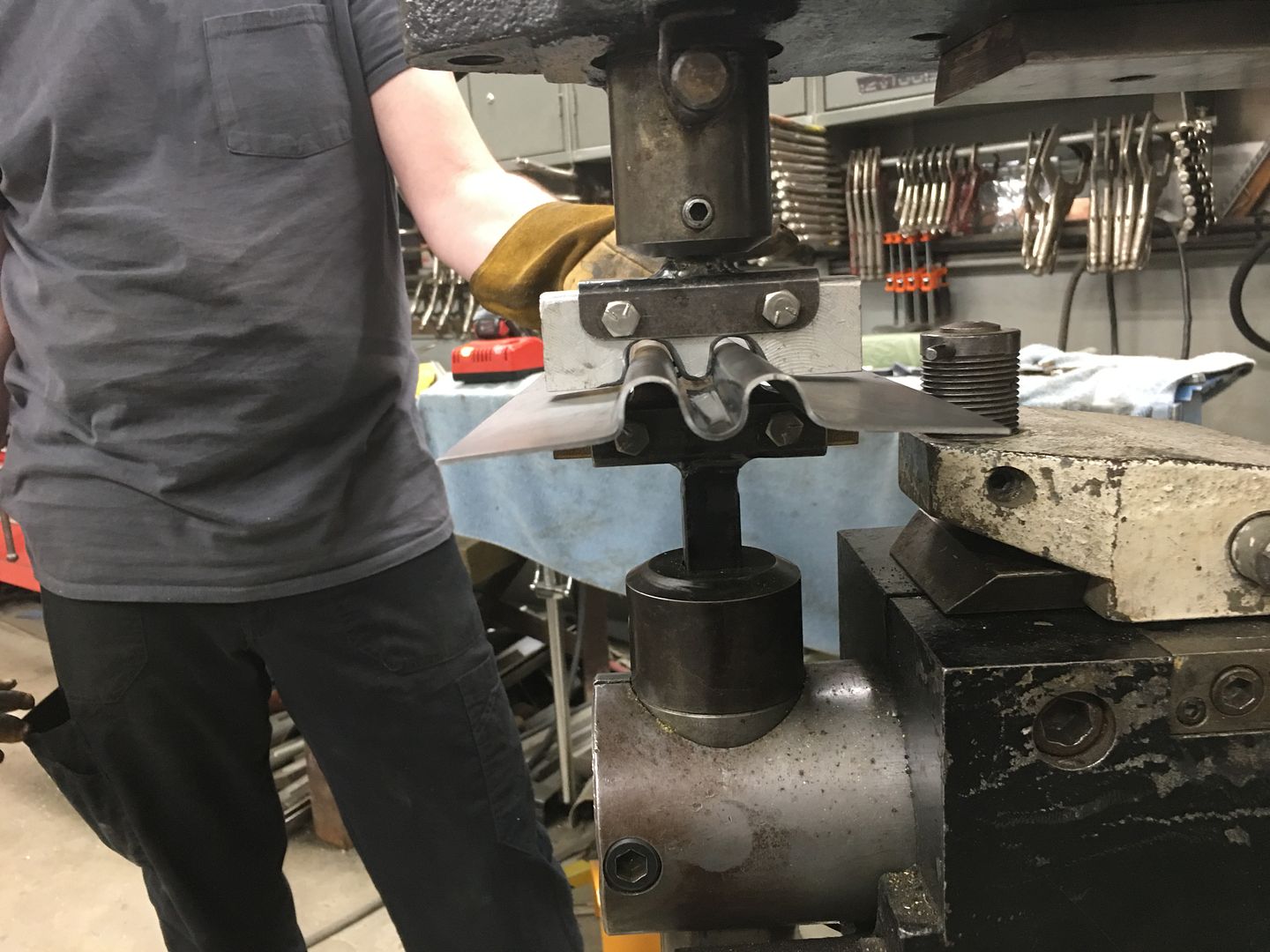
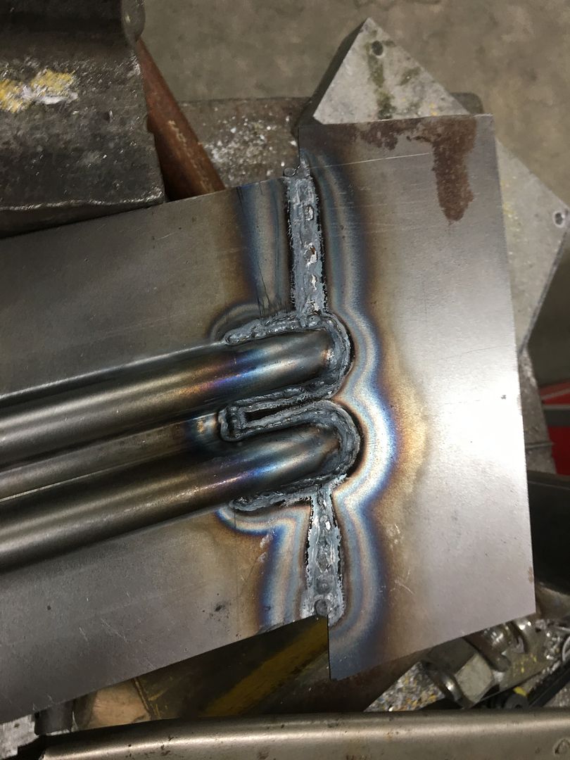
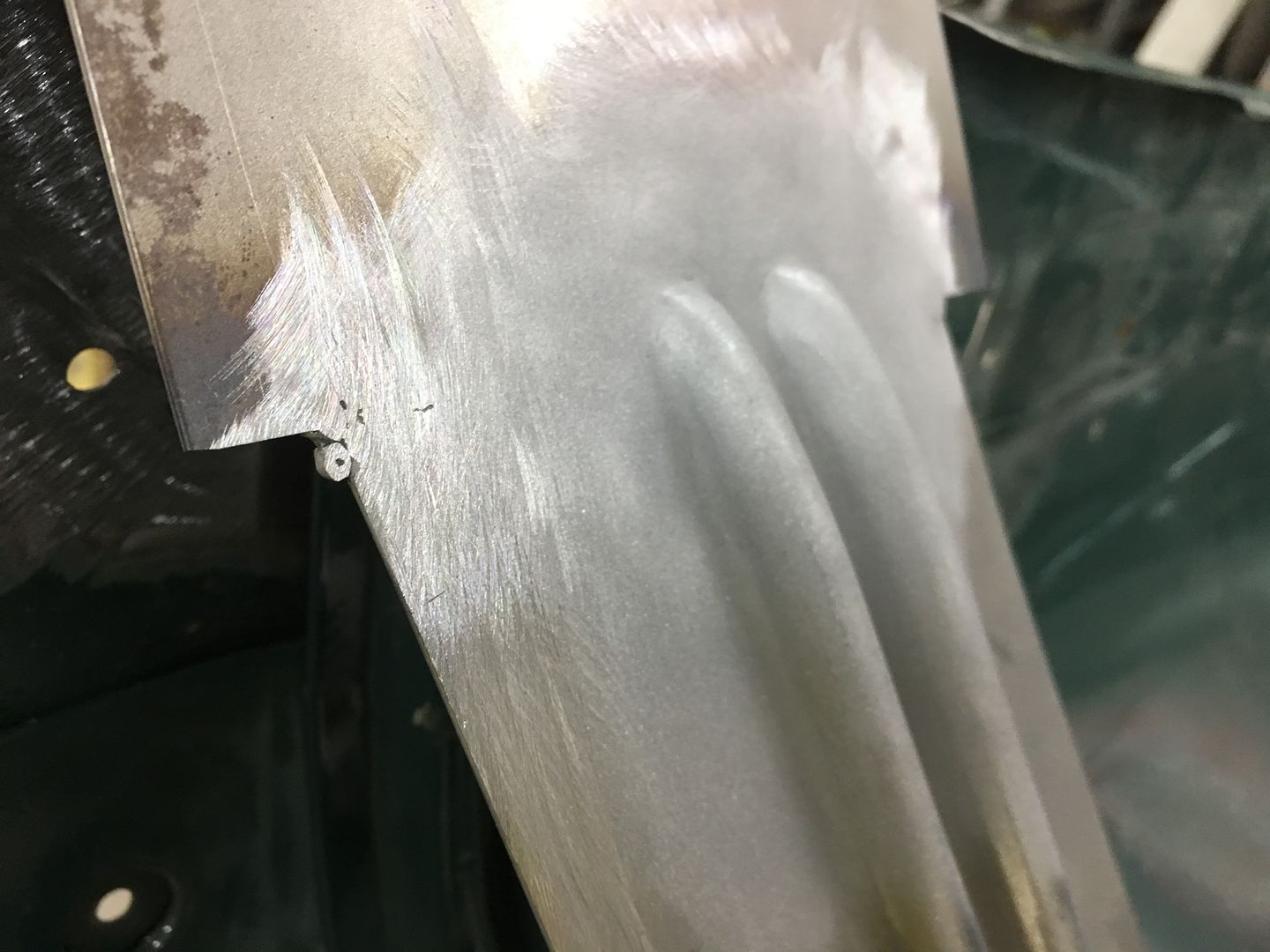
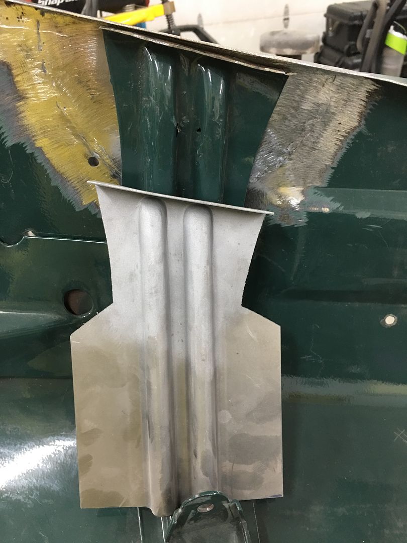
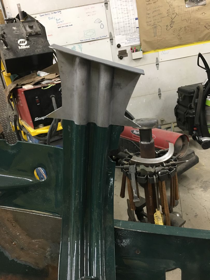
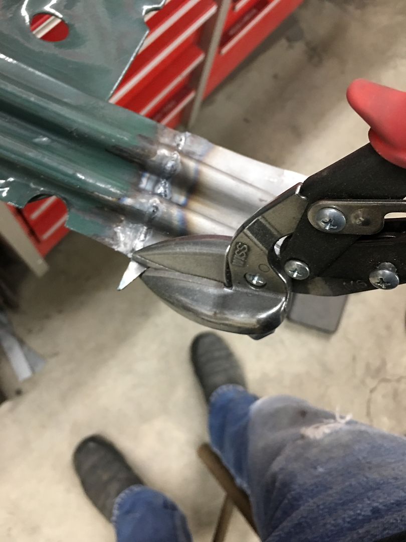
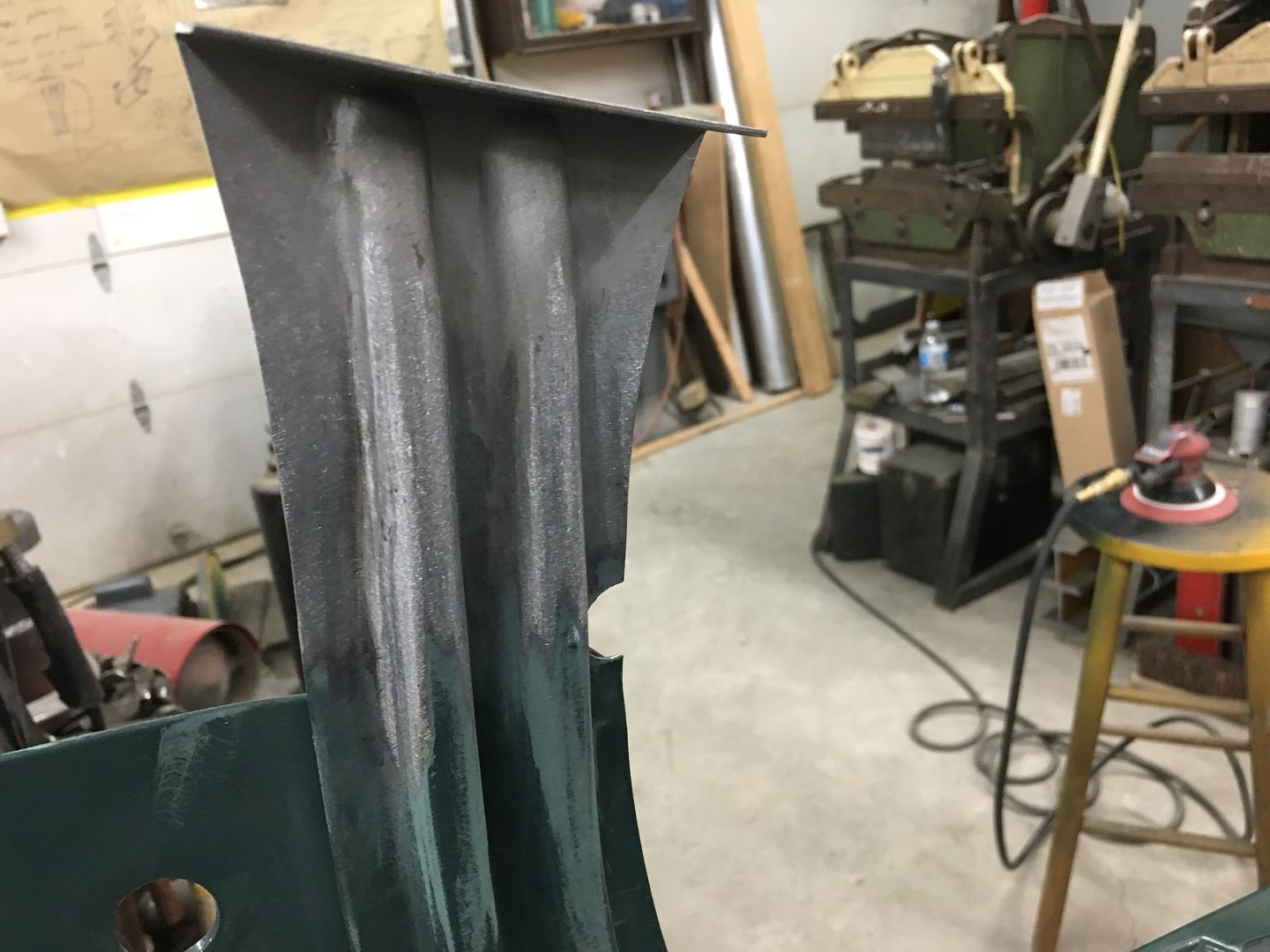
Then top die is changed out for the remainder of the ribs...


IMG_6643.JPG


IMG_6641.JPG


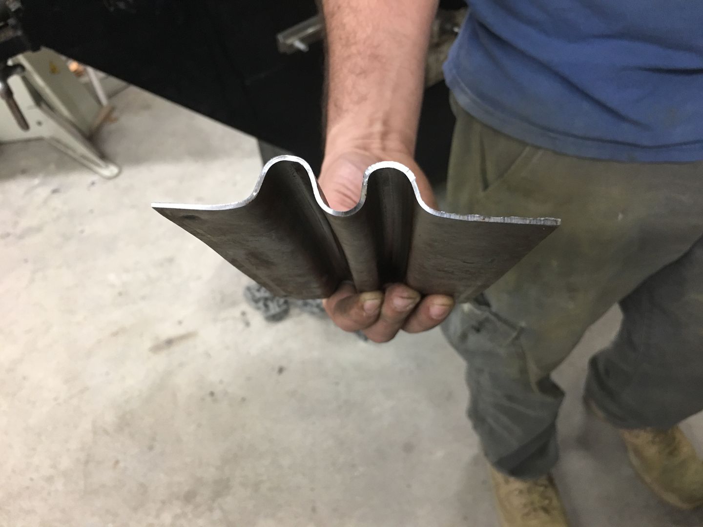
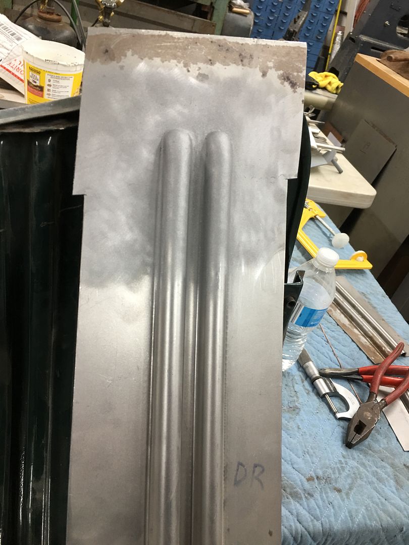
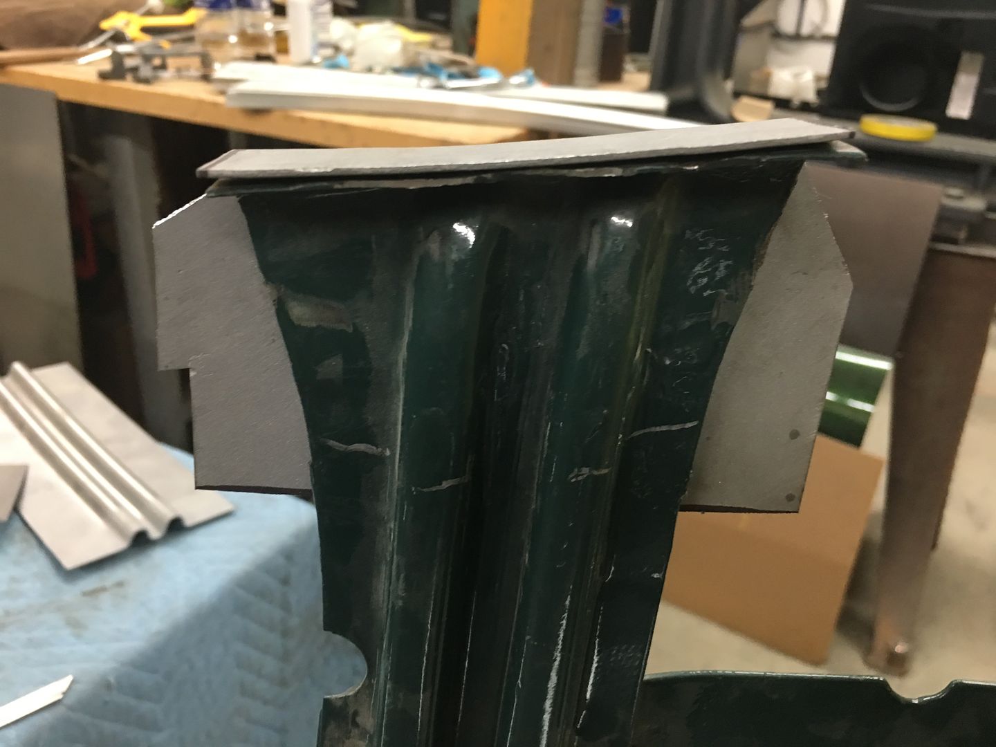
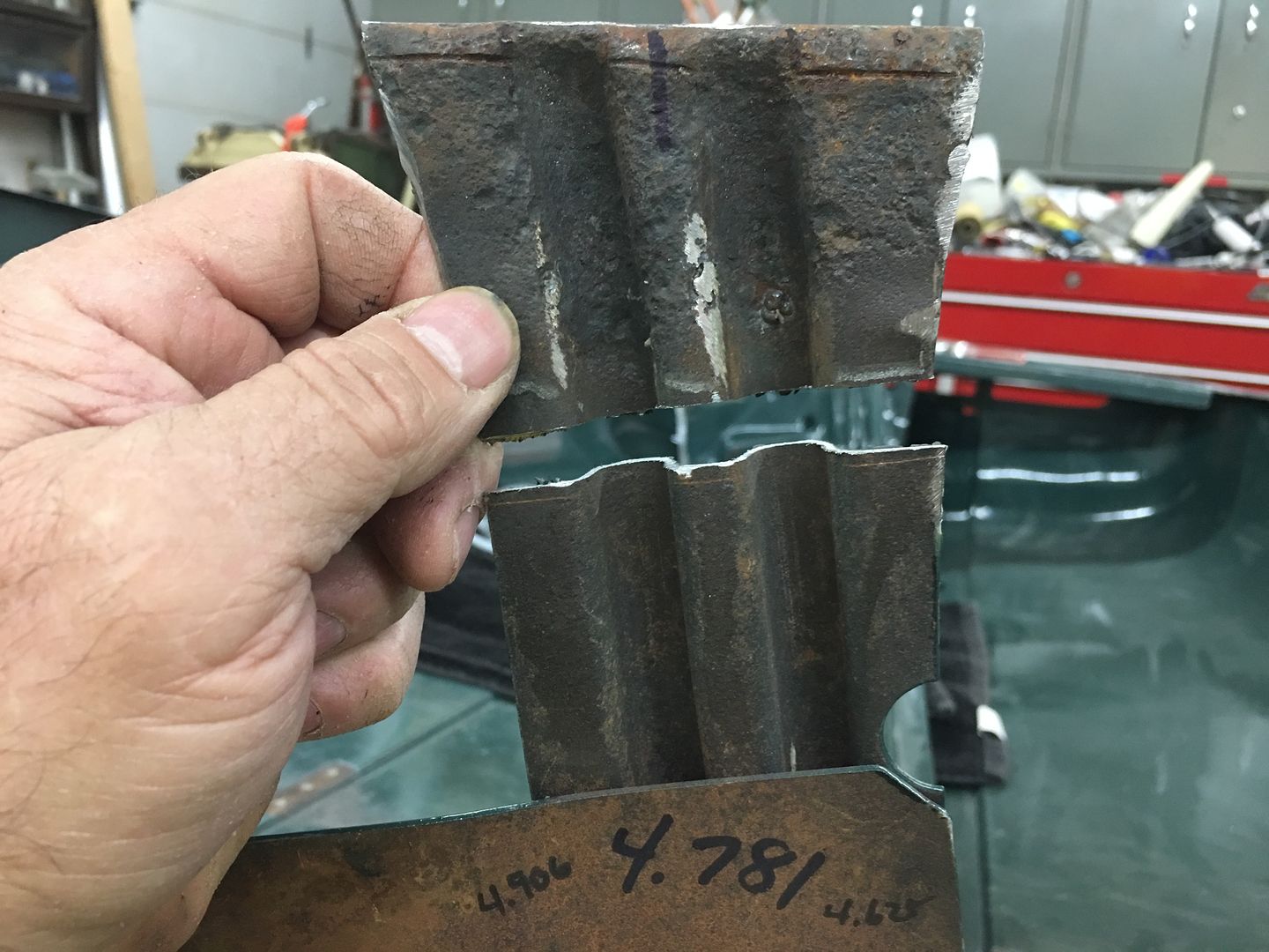
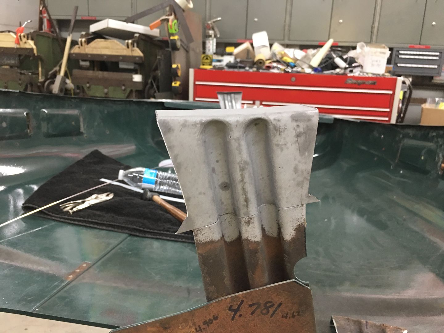
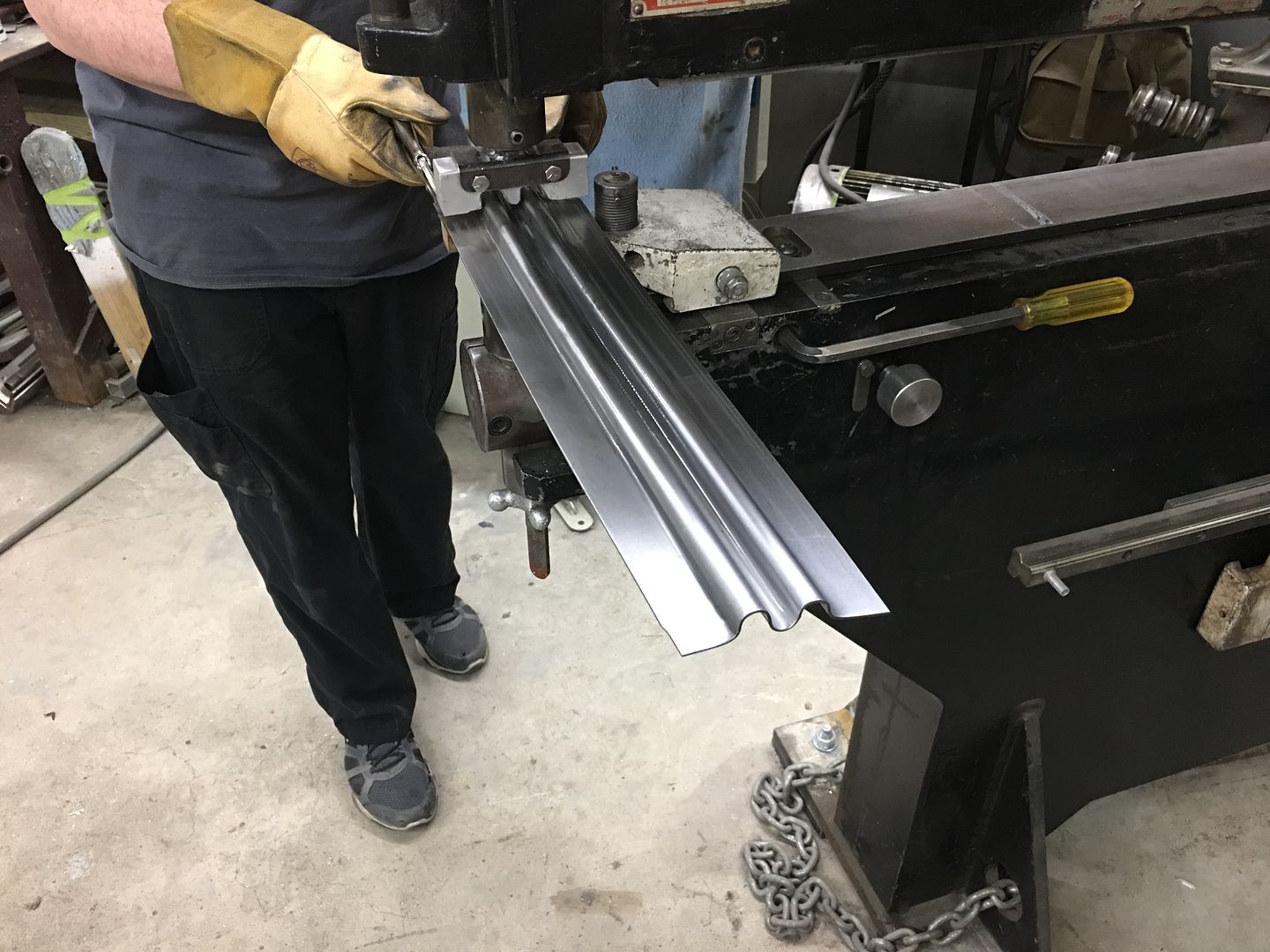
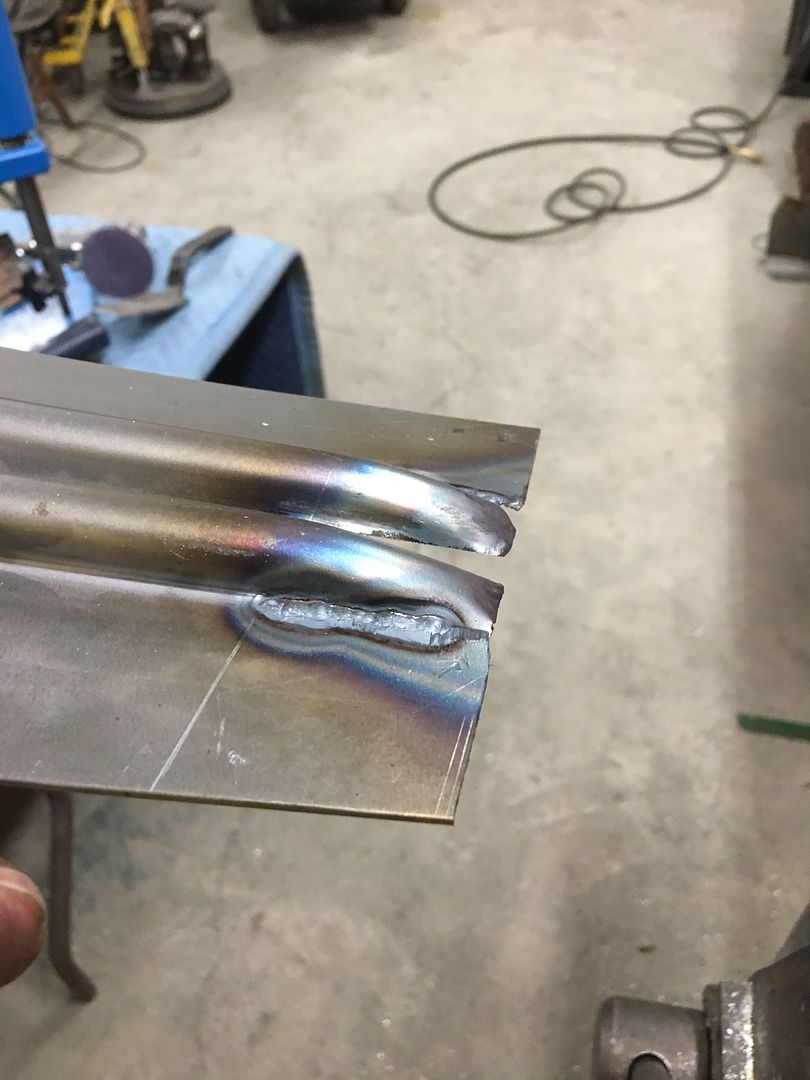
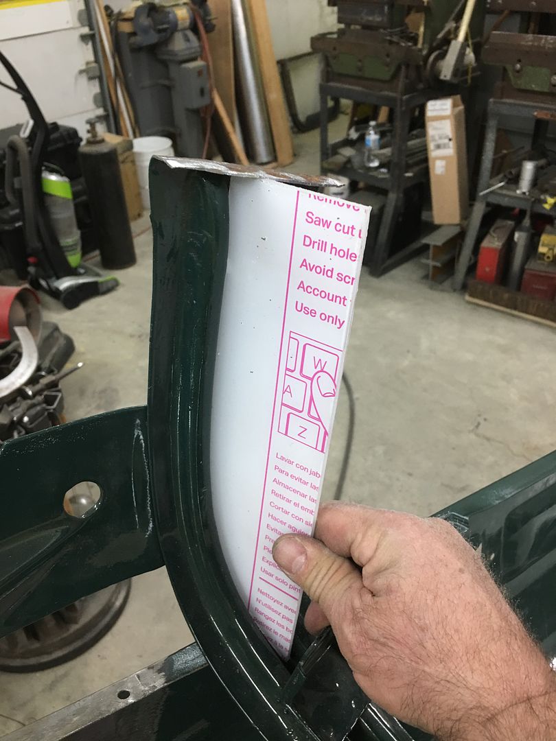
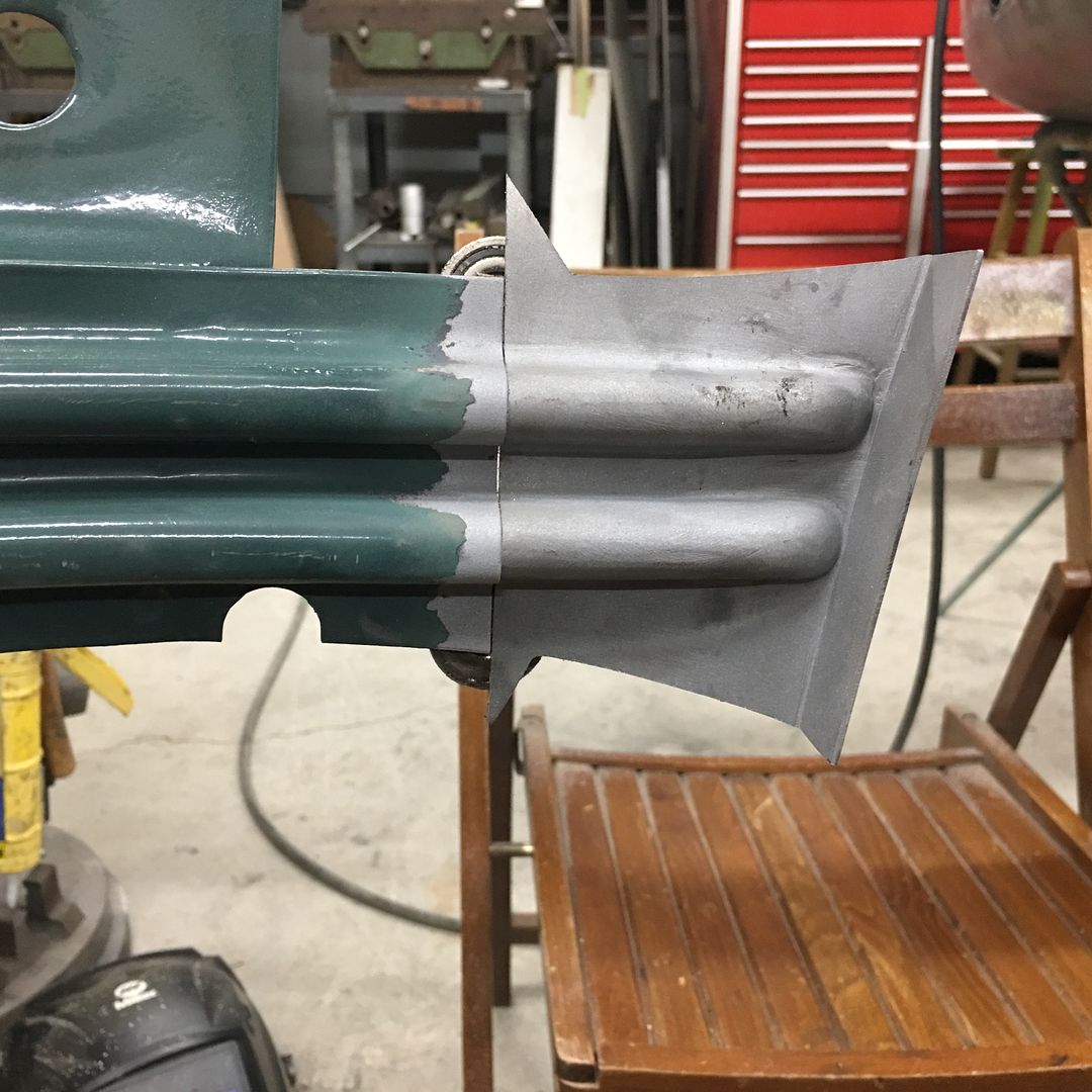
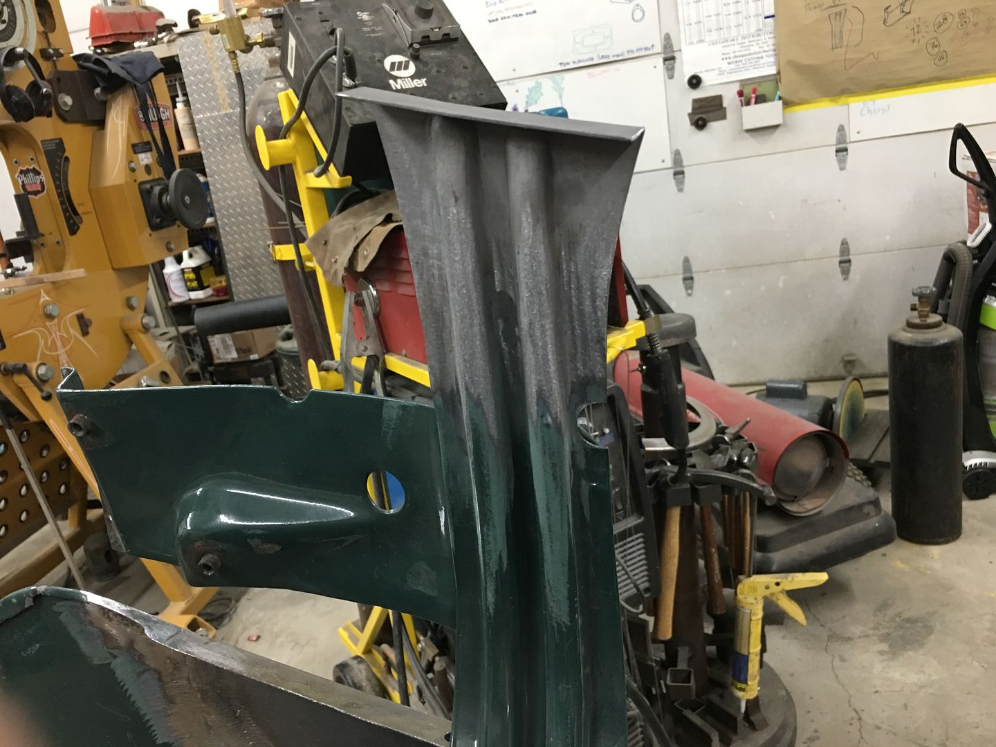
A bit of fine tuning needed, but looks like this process will work to repair the rot in the bottom of the brace ends..
 
To avoid these ads, REGISTER NOW!

BFBOB

Well-known member
Joined
Sep 20, 2011
Messages
5,073
Robert, first, a heartfelt Thank You for all the time and effort you've put into this thread. All the work I did on my '56 Chevy would have been much better if I'd had your guidance - alas, that was long before GJ even existed.

I have a question about the sheet metal clamps you sometimes use to hold a patch in place for welding. You - and others - stress that a perfect fit is important, but these clamps create a gap. Do you do anything to mitigate that, like cutting a notch in the patch as deep as the width of the clamp's through-piece?
 

MP&C

Well-known member
Joined
Oct 21, 2009
Messages
4,396
Location
Leonardtown, MD
Bob, for welding, normally I'll use vise grip c-clamps whenever the option exists.


IMG_3534.jpg


I can't remember the last time I used the "**** weld clamps" but at the time they were used for fitup only. When I started the welding process I would remove them as I went to allow the panels to fit tightly together. I have seen others notch for them but this allows more shrinkage when you go to weld the notches up, and will undoubtedly cause puckers that will need a bit more planishing to remove. Not insurmountable, just something to be aware of. So I'd recommend to just remove before you got to that area for welding.
 

MP&C

Well-known member
Joined
Oct 21, 2009
Messages
4,396
Location
Leonardtown, MD
Now to fine tune our dies for the hood brace. Looking at our original profile template, the first upsweep (red arrow) and second upsweep (yellow arrow) are both nearly vertical as compared to the opposite side.


IMG_6578a.jpg


Our first test run shows the first upsweep spread too wide, not enough vertical...


IMG_6642.JPG


Looking at the die that was made, a bit too much material was removed such that this vertical feature was lost...


IMG_6643.JPG


So a new die was made for the top, this time out of aluminum. The phenolic is somewhat easy to cut out but does have challenges in making crisp bend details, so lets see if the aluminum helps out..

Next run, this time we'll do two panels in case they work... First pass to draw the metal into the center rib...


IMG_6659.JPG


This is about 8 passes, each progressively deeper. The circle fixture to the right in the picture (white base) is used as a back stop to keep our rib centered.


IMG_6660.JPG


This is about 9/16 of depth, so quite a bit of draw.. Next, the new top die is added and goes through the same 8 progressive passes.. Note in the next picture the vertical upsweeps are both nearly vertical. Success!


IMG_6670.JPG


IMG_6662.JPG


IMG_6672.JPG


Matching up to the original, this looks like the right replacement.


IMG_6663.JPG


video version:


.
 

Dh3256

Well-known member
Joined
Mar 19, 2018
Messages
1,139
Very interesting! I have been wondering whether making wood dies and using a hydraulic press might work for making more complex shapes. Your success with thicker metal suggests this might work.

My goal is to make replacement panels for small areas that tend to rust. Specifically the 2000 era Chevy Malibu rusts out on bottom of the pillar behind the rear door. I've attached an example photo, it's the lower 3" or so that usually rusts.

I'm thinking I could make a wood die to rough oversize dimension, fill it with body filler and press against an unrusted example part, then make the mating die in a similar way. I could then use the die and a hydraulic press to form 20 gauge metal to make a replacement part.

Does that sound like it would work to make two or three pieces? Is the body filler likely to withstand the pressure?

For someone with minimal metal-shaping experience and skills, how would you suggest making these parts?

Thanks.
 

Attachments

  • malibu rear post.JPG
    malibu rear post.JPG
    23.5 KB · Views: 48

MP&C

Well-known member
Joined
Oct 21, 2009
Messages
4,396
Location
Leonardtown, MD
Body filler isn't likely to withstand the pressure of forming steel in a press, but there are some epoxies that will do the trick. If you can use the body filler to make a "mold" and then pour the epoxy into it... You will need a male and female die, and it helps to have alignment dowels or some other such method of keeping things aligned.
 
Last edited:

Slednut

Well-known member
Joined
Dec 20, 2012
Messages
2,550
Location
Washington state
I made this last year without any specialty tools, wish I would have taken more pictures. The gutter part of the drip rail had rusted through.
 

Attachments

  • Drip Rail 1.jpg
    Drip Rail 1.jpg
    64.1 KB · Views: 87
  • Drip Rail 2.jpg
    Drip Rail 2.jpg
    148 KB · Views: 88
  • Drip Rail 3.jpg
    Drip Rail 3.jpg
    45.8 KB · Views: 85

Dh3256

Well-known member
Joined
Mar 19, 2018
Messages
1,139
I made this last year without any specialty tools, wish I would have taken more pictures. The gutter part of the drip rail had rusted through.

How did you form the rail? I assume the slots were to allow it to bend for the curve and were then welded after bending?
 

MP&C

Well-known member
Joined
Oct 21, 2009
Messages
4,396
Location
Leonardtown, MD
I made this last year without any specialty tools, wish I would have taken more pictures. The gutter part of the drip rail had rusted through.


Far too many people shave drip rails for no other reason that they had rust in them. Good job in resisting the urge... :beer:
 

foogotz

Active member
Joined
Jun 8, 2016
Messages
34
Location
NY
Great thread. Have been reading through this for years ( multiple times). Thank you to Robert and everyone else. Very educational.
 

Slednut

Well-known member
Joined
Dec 20, 2012
Messages
2,550
Location
Washington state
Far too many people shave drip rails for no other reason that they had rust in them. Good job in resisting the urge... :beer:

Wow thanks, this coming from you means a lot, I remember you straightening me out on my welding with a couple simple sentences. I don't comment much but I always go to your thread first.

My friend has the same problem (picture) on his 67 Fairlane, once things get back to normal we'll tackle his drip rail problem.
 

Attachments

  • WVs Fairlane.jpg
    WVs Fairlane.jpg
    78.8 KB · Views: 72

Slednut

Well-known member
Joined
Dec 20, 2012
Messages
2,550
Location
Washington state
How did you form the rail? I assume the slots were to allow it to bend for the curve and were then welded after bending?

The only part of this piece that's visible is the bottom and outer edge once it's on the car. The slots were so I could bend it and most of them were trimmed off once I started attaching it to the car. The panel above the drip rail comes down and is spot welded to the top of this piece in the bottom of the gutter.
 

MP&C

Well-known member
Joined
Oct 21, 2009
Messages
4,396
Location
Leonardtown, MD
Progress on the hood, the bead details in the brace are offset on the ends to match the hood opening flange. So we use a Vernier protractor to find the angle, and transfer that to our panel. This is where the transition of the taper starts..


IMG_6674.JPG


Once tapered, the excess is removed from the bottom side and the outer seams TIG welded in place.


IMG_6685.JPG


A piece of round stock has a radius added to serve as a hammer form for the beads. They are hammered around and excess removed from the back side..


IMG_6688.JPG


A piece of 16 gauge cold rolled steel is trimmed to fit and TIG welded in place.


IMG_6691.JPG


IMG_6693.JPG


Welds dressed and media blasted..


IMG_6696.JPG


The bend line is transposed from the original. As this bend is slightly convex, it was started using a tipping wheel on the bead roller to a 45* angle, and then finished on the mag brake.


IMG_6706.JPG


IMG_6708.JPG


IMG_6709.JPG


A reminder of the carnage we are repairing:


A profile template is made prior to cutting out the old....


IMG_6713.JPG


IMG_6714.JPG


IMG_6717.JPG
 

MP&C

Well-known member
Joined
Oct 21, 2009
Messages
4,396
Location
Leonardtown, MD
Time to get the hood brace end welded in place. The overall measurement had been taken prior to cutting off the old one, down to the 14 gauge outer plate as a reference. So the new end is trimmed to match this dimension, then held in place with rare earth magnets. The center (inside) rib is aligned and tacked using the TIG....


IMG_6726.JPG


IMG_6727.JPG


Working outward, the panel surfaces are aligned and tacked as we go. Note the "batwings" left on the outside of the new brace end (yellow arrows). This will act as a heat sink when we make the outer tacks. Had these been trimmed to match prior to welding, the edge will have a tendency to burn back from the heat.


IMG_6729.JPG


The entire seam is TIG welded and then our batwings are trimmed using offset snips, then welds dressed..


IMG_6732.JPG


IMG_6734.JPG


IMG_6735.JPG


IMG_6736.JPG


IMG_6738.JPG


IMG_6739.JPG


One down......
 

NYBODYMAN

Well-known member
Joined
Sep 10, 2013
Messages
4,823
Location
NY
Nice work. What are you spraying in between the braces/hood for corrosion protection?
 

MP&C

Well-known member
Joined
Oct 21, 2009
Messages
4,396
Location
Leonardtown, MD
The entire brace will be media blasted and epoxy primed, the hood epoxy primed inside, and then plug welded back together..
 

NYBODYMAN

Well-known member
Joined
Sep 10, 2013
Messages
4,823
Location
NY
Nice! Will you use a cavity wax after plug welding back together?

I often wonder what products are used on these custom car shows on TV. These guys are fabricating entire floor pans, rockers, etc. That's a LOT of seam sealing and corrosion protection needed. I always wondered how they held up over years.
 

MP&C

Well-known member
Joined
Oct 21, 2009
Messages
4,396
Location
Leonardtown, MD
We’ll clean up the welded areas and flood with more epoxy. Then topcoat with the green again. The area under the brace was never painted from the factory, so either method has got to last longer than what they did. :thumbup:
 

Slednut

Well-known member
Joined
Dec 20, 2012
Messages
2,550
Location
Washington state
I really appreciate how you show the steps you took so us "want to be’s" have a chance to use your methods in our own shops.
 
To avoid these ads, REGISTER NOW!

MP&C

Well-known member
Joined
Oct 21, 2009
Messages
4,396
Location
Leonardtown, MD
I really appreciate how you show the steps you took so us "want to be’s" have a chance to use your methods in our own shops.


Isn't that the point of this thread? :beer:


I ran across a question on another forum that related to welder settings and much of the same info we've talked about in here before. It seemed a perfect "refresher" for this thread....


John said:
.......I have the same welder and have been welding my seams on the second setting with the feed set 35-40. I believe is is also the recommended setting listed on the welder. I can't imagine welding 18ga sheet metal on the #3 setting. Are you increasing your feed? What would be your feed for this?

Thanks,

John


MP&C said:
John, first, thanks for bringing this thread back up.

Now onto the show... Don't be afraid to use some scrap pieces and venture out of your "comfort zone" being what the chart on the machine tells you. I think too many people are of the mindset that you can only control the heat by using the heat control knob on the machine. Consider this once....Keep your heat turned up, control the heat the panel sees with trigger pull duration. Turning down the heat starts to move you toward compromising weld penetration.

For initial set up on a MIG, I look first and foremost for FULL WELD PENETRATION while using a tight fitting **** weld. Anyone can fill a gap, but is it truly fused together properly? If you have weld proud on both front and back side of a tight fitting joint, you have a weld that has taken place. We aren't using a caulking gun here. Next, in the case you do have too much heat as evidenced by a blowout, realize that first and foremost, the one thing you DO have is full weld penetration. The panel is "blowing out" because there is not enough filler wire going in for said amount of heat, hence the panel becomes the consumable wire. So before turning down the heat, add more wire feed speed until you no longer have blowout. Now you are where you can fine tune the settings but more importantly, fine tune the operator of the torch. Get out of your head that the heat control knob controls the heat that the panel sees. If you can increase the heat, increase the feed speed, and decrease the elapsed time of trigger pull, you will in essence have a full penetrating weld with less proud for less planishing needed, less grinding needed. More heat gives you a flatter weld.

The colder your weld, the more proud you have on the top side of the panel, the less penetration you have in the panel. Once you have a cold joint, grind it off. You can pile on another 1/2" of blob, it will never penetrate properly.

And because I have plenty of pictures, here's some test samples that I did. Side note..... you ran out of wire and just installed a new roll. Whether it's the same brand you used before or not, do some test samples if you are welding sheet metal. Always find out how everything works on a practice piece before jumping in on your good panels. Much of todays welding wire is made who knows where of who knows what. Get comfortable with it on scraps.. Also, note the pictures below show my test coupons in free air, just as your quarter panel on a car is. We don't do test coupons laying on a steel workbench because it is a heat sink and does not match the same conditions as the panels on your vehicle. Your practice should match those same conditions as your vehicle, so you are setting up the welder, fine tuning the settings, and fine tuning the operator...…all in the same conditions that exist on the vehicle... before you jump on your good panels


Installed .035 ER70S-7 in the machine, dialed in the settings for 3/16 thick steel, and ran some test welds... YES! HEAT SET FOR 3/16 STEEL!

Note the minimal HAZ for the size of the weld dot, note the minimal build in the side profile shots...………..

Picture648.jpg


Front side....

Picture645.jpg


Picture646.jpg


Picture618.jpg


Rear side....

Picture647.jpg


The duration of trigger pull on these was less than a second, likely about 1/2 second. So the end goal of your practice should be welder setup, adjusting operator technique, and minimal proud/flatter welds having full penetration..
 
Last edited:

MP&C

Well-known member
Joined
Oct 21, 2009
Messages
4,396
Location
Leonardtown, MD
Starting on the other end of the hood brace, this one not as rotted as the other but has issues just the same. One of those "while we're here" things....

The ribs are trimmed and ends rounded.. A piece of flat 16 gauge is trimmed to fit..


IMG_6743.JPG


IMG_6744.JPG


IMG_6745.JPG


IMG_6746.JPG


tacked together....


IMG_6747.JPG


….then the photographer went on strike until we got to this...


IMG_6748.JPG


IMG_6749.JPG


IMG_6750.JPG


We'll get this trimmed and installed tomorrow..
 

MP&C

Well-known member
Joined
Oct 21, 2009
Messages
4,396
Location
Leonardtown, MD
More progress on the hood, here is the other end of the hood brace.


IMG_6813.JPG


Looking at the back side, you can see where a few holes were welded closed the last time it was painted, and the severe pitting and new holes that we have. A testament to the fact that what shows is always the tip of the iceberg. Although better than the passenger side, this is definitely one of those "while we are here" things. Do it right, do it once. (grinder marks were mine)


IMG_6816.JPG


IMG_6815.JPG


With our new replacement all one piece, the next step is to bend the flange that spot welds to the hood skin. A tipping wheel in the Fasti-werks bead roller makes quick work of it. The bend line was transposed from the original and an initial pass under the tipping die marks the crease line a bit better, Then successive passes are made, lifting slightly with each pass. This is done until the beads interfere with the tipping die.


IMG_6809.JPG


IMG_6810.JPG


Then the partial bent flange is clamped in the magnetic brake for the remainder of the fold. This brake allows us to use a die on either side of the bead details, where a full die may inadvertently push in on the beads.


IMG_6817.JPG


IMG_6819.JPG


End gets cut to length and marked for initial trimming


IMG_6823.JPG


IMG_6824.JPG


Looks like we may have enough bead stock left for another couple of ends.


IMG_6821.JPG


That's where we left off yesterday, we'll see about welding the new end on today..


.
 

stinkity stoink

Well-known member
Joined
Apr 8, 2007
Messages
729
Location
New Jersey
Nice job Robert !
You’re sheet metal mig welding reminder came at a perfect time. I forgot about that technique and had to do some patching in a wheel well that was tough to tig. You’re method was perfect, nice flat beads with good penetration..
Thanks
 

MP&C

Well-known member
Joined
Oct 21, 2009
Messages
4,396
Location
Leonardtown, MD
Dave, that's all TIG welding you're doing..


Our last end for the hood brace. Off with the old.....


IMG_6834.JPG


Then it gets trimmed to our scribe line and the end media blasted in prep for welding. Our new end is test fit and trimmed until we get the right distance to our reference marks. The "batwings" give us a heat sink at the edge for less chance of burning back the edge at the weld.


IMG_6837.JPG


The center rib is aligned both on the sides and the face, and tacked in position using the TIG.


IMG_6838.JPG


The pieces are aligned as we work outward, tacking as we go. A "corking tool" is used as a dolly where any bumping may be needed for alignment.


IMG_6842.JPG


IMG_6840.JPG


Tacked...


IMG_6846.JPG


Welded....


IMG_6847.JPG


Welds cleaned up and end angles compared..


IMG_6851.JPG


IMG_6854.JPG


IMG_6855.JPG


Now we can get back to straightening sheet metal..
 

WoodsTruck

Well-known member
Joined
Jan 12, 2013
Messages
1,019
Robert,

Can you add any comments on the use of an epoxy primer behind weld patches?

I am helping a neighbor work on a hood that I think I need to pour some primer/sealer type product in and slosh around to coat exposed goblins behind the patch panel that I have no other access to. Any suggestions?

Thanks
 

MP&C

Well-known member
Joined
Oct 21, 2009
Messages
4,396
Location
Leonardtown, MD
If you look at some of the work in my shop thread, we have made 1-1/2" wide by 4-1/2 foot long paint rollers to get the entire rocker panel coated on the inside. We have poured paint and used make shift extensions on brushes to help get good coverage. We've put new door skins on, epoxied skin and door frame separate, scuffed, put together, and poured in more epoxy while rotating door around to seal up that seam once and for all. So in a nutshell, whatever works. Keep in mind that the epoxy, once cured, is fairly tolerant of heat from welding. So if you want to pre-coat those difficult areas and stay about 1/4" back from the seam, it limits what you have to do at the end..
 

MP&C

Well-known member
Joined
Oct 21, 2009
Messages
4,396
Location
Leonardtown, MD
We have a few more spots to fix from cracking and fatigue, namely the holes on the underside for the rubber hood bumpers. We've already repaired three, and from the looks of it, need to take care of the remaining three..


IMG_6895.JPG


IMG_6896.JPG


IMG_6897.JPG


18 Gauge x 1/4" plugs were TIG welded in to fill the existing holes, and a copper backer gives us a bit of a heat sink so the cracks/fatigued areas don't blow a big hole on us..


IMG_6904.JPG


IMG_6908.JPG


IMG_6909.JPG


Welds were dressed on both sides of the sheet metal, and new holes drilled slightly in farther from the edge to help slow down the reappearance of cracks.


IMG_6943.JPG


IMG_6944.JPG


IMG_6945.JPG


Next, I'm sure everyone has seen how these hoods can oil can, show low spots, and try to flop around while driving down the road. Part of that is abuse over the years, fatigue, etc. Any low spots invariably result in a loss of support of the hood and will show oil cans or loose areas.


IMG_6966.JPG


A good tool to check the crown of the hood is a long straight edge in the form of a 36" rule. If you don't have one, most hardware stores sell aluminum flat bar for a few dollars that will make a good profile template. For this style hood, lows are bad, straight is better, and a slight crown in the center crease along the entire length of the "flat" area of the hood is optimal.. This gives the support to help eliminate those oil cans and floppy hoods.


When we started there was an obvious area about 12" forward of the rear edge, dead center, that appears low, and was easily pushed downward. In order to better define the center crease and provide the support needed, we will use a sand bag (a rather large one) and lightly hammer from the bottom side into said bag with a purpose built "punch".


IMG_6967.JPG


IMG_6969.JPG


IMG_6968.JPG


In order to keep the back portion of the hood down against the bag for support, we used our latest "metalshaping" tool to hold the front of the hood up, an engine hoist..


IMG_6958.JPG


A reference mark is used on the inside, measured and centered...


IMG_6961.JPG


The crease was checked for low spots prior, and the bottom marked. The "punch" is dragged along the centerline and tapped as you go. Flip the hood over, check crown, remark as needed, repeat. We got to a good straight/slight crown and the oil can disappeared. Pushing along the entire center crease was a nice tight support now..


IMG_6962.JPG


IMG_6964.JPG


So if you are having issue with your hood, I would suggest first checking your center crease.
 

stinkity stoink

Well-known member
Joined
Apr 8, 2007
Messages
729
Location
New Jersey
Thanks for that explanation Robert. I have a 2 piece hood right now that I believe shrunk from welding the seam.
Where is that beater bag from? I’m guessing it doesn’t get moved around
Thanks
Dave
 

MP&C

Well-known member
Joined
Oct 21, 2009
Messages
4,396
Location
Leonardtown, MD
Dave, got a cowhide and had upholsterer sew it up. No, it hasn't moved since we dumped 5 ea 5 gallon buckets of used media from the blast cabinet in it. The center cover is held on with 2" wide Velcro that was sewed on.. :beer:
 
Last edited:

flynfrog

Member
Joined
Nov 26, 2017
Messages
6
Long time listener first time caller. I used to do some hack paint and body back in the day. Took Gene Windfields class probably 10 years ago. I have probably read this and your other threads 10 times now. I am tackling the dreaded death foam on the wifes super beetle. Decided to see if I could shape a panel and how close I can get. Just stretched with a BFH on a 2x4 then upset the flange with some flange pliers. Moved on to some hammer and dolly with a chunk of rail and some HF hammers. It seems to be coming along pretty well. Trying to tighten up the radius in the bottom of the flange any suggestions. Trying to decide if I want to invest in some more tools right now.
pwA9hjL.jpg

GLUY4BE.jpg

Ou4OetZ.jpg

70zl5nA.jpg

Qzvm3MX.jpg

yJFabbo.jpg


Second question I am at the same time doing a few spots of rust repair on my E34 wagon and shaving the roof rails. Is there a punch that make near .400 plugs. Or could I buy you a beer and some shipping to punch me some.

zFmnHni.jpg
 
Last edited:

MP&C

Well-known member
Joined
Oct 21, 2009
Messages
4,396
Location
Leonardtown, MD
Responses in Blue


Long time listener first time caller. I used to do some hack paint and body back in the day. Took Gene Windfields class probably 10 years ago. I have probably read this and your other threads 10 times now. I am tackling the dreaded death foam on the wifes super beetle. Decided to see if I could shape a panel and how close I can get. Just stretched with a BFH on a 2x4 then upset the flange with some flange pliers. Moved on to some hammer and dolly with a chunk of rail and some HF hammers. It seems to be coming along pretty well. Trying to tighten up the radius in the bottom of the flange any suggestions. Trying to decide if I want to invest in some more tools right now.

Is the foam something added by the last owner or is that factory? Looks like a nice water trap/rust generator. I'd get rid of all of it while you're there. If you need less radius on your patch where the bend is, try laying it across a piece of flat bar or angle iron on one of the sharp corner edges and gently tap down one side of the crease, then the other. That should get things closer to a sharp 90*.. Light taps so you don't add dents/dings, and repeat until you get the radius you're looking for.

Second question I am at the same time doing a few spots of rust repair on my E34 wagon and shaving the roof rails. Is there a punch that make near .400 plugs. Or could I buy you a beer and some shipping to punch me some.

zFmnHni.jpg


Is the shaving of the drip rails to remove rust? In most cases you are going to have a field day to keep the resulting seam straight. I'm not a fan of shaving drip rails primarily because people do it as a perceived short cut to fixing rust. For your hole plugs, try to find a local machine shop with a turret punch that can make your plugs for you, I would say to use 18 ga cold rolled. I don't have one personally, but perhaps someone else reading this that has one will chime in..
 

flynfrog

Member
Joined
Nov 26, 2017
Messages
6
Yeah the foam was factory. Its known as the death foam for VW beetles they started to add it in the late 60s. We have removed it all and are sanding/blasting the surface rust on the inside. I was planning an ospho treatment but got scared with the adhesion issues with epoxies.


For the wagon its not the drip rails it's the roof rails for mounting bike racks and such

I think we might have some turret punches at work Ill check next time I go in. Thanks for the advice.
 

mopar4don

Well-known member
Joined
Mar 9, 2013
Messages
103
Hey Robert,
Nice job on fixing the low spot (oil canning) of the hood.
It is amazing what you can do with metal!

So now your using a TIG?
Are you finding it works better than the MIG?
 
To avoid these ads, REGISTER NOW!
Top Bottom