To avoid these ads, REGISTER NOW!

Wiring SPST switch for Harbor Freight bandsaw. Crappy instructions...

67carl

Well-known member
Joined
Dec 10, 2013
Messages
3,911
Location
California
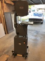
I'm assembling my 14" HF bandsaw and am a bit frustrated by the instructions. Parts aren't differentiated very well (or at all), some things that are supposed to be already assembled are not, while things I'm supposed to put together already are. There were a few loose bolts/washers/nuts floating around in thd box and I haven't figured out where they go yet. Steps are missing and/or so vague it's maddening.

But the main issue I'm having is wiring. The wire from the power cord is supposed to be connected to the switch terminals already, but it wasn't. The instructions say just plug in motor wires in the same positions as the power connections and give no other instruction. There's a simple pic but no terminal numbers or helpful info. I connected the motor and cord wires based on the orientation of the terminal in the drawing, but won't plug it in until confirmed.

On the back of the terminal each spade has a number - 1, 3, 4, 6. This is a simple single throw on/off switch, so SPST. But I can't find a diagram of a SPST with these four terminals. I connected motor black to 4, white to 1, power cord black to 6 and white to 3.

Thoughts?

Also, the box is **** and the wiring insulation was stripped to far back and is exposed outside the box. I'm going to replace it with something sturdy and make better connections.
 

Attachments

  • 5E0E8364-24FA-4749-85A4-5269551F4282.jpeg
    5E0E8364-24FA-4749-85A4-5269551F4282.jpeg
    246.9 KB · Views: 58
  • C9129FCF-89E9-4583-A78F-86230828F747.jpeg
    C9129FCF-89E9-4583-A78F-86230828F747.jpeg
    301.9 KB · Views: 55
  • BE74FC86-8837-4FC9-B243-A66F58CC72F8.jpeg
    BE74FC86-8837-4FC9-B243-A66F58CC72F8.jpeg
    347.4 KB · Views: 49
  • 0F31718D-3559-455D-9F86-06183055D99B.jpeg
    0F31718D-3559-455D-9F86-06183055D99B.jpeg
    301.1 KB · Views: 50
To avoid these ads, REGISTER NOW!

The Cobbler

Super Moderator
Staff member
Joined
Oct 24, 2013
Messages
25,962
Location
Niagara Region, Ontario, Canada
that is correct wire orientation, for every tool switch that looks like that one that I have seen/
you could always check continuity with a meter of you have one
that schematic in the manual makes nos sense
 

The Cobbler

Super Moderator
Staff member
Joined
Oct 24, 2013
Messages
25,962
Location
Niagara Region, Ontario, Canada
that is correct wire orientation, for every tool switch that looks like that one that I have seen/
you could always check continuity with a meter of you have one
that schematic in the manual makes nos sense
(EDIT) it sort of makes sense, but they've labeled the white from the motor where the ground actually is
 

RTM

Well-known member
Joined
May 13, 2019
Messages
13,231
Location
SF Bay Area
Actually double pole, single throw, DPST. The center contacts should be the inlet line from the wall, the outer ones shoulf go to the motor. Each side, in your 1st photo, should be the same color, as you have done. Live dangerously, plug it in, hit the go switch.

if there were contacts at the bottom, it would be DPDT.
 
OP
6

67carl

Well-known member
Joined
Dec 10, 2013
Messages
3,911
Location
California
(EDIT) it sort of makes sense, but they've labeled the white from the motor where the ground actually is

Yes! I saw that and it was one of several WTF!? moments I experienced going through the instructions. The mobile base I bought at the same time and installed before adding the motor and cast iron saw assembly was even worse (you can see it under the saw in the last pic). Great product - heavy, thick gauge steel but shite for instructions. Thankfully lots of Youtube videos for that.
 
OP
6

67carl

Well-known member
Joined
Dec 10, 2013
Messages
3,911
Location
California
Thanks all for the help. I'll plug it in tomorrow and see if I trip the breaker.
 
To avoid these ads, REGISTER NOW!
OP
6

67carl

Well-known member
Joined
Dec 10, 2013
Messages
3,911
Location
California
is that a 67 firebird in your avatar and in your driveway ?

It's the Firebirds cousin - 67 Camaro RS

also is that a wood saw? I would drill a hole in the bottom of the plastic switch shroud to let the sawdust fall out, othersie it will probably fill up with dust .

Yes, it's for wood. I think I'm going to replace the switch and the box. The box has several holes in it (to pass the wires through) and no mechanism to seal them, or even to clamp the wires, so they just free float. I can't imagine they got away with this as a design, and would guess those parts didn't make it in the box? This is one of the things that frustrate me about the instructions. The page I posted above is everything they have in there about the electrical installation. 1 page of vague instruction and a simple diagram.
 

Attachments

  • RC.jpg
    RC.jpg
    173 KB · Views: 37

dogdog

Well-known member
Joined
Nov 15, 2011
Messages
12,711
??? Figure 14 is pretty self explanatory. It's a DPST, incoming power on the middle pins, and motor on the outer pins, not that it matters functional wise, but it is just the standard conventions for all equipment bandsaw , drill press, compressor, tablesaw etc etc... . That is almost a pictorial there.. not sure whats the confusion.
 

FMB4

Well-known member
Joined
Jan 19, 2017
Messages
2,926
Do think that you may have been sold an 'open box' (i.e. returned) band saw?
 
OP
6

67carl

Well-known member
Joined
Dec 10, 2013
Messages
3,911
Location
California
Do think that you may have been sold an 'open box' (i.e. returned) band saw?

Not sure, but parts that would need to be bagged were in sealed bags. I didn't see any signs of wear or scratches from assembly.

Apart from the (what I consider) poor instructions and a few loose bolts/screws/washers, it seems in good order. All the parts fit together and holes line up. There is a touch of rust on some cast iron pieces that I'm not sure if I should address (i.e., wire brush/sand then prime/paint) or not. I hope to have time to finish it today and get it running.
 
OP
6

67carl

Well-known member
Joined
Dec 10, 2013
Messages
3,911
Location
California
While I'm enduring a long zoom meeting for work I decided to take a break from the WGT Golf game I'm playing :) and download the bandsaw assembly instructions to see what's next. Low and behold, they are updated and much better. Clearer directions and they also have some assembly steps in a different order than the paper version that came with the saw. Take a look at the motor wiring page below. I said in my original post there was no mention of securing the wires, but they addressed that in the version on their website. They also corrected the text identifying the ground wire as white...6C11162D-49C0-4A07-8097-A9F3500D60A5.jpeg
 
  • Like
Reactions: RTM
To avoid these ads, REGISTER NOW!
Top Bottom