To avoid these ads, REGISTER NOW!

ZMotorsports Shop Projects 2.0

mbryson

Well-known member
Joined
Jan 4, 2014
Messages
133
Location
Bountiful, UT
I have a "Thumbler's Tumbler" used for reloading and silver-smithing. One has two bowls, one with brass cleaning/polishing media, and another with stainless steel pins and needles for the silver-smithing.
Honestly, the bowl is the hard part, best to just buy it. The vibration is simple. Put a plate on three springs to support it. Run a piece of 1/4-20 all-thread up in the middle to hold the bowl and it's lid on. Bolt a cheap electric motor to the underside of the plate with the shaft pointing down. Take a piece of 1/2" plate about an inch long and bore a shaft sized hole in it near one end. Drill in sideways for a set-screw. Clamp that onto the motor's shaft. That is how every bowl type thumbler that I've seen is made.

I was gifted with another tumbler and I've been looking into media for cleaning hardware and finishing small brackets with it. The tumbler is only a small part of the equation. The media used is a huge consideration, and the range of media large and wide. I've yet to find anything to give me much direction past "I've used this media and it did this for me" kinds of blogs and posts, which don't really help since they weren't doing what I want to do. Seems like there's a lot of trial and error out there, with error being common and incurring some cost.

The more industrial types of tumbling/deburring machines out there are no more complex, but they have a lot of lessons learned type nuances built into them. When I worked for the racing engines shop they had a hardware cleaning machine that I think that I've described here in the past. Two square boxes made of perforated metal with a latching lid. They were partly filled with bias cut hardened steel shot. The boxes had a ring of ~1/2" round bar welded to all 4 top and bottom corners. Load up a box and then turn it sideways and set it down inside the machine on two shafts. The shafts were partly submerged in solvent. A timer controlled how long the motor would spin those shafts. The whole thing was incredibly noisy, but the hardware came out clean and slightly burnished. I took to using it for the final finish on all of the small brackets that I made while working there.

Inspired by that I tried a doing the same thing with the stainless media filled bowl. It didn't work too well. Maybe bolts will work, but even small brackets are out of the question.
 
To avoid these ads, REGISTER NOW!

ntsqd

Well-known member
Joined
Jan 22, 2005
Messages
997
Location
Lower left coast
Those are all about the same, yes. May even ultimately all be built by the same company, wouldn't surprise me.

[EDIT] These are likely to be slow unless you use the right media in them. Something like the crushed walnut shells that I use for cleaning & polishing brass cases will eventually make something those Dana 30 Inspection Cover bolts look really nice, but it might take a full day to do it. With a better media it could cut that down only 30 minutes.
 
Last edited:

4 FN 27

ALLIANCE MEMBER
Joined
Oct 19, 2015
Messages
4,635
Location
Minnesnowta
Thank you for the refresher course Mike. Been about 20 years since I set up a Ring and Pinion. Now the time is here again...just waiting on a few Tools to arrive to replace the ones gone missing from borrowing them out over the years.

It is be like Mike week at my Shop.

IMG_6942.JPG

After welding new ends on to replace those that were welded incorrectly by the prior owner and dropping the Carrier in with the Original Shims there is a slight bind for about 45-60° of a full revolution. That along with the the Ring Gear mounting holes being over torqued causing the Bolts to bind just dropping them in I am thinking a new Carrier might be the right answer. Sleep insurance.
 
OP
Z

zmotorsports

ALLIANCE MEMBER
Joined
Oct 20, 2009
Messages
21,480
Location
Northern Utah
Those are all about the same, yes. May even ultimately all be built by the same company, wouldn't surprise me.

[EDIT] These are likely to be slow unless you use the right media in them. Something like the crushed walnut shells that I use for cleaning & polishing brass cases will eventually make something those Dana 30 Inspection Cover bolts look really nice, but it might take a full day to do it. With a better media it could cut that down only 30 minutes.

This is why I have been hesitant to go the tumbler route. I think I am into both differential covers a total of about 15 minutes to clean in the solvent tank, bead blast and paint. The bolts for the differential cover are less than 10-minutes of work combined between the wire wheel, blasting cabinet and paint. It's hard to beat that for the outcome. Granted this is if you already have a blasting cabinet, but I can see where one might be weighing the options of one vs. the other. The biggest advantage to the blasting cabinet over the tumbler is the ability to blast larger components, but it also comes at a higher cost and larger footprint.

When I purchased mine back in the late 80's, I don't think tumblers were a thing, or at least I didn't look at them as my main focus was on having the ability to prep items for paint as I was doing restoration work. Now, it has just become the norm of what I use because I have it and it does such a good job with more versatility.
 
OP
Z

zmotorsports

ALLIANCE MEMBER
Joined
Oct 20, 2009
Messages
21,480
Location
Northern Utah
Thank you for the refresher course Mike. Been about 20 years since I set up a Ring and Pinion. Now the time is here again...just waiting on a few Tools to arrive to replace the ones gone missing from borrowing them out over the years.

It is be like Mike week at my Shop.

IMG_6942.JPG

After welding new ends on to replace those that were welded incorrectly by the prior owner and dropping the Carrier in with the Original Shims there is a slight bind for about 45-60° of a full revolution. That along with the the Ring Gear mounting holes being over torqued causing the Bolts to bind just dropping them in I am thinking a new Carrier might be the right answer. Sleep insurance.

Looks like an interesting project Pat. Looks like a lot of work beyond just doing the gears, but it looks like a rewarding one.

Thanks for sharing. Oh, by the way, love the stand. ;) Looks familiar, but yours turned out much better.
 

ntsqd

Well-known member
Joined
Jan 22, 2005
Messages
997
Location
Lower left coast
What I pictured happening was that whatever parts were to be tumbled instead of blasted got put in the tumbler and processed while I was doing other things. I am looking at this whole process for small brackets more than hardware, but hardware was a consideration too. If I could recreate the finish that the solvent tank tumbler of my former employer created I would be very, very happy. Both aluminum and SS parts came out of it looking spectacular and all that I had to do was put them to process while I was building other parts or doing other work.

mmsheb, You're welcome! I have gotten so much from this forum and , in particular, this thread, that I consider my small contributions a very modest pay-back.
 

olsenmotorsports

Well-known member
Joined
Apr 13, 2013
Messages
764
Location
Chicago, IL
I’ve got a fair amount of experience in tumbling. There is no magic recipe. It varies based on what you want to do.

How I found all my equipment for cleaning/restoring was by sending test pieces to the suppliers. I gave them my expectations on what I wanted. They shipped back. If I wasn’t happy I tried another supplier till I got what I wanted.

Giant finishing in Chicago is where we landed for tumblers and media. And vixen vapor blasting for our blasting cabinets.

Even then it’s constant tweaking till you get what you want out of it.

Every material has a different recipe. It’s kind like buying a power hammer or lathe. You spend the money on the equipment. Ok your done right? Bought the best you could afford? Then you realize there’s this thing called tooling. Off you go and it seems to never end.

It 100% depends on the material and its desired finish. We have all different kinds of media, cleaning solutions etc.

I wish there was one recipe. But unfortunately it doesn’t exist.
 

PhantomEB

Well-known member
Joined
Feb 6, 2006
Messages
6,858
Location
Medicine Hat, AB, Canuckistan
I hope everyone is ok with pictures, because I have a lot of them from las
Temp. crayon shows that the inner race is ready @ 250*F. You want to apply enough heat to expand the inner race, yet not too much that it damages the bearing. This is where using heat indicator crayons really come in handy to sneak up on the temperature.
gear8.jpg
We got one of those handy little things at the Plant.

it’s been gifted to the electricians with the condition if they get something better to do quick little jobs, we want it back.

we got a bigger bearing heater in the shop that only goes out into the field mostly to do bigger bearings in equipment that has to stay in place.

if we need the electricians then we usually got to go find it in piles of stuff.

but I’d say if we left it in the MW shop….someone probably would punt it and we be screwed.

the **** I have my eye on to bring home one day. 😉
 
Last edited:
OP
Z

zmotorsports

ALLIANCE MEMBER
Joined
Oct 20, 2009
Messages
21,480
Location
Northern Utah
Mike, how thick is your bench tops? I am thinking I will be getting some bent up in the distant future for my benches.


My bench tops are 10-gauge hot rolled. 30" deep with 2" turn down at the front and 6" turn up at the back.

I have been extremely pleased with this size as well as material. I put the steel over 2-layers of 3/4" plywood and they are rock solid with no flexing or deflection even with heavy components and moving then around on the workbench.


Happy Thanksgiving Mike


Thank you and Happy Thanksgiving to you as well.
 
OP
Z

zmotorsports

ALLIANCE MEMBER
Joined
Oct 20, 2009
Messages
21,480
Location
Northern Utah
Mike wrote, "I took them to the wire wheel and knocked the old RTV off the threads. I then tossed them in the basket in the media blast cabinet to prep them for paint."
Basic questions, but I'm wondering what wire wheel you use for the bolts? Also, since I don't have access to a media blast cabinet to prep the bolts for paint, how would you suggest proceeding before painting?
Thanks,
Mike in WI

Mike, in a more detailed response to your earlier question, I shot a couple of pictures of the wire wheel I use while in the shop the other night.

Here is the wire wheel mounted on my Baldor pedestal grinder. Care must be used while removing sealant and corrosion from bolt threads using a wire wheel but in a very short time it becomes more of a "feel" and takes little time. Just don't get complacent performing this action or it will bite you, trust me. :bounce:
wire1.jpg

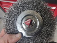
I purchase the Weiler wire wheels from McMaster Carr and always keep a spare on hand, so I had one that was not mounted to take a couple pictures for you. It is a 6" diameter wire wheel.
wire2.jpg

by 1" wide.
wire3.jpg


I use my wire wheel a lot in my shop. I go through a wheel probably every other year or so which is why I always keep a backup on hand. Same with the fine grinding wheel that I keep on the other side. When I pull the spare out to install is when I order the next one, or at least put one in my cart so it can be added to the next purchase and share freight with other items.

Hope that is helpful.
 
OP
Z

zmotorsports

ALLIANCE MEMBER
Joined
Oct 20, 2009
Messages
21,480
Location
Northern Utah
I hope everyone had a very Happy Thanksgiving and was able to enjoy it with their loved ones.


On Wednesday evening I was able to get the front axle stabbed back under the Jeep and completed.

The AGA Tools lift table was wheeled into position under the Jeep and raised to within a couple of inches of the control arms. Then a couple small tweaks of the table and axle's position and the control arms lined right up.
gear31.jpg


gear32.jpg

As I was applying anti-seize to the lower control arm bushings and newly cut down grade 8 bolts I happened to notice the thread marks hammered into the inner sleeve of the bushing from the OEM bolts. THIS is why I don't like running threads through chassis components.
gear33.jpg

This is an OEM 14mm bolt used for the lower control arm mounting. They weren't even shy with the threads and people wonder why these brackets become so easily damaged on their Jeeps.
gear34.jpg

I'm not gonna lie, the bolts didn't fall right into place like they do on the factory axle brackets as I only had about .004" clearance, so it did take just a few shakes of the axle and control arm to get everything to slide together, but they did rather easily slide through the machined weld washers and into place. Then once the control arm bolts were all installed and nuts loosely applied, I grabbed a ratchet strap to pull the axle over to the driver's side about a 1/4" to align the track bar bolt. This is the item I repaired a couple of years ago on this Jeep when I machined weld washers for both the frame side and the axle side of the track bar and they are still holding up extremely well, even through a front end impact on this Jeep.
gear35.jpg

With the suspension coils installed, control arm bolts loosely installed and track bar in place, I could now lower the lift table out of the way and finish assembly.
gear36.jpg

Axle shafts and unit bearings slid back into place and unit bearings torqued to spec.
gear37.jpg

ABS wiring installed, brakes installed and brake caliper brackets torqued to spec. then the wheel spacers were installed and torqued to spec.
gear38.jpg

Then the Jeep was lowered and shop closed up for the evening and holiday.
gear39.jpg


The front end is complete less adding gear oil and torquing all of the suspension components once it is sitting on the tires/wheels at ride height. You want to make sure that you do not tighten these rubber encapsulated (Clevite style) suspension components until the vehicle is sitting at ride height will all of the weight on it. This is referred to as having the bushings in their neutral position. If you tighten the fasteners and then set it down, it will add preload into the bushings and cause them to fail in very short order. Then need to be centered in their range of motion in order to last.

Now it's time to move on to the rear and tear it down for inspection, regear and installation of an Eaton Truetrac as well.

Thanks for looking.
 

mmsheb

Well-known member
Joined
Mar 30, 2008
Messages
365
Location
Wisconsin
Mike, in a more detailed response to your earlier question, I shot a couple of pictures of the wire wheel I use while in the shop the other night.

Here is the wire wheel mounted on my Baldor pedestal grinder. Care must be used while removing sealant and corrosion from bolt threads using a wire wheel but in a very short time it becomes more of a "feel" and takes little time. Just don't get complacent performing this action or it will bite you, trust me. :bounce:
wire1.jpg

I purchase the Weiler wire wheels from McMaster Carr and always keep a spare on hand, so I had one that was not mounted to take a couple pictures for you. It is a 6" diameter wire wheel.
wire2.jpg

by 1" wide.
wire3.jpg


I use my wire wheel a lot in my shop. I go through a wheel probably every other year or so which is why I always keep a backup on hand. Same with the fine grinding wheel that I keep on the other side. When I pull the spare out to install is when I order the next one, or at least put one in my cart so it can be added to the next purchase and share freight with other items.

Hope that is helpful.
Thank you for your follow up on the wire wheel. As always, I appreciate your very detailed information.
Mike in WI
 

PhantomEB

Well-known member
Joined
Feb 6, 2006
Messages
6,858
Location
Medicine Hat, AB, Canuckistan
Mike, between you, a few others as well my brother who’s also a Millwright, more and more my own shop is getting dialed in too.

now I got an 8 foot front main bench and should have a 5’ side bench, both will have at least 1 if not two sheets of 3/4“ plywood. Don’t really want both to be metal tops…..
 
OP
Z

zmotorsports

ALLIANCE MEMBER
Joined
Oct 20, 2009
Messages
21,480
Location
Northern Utah
Thank you for your follow up on the wire wheel. As always, I appreciate your very detailed information.
Mike in WI

Happy to provide any information I can Mike.


Mike, between you, a few others as well my brother who’s also a Millwright, more and more my own shop is getting dialed in too.

now I got an 8 foot front main bench and should have a 5’ side bench, both will have at least 1 if not two sheets of 3/4“ plywood. Don’t really want both to be metal tops…..


Thank you. Dialing in a shop takes time, but more importantly, keep in mind no two are alike as no two owners are alike. We all have different preferences on how we like to store things, how we like to work and in what order we do things in our shops.

While I "thought" I had my last shop dialed in pretty well when I first built it and moved tools and equipment in, it turns out that over the course of 25 years it morphed just enough between the added tools and equipment as well as the work itself changed somewhat, that it became a bit cumbersome in the later years. Mainly due to space constraints, but also as the equipment placement while perfect for some tasks, interfered with others.

When I was designing this shop, along with my son's help, we thought more fully through the process with one goal in mind, and that was workflow, especially where I had a dream of us doing custom work in it together. I did things like put different pieces of equipment on different circuits so they could be run simultaneously without an interruption to a breaker or one of us tripping over the other while performing various tasks.

Those little details have what has made it into my dream shop, and what I hope will provide many, many years of us working in it together as we now have another generation that will hopefully be out there with us.

I enjoy watching shop tour videos of various people and seeing how they have laid out their shops in terms of equipment and they all seem to vary, but they vary based on the tasks the owners perform the most.

I REALLY like watching the old-time home-based race shop videos when they are posted as the layouts and history of them I find very interesting. I hope someday my son and grandson can look back on our home shop and have fond memories and "feel" the history in the shop and wear in the tools and cherish those memories.
 

Bob Heine

ALLIANCE MEMBER
Joined
Oct 24, 2009
Messages
10,709
Location
Boca Raton, Florida
Just don't get complacent performing this action or it will bite you, trust me. :bounce:
wire1.jpg
Mike, I have taken a fair bit of skin off my fingertips and thumb doing that. I believe you are the one who introduced me to the Grip-on family of clamping pliers and I use the 912 L-Type Axial one to hold the bolt head. The jaws have no teeth so they don't mar the bolt head but hold it nice and tight.
Grip-on 912 L-Type Axial.jpg
 

PhantomEB

Well-known member
Joined
Feb 6, 2006
Messages
6,858
Location
Medicine Hat, AB, Canuckistan
Mike, I have taken a fair bit of skin off my fingertips and thumb doing that. I believe you are the one who introduced me to the Grip-on family of clamping pliers and I use the 912 L-Type Axial one to hold the bolt head. The jaws have no teeth so they don't mar the bolt head but hold it nice and tight.
Grip-on 912 L-Type Axial.jpg
I need me one of those, Hell I will make a little pocket on my grinder pedestal for just that!
 
To avoid these ads, REGISTER NOW!

casmurbax

Well-known member
Joined
Sep 25, 2012
Messages
2,761
Location
Wilton, NY
Mike, I have taken a fair bit of skin off my fingertips and thumb doing that. I believe you are the one who introduced me to the Grip-on family of clamping pliers and I use the 912 L-Type Axial one to hold the bolt head. The jaws have no teeth so they don't mar the bolt head but hold it nice and tight.
Grip-on 912 L-Type Axial.jpg
I bought one at the same time you did Bob, Mike was cutting something on the bandsaw when that was introduced to us. Not impossible but it is difficult to get a wire bristle out of your only hand by yourself.
 
OP
Z

zmotorsports

ALLIANCE MEMBER
Joined
Oct 20, 2009
Messages
21,480
Location
Northern Utah
Possibly referring to "Stapleton42" on YouTube?

Yes, that is the channel. The one he fairly recently posted on Ken Shrader's shop was the one I found most interesting. When they went to the old race shop where his sister and BIL now live after demo'ing the original home on the property and building a new one a few years back.

I could almost sense the history and vibe in that shop.

Some of the newer, high tech ones in large industrial complex really don't interest me as much as the modest home based race shops.
 

Chris F

Well-known member
Joined
Jul 29, 2023
Messages
90
Location
CNY
Couldn't agree more, was hoping they would've shown more of Ken's current shop, maybe another video? Loved the one with Johnny Benson's place. I think it's amazing the number of items that remain after so many years.
 

Scuderia-F1

Well-known member
Joined
Feb 9, 2011
Messages
1,198
Location
Stockholm, Sweden
Yes, that is the channel. The one he fairly recently posted on Ken Shrader's shop was the one I found most interesting. When they went to the old race shop where his sister and BIL now live after demo'ing the original home on the property and building a new one a few years back.

I could almost sense the history and vibe in that shop.

Some of the newer, high tech ones in large industrial complex really don't interest me as much as the modest home based race shops.
Make sure to also follow Mitchell’s second channel, called Stapleton 42 extra, or something like that. Lots of awesomeness that never makes it onto the more commercial mainchannel.
 
OP
Z

zmotorsports

ALLIANCE MEMBER
Joined
Oct 20, 2009
Messages
21,480
Location
Northern Utah
Couldn't agree more, was hoping they would've shown more of Ken's current shop, maybe another video? Loved the one with Johnny Benson's place. I think it's amazing the number of items that remain after so many years.

I'll have to check that one out, I think I missed that one.

Make sure to also follow Mitchell’s second channel, called Stapleton 42 extra, or something like that. Lots of awesomeness that never makes it onto the more commercial mainchannel.

Thank you Anders. I didn't know of the other channel. I started following him several years ago when he bought his older Newell coach but then when his channel's content changed, I stopped following him. I stumbled back across it again a few weeks ago and have enjoyed some of the smaller home-based race shop tours of days gone by.
 
OP
Z

zmotorsports

ALLIANCE MEMBER
Joined
Oct 20, 2009
Messages
21,480
Location
Northern Utah
I hope everyone had a great weekend and was able to spend time with their families and loved ones.

I didn't spend much time in the shop over the holiday weekend.

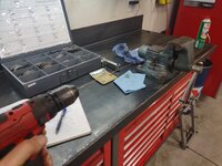
I had a small welding job to take care of that required some fine wire. I kept the .030" ER70S-6 from when I swapped out the old roll of MIG wire and kept the 15' that was in my gun. I cut it into lengths that would fit into my TIG rod holders but when I pulled one out to complete my welding job, I noticed they were curled still and made it problematic to put the cap back on as well as holding them was a bit cumbersome being curved. I remembered seeing a trick a while back about tensioning the wire with a drill motor so I gave it a shot. Here are a few that are still coiled and one that I straightened already.
wire1.jpg

One end clamped in the bench vise and the other in the drill motor and turned at low speed to add tension into the wire.
wire2.jpg

Bingo, straight as an arrow.
wire3.jpg

Several others straightened before putting back into the TIG Rod guard holders.
wire4.jpg

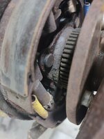
Moving on to the Jeep that I have in the shop I began tearing the rear axle down for regear and limited slip installation. I noted the dampness behind the brakes so notified the owner to let him know we'll be needing to replace the seals and bearings while we're in their. Actually, for 186k miles these have held up well an I don't think they've been out before. The left side was a bear to remove and I still haven't gotten the right side out yet it is stuck in the axle housing. My little 3 and 5 pound slide hammers won't even touch it so I have a 10 pounder coming that hopefully will do the trick.
gear41.jpg

Driver's side axle removed as well as the backing plate removed. I generally don't remove the backing plates, however, these are pretty corroded and thin so the owner provided new backing plates for installation during the regear process, so it was removed at this time.
gear45.jpg

One side down and one to go.
gear44.jpg

They were beginning the leak pretty good but not to the point of dripping gear oil yet.
gear46.jpg

While giving my arms a rest from trying to remove the passenger's side rear axle shaft, I thought I'd remove the bearing, seal and locking ring from the left axle shaft and prepare it for reassembly.
gear47.jpg


Stay tuned for more pictures to come.
 
OP
Z

zmotorsports

ALLIANCE MEMBER
Joined
Oct 20, 2009
Messages
21,480
Location
Northern Utah
Continuing on with the work on the axle shaft.

With the axle shaft on some V-locks to prevent having to chase it around the bench, I cut a slit in the lock ring with a .035" cutoff disc. Be very careful here to not go down past the ID of the lock ring as you can easily contact the axle shaft and nick the surface, thus weakening the shaft. Just cut down to within about .031"-.062" is far enough. I also like to cut at an angle. This does two things, first it keeps the cutoff disc out of the way of damaging the retainer and other parts, but secondly, by cutting at an angle it makes the lock ring spiral off when the time times with a punch.
gear48.jpg

When you are close to going through, take a cold chisel and drive it down into the small slit. This will fracture the lock ring within a strike or two.
gear49.jpg

Here you can see the fracture line down inside the cut.
gear50.jpg

Here is the second reason I cut at an angle, by tilting the chisel and striking it as close to parallel to the axle shaft as possible, it opens the lock ring at the split and it easily slides off the bearing's mating area. A couple of small strikes here moves it quickly and easily out of the way.
gear51.jpg

Out of the way to allow access to do the same to the bearing.
gear52.jpg

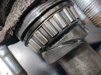
Begin by removing the cage and rollers from the bearing.
gear53.jpg

Then score a line through the bearing just like the lock ring, being extremely careful to not go through the inner race into the axle shaft.
gear54.jpg

Using the cold chisel again, strike and fracture the bearing's inner race.
gear55.jpg

And it will also easily slide out of the way.
gear56.jpg

Tilt up the axle and let all of the components slide off onto the bench.
gear57.jpg

Stay tuned for more pictures...
 
OP
Z

zmotorsports

ALLIANCE MEMBER
Joined
Oct 20, 2009
Messages
21,480
Location
Northern Utah
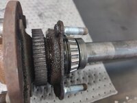
Now into the solvent tank the axle shaft and retainer go for a thorough cleaning.gear58.jpg

Both cleaned.
gear59.jpg

While the axle shaft's hub and reluctor wheel came pretty clean, the retainer is horrible.
gear60.jpg

Off to the bead blasting cabinet to remove nearly 18-years and 186k miles worth of corrosion and gunk.
gear61.jpg

That looks much better. Once the other one is to this point, I will coat both retainers with some paint before reassembling.
gear62.jpg

Before closing up the shop for the day, I thought I would hit some fasteners with some penetrant. The owner asked me if I would also replace the fuel pump and tank skid, or in the Jeep's case, the fuel tank skid is also the mounting enclosure. I thought I would do a comparison between Kroil and the Knock-Er-Loose penetrants. The bolts were tight and I doubt have ever been removed in all these years. I didn't want to break nor strip any as one is already missing holding the transfer case skid on. With the heads completely tight up against the skid, I hammed at them for a few uggha dugga's to back out a few threads on each fastener. Once the fasteners had a slight gap between the washer and the skid, I sprayed penetrant up into the threads as much as I could get access to. I did have with Kroil and half with Knock-Er-Loose to see which one works best and walked away for the day.
tank1.jpg

tank2.jpg

tank3.jpg

We'll see how well they come out, or don't.

Thanks for looking.
 

mmsheb

Well-known member
Joined
Mar 30, 2008
Messages
365
Location
Wisconsin
I’ve got a fair amount of experience in tumbling. There is no magic recipe. It varies based on what you want to do.

How I found all my equipment for cleaning/restoring was by sending test pieces to the suppliers. I gave them my expectations on what I wanted. They shipped back. If I wasn’t happy I tried another supplier till I got what I wanted.

Giant finishing in Chicago is where we landed for tumblers and media. And vixen vapor blasting for our blasting cabinets.

Even then it’s constant tweaking till you get what you want out of it.

Every material has a different recipe. It’s kind like buying a power hammer or lathe. You spend the money on the equipment. Ok your done right? Bought the best you could afford? Then you realize there’s this thing called tooling. Off you go and it seems to never end.

It 100% depends on the material and its desired finish. We have all different kinds of media, cleaning solutions etc.

I wish there was one recipe. But unfortunately it doesn’t exist.
olsenmotorsports - thank you for your comments about tumbling. I appreciate it!
Mike in WI
 
OP
Z

zmotorsports

ALLIANCE MEMBER
Joined
Oct 20, 2009
Messages
21,480
Location
Northern Utah
Waiting to see the results of the comparison… I am hoping kroil wins as I get that **** from work!

I'm trying to be neutral, but I just want the Kroil to win because that has been my "go-to" for 35+ years now and I want to continue to believe it is still at the top of the list of penetrants. :bounce: I did figure that if I was going to do a test, this fuel tank support/skid would be the best chance of a fair comparison.
 
OP
Z

zmotorsports

ALLIANCE MEMBER
Joined
Oct 20, 2009
Messages
21,480
Location
Northern Utah
Will you use your TECH Angle torque wrench to record removal torque? I would showcase that ability when I sold them but never had any feedback that it was used that way.

I wasn't planning on using anything that high tech Sterling. I just figured I could get a "feel" for how well they come out with my impact gun. They were not very cooperative before the penetrant when I was just trying to get them out a turn or two. I just wanted enough of a gap to get the penetrant in and I feared I was going to snap them off. I doubt they've ever been out until now.


Mike, I have to thank you again! I would have gotten right into the gear swap on my Jeep and realized that I had no clue how to get the dang bearings off of the axles on the rear.

They're pretty simple Keith. If you've ever done a Ford 9", they are the same process.

Some people like to use a torch (gas-ax) to remove the lock rings and bearings, but I prefer to use a die grinder as there is less chance of marring or nicking the axle shaft itself. Now I would be lying if I said I had never done them using the torch, as I have. BUT, they stink up the shop something horrible, so between the risk of hitting the axle AND the smell, I haven't used a torch in about 25 or so years now when replacing this style of bearing.


They're pretty quick to do when I'm not taking pictures. Back when I was racing I'd do these a LOT. Due to me having a hydraulic press in my shop, many times clients would just bring me their axle shafts with new bearings and seals and drop them off to replace and pick up later. I remember back in the early days at my speed shop, I'd charge $10 per axle to replace bearings. That was a day or two ago.... :unsure:
 

ntsqd

Well-known member
Joined
Jan 22, 2005
Messages
997
Location
Lower left coast
The trick that I've seen used to split those bearing lock/retainer rings that I've long wondered about was to drill most of the way thru one with a drill bit that was almost as wide as the ring, and then hit it with a chisel centered on the hole. I didn't see it done, I saw the part afterwards. Nice, clean fracture of the ring, but no idea how many hammer hits were needed.
 
OP
Z

zmotorsports

ALLIANCE MEMBER
Joined
Oct 20, 2009
Messages
21,480
Location
Northern Utah
The trick that I've seen used to split those bearing lock/retainer rings that I've long wondered about was to drill most of the way thru one with a drill bit that was almost as wide as the ring, and then hit it with a chisel centered on the hole. I didn't see it done, I saw the part afterwards. Nice, clean fracture of the ring, but no idea how many hammer hits were needed.

I've heard of that method as well, but have never tried it. This method works so well for me it's just what I stick with and has never failed me. The problem I worry about using the drill bit method, is that the point can go past the depth that I feel needs to be acquired in order for a clean fracture and I feel I can control that depth better with a zip-disc than I can a pointed drill bit. But that's just me.

Can't count how many of these I've done using this method over the past several decades, but it's been a few. :unsure:
 
OP
Z

zmotorsports

ALLIANCE MEMBER
Joined
Oct 20, 2009
Messages
21,480
Location
Northern Utah
Last night I swapped out the fuel tank skid/cradle and replaced the fuel pump on the Jeep JKU. I discovered another very handy use for the AGA Tools powertrain lift table as it makes this job much less hated, especially when the fuel tank if full. :bounce:


Lift table in position and up against the fuel tank cradle. The fasteners were all broke loose and treated with penetrant for a couple of days now. Kroil on half and Knock-Er-Loose on the other half of the fasteners. I really want to say that the Kroil kicked ***, however, I unfortunately have to report that I saw no distinct difference between the two penetrants. My 3/8" impact with extension wouldn't even touch them, so I grabbed my good ole' trusty IR Titanium 1/2" with a 18mm wobbly and removed all of the fasteners. A couple came right out without hesitation, but the majority of them still were slow to come out. At this point I think all I can say is that in this scenario, some form of penetrant was better than no penetrant at all. One thing I did notice however, was that the Kroil seemed to wick its way up the threads just a couple more threads than the Knock-Er-Loose penetrant.
tank1.jpg

Fuel tank lowered and rolled out from under the Jeep.
tank2.jpg


At this point I realized I missed my opportunity. My son had just stopped by the shop after work to visit and he had just left when I lowered the fuel tank. I instantly realized my folly. I should have asked him to wait a few minutes so he could help me lift the fuel tank out of the old cradle and reinsert it into the new one. The tank was heavy and awkward and every time I lifted one end the other just slid around and neither end was coming out of the cradle.

After screwing with it for about 15-minutes I came up with a better solution. I parked it perpendicular to the Jeep right under the rear bumper. I raised the table up to within about 2' of the rear bumper and slid a couple of prybars under the poly tank and dropped a tie-down between the tank and cradle then fished it out with a magnet.
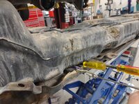
tank3.jpg

Then with it slung from either end of the tank, I lowered the table and cradle away from the tank. Even then it stuck occasionally and had to be assisted to drop away. Mainly due to a few dents in the cradle and the fact that it was packed with mud and debris which locked the two together.
tank4.jpg


With the tank out of the cradle, I cleaned off the underside of the poly tank. I didn't want to reassemble it into the new cradle with the possibility of a pebble or rock between the tank and the cradle which would wear a hole in it. I brushed the bottom of the tank off, then grabbed a wet towel and cleaned the bottom thoroughly before raising the new cradle up to capture the tank.
tank5.jpg

With the tank now married back with the cradle, it was time to tackle the fuel pump. I removed the lock ring and removed the old fuel pump.
tank6.jpg

Compared the new pump to the old.
tank7.jpg

Client supplied both a new O-ring and lock ring which was nice as these generally need replacing.
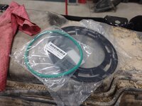
tank8.jpg

Once the mounting surface of the tank was cleaned, the new O-ring was treated with some Sil-Glyde prior to installation.
tank9.jpg

New O-ring in place.
tank10.jpg


More pictures to follow....
 
OP
Z

zmotorsports

ALLIANCE MEMBER
Joined
Oct 20, 2009
Messages
21,480
Location
Northern Utah
Continuing on with the fuel pump replacement.

Fuel pump installed and lock ring tightened. Fuel line reconnected to the pump.
tank11.jpg

With the pump replaced, lines reconnected and sitting in the new cradle, it is ready for installation back under the Jeep.
tank12.jpg

But first, I ran a tap through each of the threaded holes to clean up the threads.
tank13.jpg

With the table back under the Jeep and raised the fuel tank up into position, the bolts easily started with a finger and threaded in about half way.
tank14.jpg

All of the fasteners started.
tank15.jpg

About half of the fasteners were within easy reach with the lift table in place so they were fully tightened, then the table lowered and moved out of the way to tighten the remaining fasteners.
tank16.jpg

Now will all fasteners tightened and the lift table out of the way, the fuel lines, fill hose, and vapor lines could be reconnected.
tank17.jpg

Tank securely reattached to the Jeep.
tank19.jpg

And the front factory skid plate reinstalled.
tank18.jpg

Then cleanup began. Holy cow what a mess. I think the Jeep will weigh less now with as much dirt and debris fell from it.:ROFLMAO:
tank20.jpg


That concluded the fuel tank cradle and fuel pump replacement.

Thanks for looking.
 
To avoid these ads, REGISTER NOW!
Top Bottom