To avoid these ads, REGISTER NOW!

ZMotorsports Shop Projects 2.0

rmack898

Well-known member
Joined
Jan 23, 2007
Messages
3,192
Location
Honu Grove NE Florida
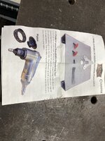
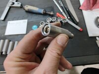
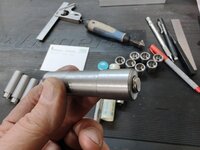
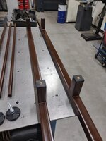
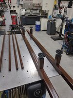
Mike, shortly after I got my chamfer tool my son bought me the Swag table for the chamfer tool and I haven’t removed the tool from the table since I got it.
The table makes chamfering smaller parts so much easier and I find myself using the tool more than I would if I didn’t have the table.
IMG_8920.jpegIMG_8921.jpeg
 
To avoid these ads, REGISTER NOW!

slodat

ALLIANCE MEMBER
Joined
Feb 6, 2010
Messages
3,682
Location
Central-ish, WA
Mike, shortly after I got my chamfer tool my son bought me the Swag table for the chamfer tool and I haven’t removed the tool from the table since I got it.
The table makes chamfering smaller parts so much easier and I find myself using the tool more than I would if I didn’t have the table.
IMG_8920.jpegIMG_8921.jpeg
I have one as well. Really handy!
 

Monza Harry

Well-known member
Joined
Dec 29, 2018
Messages
1,433
Location
Windsor ON
I finally convinced my wife that one of those chamfer tools would be the best Christmas present ever! I have played with it, but only a bit. It does seem to cut nice, but a powerhouse it ain't! I plan on a table, but after looking at the "SWAG OR" unit it doesn't appear to be an easy remove/re-install, also to my surprise they don't offer the 2"² mount. Those are both considerations my table will need to address, I am eager to see if you feel the same on these and or other "needs to be's" and your work arounds/fixes.
I plan for my table to have some kind of register from thr back with a hole for the air inlet to seat in [probably need to be height adjustable] and a saddle for part of the body to seat in as well. A toggle clamp over a "spider" hold down of some excessive nature to hold it in place! LOL! 🙄 https://www.leevalley.com/en-ca/sho...parts/45034-cam-clamp-mechanism-1-4-20-thread or something similar to this
1707188460070.png
 
Last edited:
OP
Z

zmotorsports

ALLIANCE MEMBER
Joined
Oct 20, 2009
Messages
21,439
Location
Northern Utah
@Monza Harry , I really don't have any plans for a table at this point. I can see where it may be useful and as Mac states, he hasn't removed it since. However, I don't want to give up the space for a table and I just bought it out of curiosity more than anything. I really don't have a problem using my belt/disc sander for deburring as that's what I've used for nearly 3 decades with great success. Uniformity can be a bit tricky with the belt/disc sander but after some practice it has become like second nature to keep an even chamfer going around a part. I do like the idea of the small handheld unit getting into those hard to reach areas though.

Time will tell how much I use it because I don't want to be replacing the inserts after every job as they do seem a bit small and anemic. Again, time will tell.
 
OP
Z

zmotorsports

ALLIANCE MEMBER
Joined
Oct 20, 2009
Messages
21,439
Location
Northern Utah
I was able to get some more machining done last night.

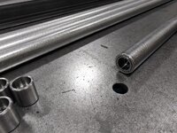
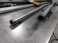
Needing these parts to go through the 2" square tubing and then protrude out the .375" distance to fit into the female parts previously machined, I thought 5" long which will be cut in half and will also compensate for the blade thickness and a little cleanup for facing cuts of about .020"-.040" and minimal waste. I grabbed a piece of 1" OD 1020 bar stock off the shelf and cut four 5" long pieces. The stop for my horizontal bandsaw that I made a couple of years ago works perfectly for repeatability in cuts.
frame11.jpg

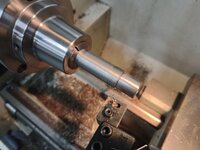
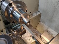
After using the 1" collet to turn half of them all down to .875", I flipped them and used a 7/8" collet to turn the other end down to the major size.
frame12.jpg

Once the outside diameter was reached, I turned down each end to .623" diameter and .375" in length.
frame13.jpg

This will allow the female parts to fit on nice and snug without being too tight or sloppy. Perfect fit.
frame15.jpg

Two down and two to go.
frame16.jpg

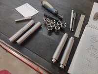
All four pieces are turned to size.
frame17.jpg

Now they are cut in half in the vertical bandsaw. Sometimes I find it easier and faster to cut in the bandsaw vs. parting off. This was one of those times where it just made more sense to line them up and cut them all in the saw before facing them to length.
frame18.jpg

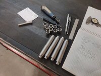
Now to face them to length.
frame19.jpg


That was where I closed up the shop last night. To be honest, the wife came home from work and was less than pleased when she walked into the shop and couldn't see across it due to the smoke from the cutting oil. She let me know that was not acceptable behavior. :oops: To be honest, I was in the zone machining and hadn't looked up from the lathe in a while and hadn't noticed the shop being full of cutting fluid smoke. :dunno:

I can't wait for spring when I can work with the shop doors open. :bounce:

Next, I will face the parts to length, drill the 7/16" through holes and counterbore for the socket head cap screw bolt heads then I should be ready for some welding operations.

Thanks for looking.

On a side note, my nephew arrived yesterday during the day and commenced mudding the walls in the attached garage. I was pleased to find him there working when I got home from work.
 
OP
Z

zmotorsports

ALLIANCE MEMBER
Joined
Oct 20, 2009
Messages
21,439
Location
Northern Utah
6B21248B-C442-42F7-B76A-0709C459927F.jpeg
I’m assuming that this sled slides in the slot on the saw table. Did you make it or was it an accessory for the saw? Never seen one that precise before, all that I’ve seen before were just a cheap miter attachment. Very nice!

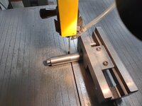
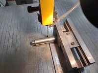
Sterling, that is actually just my small~ish (2.5")_drill vise that I use specifically on my vertical bandsaw by turning on its side or upside down for clamping round stock and cutting. If memory serves, mine is a Wilton. It's nothing special nor rides in a groove, all freehand.
 
OP
Z

zmotorsports

ALLIANCE MEMBER
Joined
Oct 20, 2009
Messages
21,439
Location
Northern Utah
Some more progress last night.

First order of the night was to cut all of the major components to length, wipe them down with acetone and prepare them for the next steps in the process.
frame21.jpg

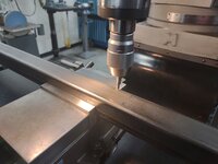
With the side rails measured, marked and clamped in the mill's vise, I found the edge of the tube and zero'd the DRO. The round tubes that will serve as the crossbars are 1" in diameter so in order to keep the top of the crossbar round tubes, flush with the tops of the side rails I will drill the through holes .500" from the top.
frame22.jpg

Progressing through the drilling process hole by hole. A few repositioning events needed to take place but all in all a pretty easy procedure to ensure the holes are all at the same dimension from the top of the rail. I also drilled some 5/16" holes through the top rails in which I will attach the wood side rails that are now holding the headboard to the footboard. The wood rails will bolt to the metal inner framework to try and keep as much of the wood aesthetics as possible.
frame23.jpg

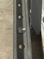
Both side rails are drilled and in need of wiping the cutting fluid off then chamfering the holes. I HATE this picture because it shows the mess in my shop with the yard cart and everything else stuffed in the shop while the garage is being worked on. It makes my shop feel so cluttered right now.
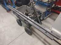
frame24.jpg

Side rails wiped down with acetone and all of the holes chamfered.
frame25.jpg

Next I shifted gears back to the lathe and started machining the OD of the through bungs that will be welded into each of these large through holes in the side rails. I was able to get a couple of them taken down to the correct OD's last night, next will be to complete the remainder and then drill holes through them with counterbores for the socket head cap screw bolt heads.
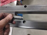
frame26.jpg


This next part I thought I'd share for those drilling deep holes on lathes. It is a technique that I learned a few years ago, however, maybe many of you already know this and I am just late to the party. :dunno:

The technique I believe is called "pecking", but don't quote me on that. It saves time and effort turning the tailstock handle as you plunge into the hole and then have to extract the bit to clear chips and reapply cutting fluid before cranking the tailstock handle all the way back in again.

The process may seem difficult but once you practice it a time or two becomes very quick and almost habitual in motion. Once you have your drill chuck and bit in the tailstock, move the entire tailstock up close to the workpiece with the tailstock threaded in nearly to the point of extracting the chuck. This keep from having to overextend the tailstock as the hole depth increases.

Once the bit is near the workpiece, move the carriage away from the head of the lathe up to the point it barely makes contact with the base of the tailstock.

Here you can see the tailstock and carriage are in light contact as there is no gap between them.
frame27.jpg

Next lock the tailstock to the ways and begin feeding the bit into the work and drilling as normal using the tailstock crank.
frame28.jpg

When you get to the point that the chips need to be cleared and more cutting fluid applied, rather than cranking the tailstock quill all the way back into the tailstock housing, merely back the crank off about a half a turn, basically just break contact with the bit's cutting end and the workpiece, then release the tailstock to bedway lock and pull the tailstock away from the workpiece. This allows quick cleaning of the chip and ability to reapply fluid to the bit.
frame29.jpg

Next, push the tailstock back towards the head of the lathe and "bump" it up against the carriage and lock the tailstock to the bed. At this point the bit's tip is not in contact with the workpiece yet and you can begin cranking it from the point you left off in the previous step. Then it is as simple as apply, rinse and repeat until the hole is drilled to depth.
frame30.jpg


One thing that aids in the "fluidity" of the motion is to ensure there is some way oil on the bedways. I generally apply a little extra by rocking the tailstock or pivoting it back slightly, squirt a bit under the leading edge of the tailstock and then push it back and forth a couple of times to distribute the way oil under the tailstock before beginning this technique. This helps the tailstock "float" in and out with ease as you are pulling it away from and back towards the carriage.

Hope that helps and I apologize if everyone already knew about this techique. It is something I only learned a few years ago and use it frequently when drilling deep holes in multiple parts as it really is a time saver.

Thanks for looking.
 
OP
Z

zmotorsports

ALLIANCE MEMBER
Joined
Oct 20, 2009
Messages
21,439
Location
Northern Utah
I didn't get much shop time last night. Took me well over an hour to get home due to idiots and aggressive driving on wet roads. People are really ******* me off lately in their driving habits. They think they are more important than anyone else on the roads and weave in/out of traffic and then cause an accident. Then as soon as that accident is passed, people hammer down and drive like idiots until they are involved and cause another one less than a half mile down the road. My hell, what is it going to take to get people to figure out that we are all trying to get somewhere and no one is more important or needs to be anywhere more than the rest of us. ******* aggressive and selfish drivers these days.

Now that's out of the way, once I FINALLY got home, bumped the heat and was able to get to work in the shop I only had enough time to knock out a couple of parts for the bed frame project.

I flipped the parts end for end in the collet chuck and took the other end down to size. I am not going after surface finish here and I'm pushing the feeds & speeds a bit as these parts will be almost completely encased inside of the square tubing. The small .623" protrusion is getting a nicer finishing pass. While the part was flipped taking the remainder to size I also bored the .625" counterbore for the socket head cap screw bolt head to fit.
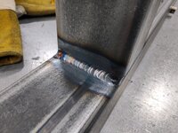
frame31.jpg

The SHCS fits in perfectly below flush. I bored the counterbore to a depth of .500" even though the head only measured about .425" tall.
frame32.jpg

Test fit of how the parts will bolt together. The long bung will we welded into the 2" square tube and the female bung will be pressed and welded into each end of each 1" round crossbar. They will bolt together like such.
frame33.jpg

Once tightened they will create a nice solid framework or assembly.
frame34.jpg

Two down and six more to go before I can start the welding process.
frame35.jpg

Thanks for looking.
 
OP
Z

zmotorsports

ALLIANCE MEMBER
Joined
Oct 20, 2009
Messages
21,439
Location
Northern Utah
Mike - very nice method on the peck drilling with the tailstock! Parts look great.

Thanks Steven. I'm not sure if that was a process that everyone already knew about and I was just a late bloomer as I only learned it a few years ago, but I thought it would be good to share regardless.

Thanks for continuing to follow along.
 
OP
Z

zmotorsports

ALLIANCE MEMBER
Joined
Oct 20, 2009
Messages
21,439
Location
Northern Utah
Finished up the machining process last night on the bedframe components.

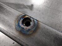
Test fit into the side rails. Fits nice and flush on the inner side where I can put a small autogenous TIG weld.
frame36.jpg

The outside has a small chamfer where I can add a little filler and still a relatively small bead.
frame37.jpg

A small amount knocked off the diameter of the head of the SHCS.
frame38.jpg

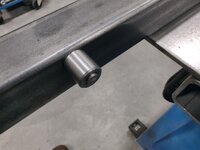
Protruding through to capture the bung which will be welded into the round crossbars.
frame39.jpg

Bung bolted in place. This sits .095" below the top surface of the square tubing which is the wall thickness of the round tubing.
frame40.jpg

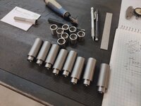
All of the components machined and laid out for the next step.
frame41.jpg


That should complete the machining process. Next, I can prep the tubing for the welding process to commence. Before I begin welding however, I need to clean up the lathe, mill and floor as it is driving me bonkers walking on all these metal chips/shavings.

Thanks for looking.
 

slodat

ALLIANCE MEMBER
Joined
Feb 6, 2010
Messages
3,682
Location
Central-ish, WA
Thanks Steven. I'm not sure if that was a process that everyone already knew about and I was just a late bloomer as I only learned it a few years ago, but I thought it would be good to share regardless.

Thanks for continuing to follow along.
The only reason I’m familiar with it is CNC peck cycles. Seeing you use the same concept in a manual machine is awesome and probably new to some folks. I like your method of sliding the tail stock for quick chip evacuation. Good stuff! Always enjoy your thread! Thanks for sharing it all with us!
 

Monza Harry

Well-known member
Joined
Dec 29, 2018
Messages
1,433
Location
Windsor ON
Mike there is an attachment to facilitate the quick retracting of he tailstock quill. My "Google" search however did not find the one I remember! I will share what my search did reveal :
It did reveal lots of carriage mount and complete replacement tailstocks, I feel that a carriage mount drill chuck would be a better choice in my experience. Most of my lathe experience is with 100-200# tailstocks. [Mine is likely 80# and is only a 15-30] Those would typically be modified for an air cushion/float to make multiple moves per hour so much easier.
I did turn this up in my search for the quick retract, [Google seems to return results with any of the keywords you use, in this case "tailstock attachment"] I was going to make one but at these prices I'll likely just buy if $$$ permits:
NEW IMPROVED TAPER TURNING ATTACHMENT WITH REVOLVING LIVE CENTER FOR LATHE MACHINE-METRIC (MORSE TAPER 4MT) https://www.amazon.com/dp/B09PJF4GHL?tag=atomicindus08-20
This will allow for a little adjustment of the vertical wear that usually happens over time. These allow taper turning without adjusting the tailstock from center (by rotating from pure horizontal plane). Harry
 
Last edited:

bigdave_185

Well-known member
Joined
Feb 14, 2021
Messages
439
Location
Utah
I don’t know if I missed the portion of the description of the new bed….. lots of these new beds are designed to be used with out a box spring. Is the existing bed pretty tall? I know my wife like our bed life 5’ tall. I’m not tall by any definition but climbing into the bed is a PIA. If I took our box spring out it would be much more manageable in height.
 
OP
Z

zmotorsports

ALLIANCE MEMBER
Joined
Oct 20, 2009
Messages
21,439
Location
Northern Utah
I don't know about others, but we had a beautiful weekend here along the Wasatch Front, other than being bitter cold. Blue skies and crisp, clean air this weekend after last week's storms rolled through. Made me almost want to get my patio furniture out and have coffee on the deck, almost.

After a few cups of coffee Saturday morning I headed out to the shop to service the wife's daily driver.

With the Acura racked, tires removed I drained the engine oil and inspected the undercarriage.
acura1.jpg

Replaced the oil filter and wiped down the passenger side lower control arm which seems to get a few drips of oil on it every time I remove the filter.
acrua2.jpg

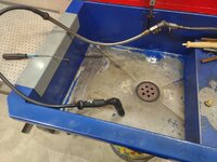
Next I installed my new solvent brush that arrived last week. The hose that runs from the flexible steel line to the brush had cracked and broken a few weeks back and after searching for a new hose I found it was almost cheaper to order a brush along with the hose as a package. I have seen a few people use these angled solvent brushes and I have never used one so I thought I'd give it a try as it seemed to provide a bit more ergonomic comfort, at least that's what I thought. I only used it for a short while but wasn't "feeling" it.
brush1.jpg

Ended up putting my old straight brush back on after using the angled one for a while. Turns out I didn't care for it nearly as much. Wonder if anyone else has tried the angled one and if they like them or not. Maybe it's just me.
brush2.jpg

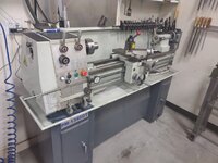
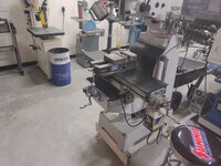
Then after finishing the wife's car, running a vacuum through it, I froze my **** of by taking it to the car wash for a wash job so the wife could have a clean car to start out her week. Afterwards, I focused on cleaning up the lathe and mill from the mess I made machining the parts for the bedframe.
machine1.jpg

machne2.jpg


Thanks for looking.
 
OP
Z

zmotorsports

ALLIANCE MEMBER
Joined
Oct 20, 2009
Messages
21,439
Location
Northern Utah
Once I got the shop clean, I turned my attention back to project at hand.

I grabbed my DA and some 60-grit sandpaper and ran it over all of the parts then gave them a wiping with acetone.
frame42.jpg

Next, I pressed the female bungs into the ends of the round crossbars.
frame43.jpg

And proceeded to weld each of them in.
frame44.jpg

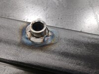
I then installed four of the through bungs and began tacking and welding them into place in the side rails. I was able to autogenous weld them so as not to build up any height with bead profile and allow everything to fit together nice and tight without any grinding or finish work.
frame45.jpg

One side rail completed other than the legs.
frame46.jpg

Test fitment of one of the crossbars. Perfect fit.
frame47.jpg

And in the exact plane I was shooting for. By centering the hole .500" from the top surface, the 1" OD round tubes sit flush with the side rails.
frame48.jpg


Thanks for looking.
 
To avoid these ads, REGISTER NOW!

Jgaz

Well-known member
Joined
Dec 16, 2016
Messages
1,689
Location
AZ
I don't know about others, but we had a beautiful weekend here along the Wasatch Front, other than being bitter cold. Blue skies and crisp, clean air this weekend after last week's storms rolled through. Made me almost want to get my patio furniture out and have coffee on the deck, almost.

After a few cups of coffee Saturday morning I headed out to the shop to service the wife's daily driver.

With the Acura racked, tires removed I drained the engine oil and inspected the undercarriage.
acura1.jpg

Replaced the oil filter and wiped down the passenger side lower control arm which seems to get a few drips of oil on it every time I remove the filter.
acrua2.jpg

Next I installed my new solvent brush that arrived last week. The hose that runs from the flexible steel line to the brush had cracked and broken a few weeks back and after searching for a new hose I found it was almost cheaper to order a brush along with the hose as a package. I have seen a few people use these angled solvent brushes and I have never used one so I thought I'd give it a try as it seemed to provide a bit more ergonomic comfort, at least that's what I thought. I only used it for a short while but wasn't "feeling" it.
brush1.jpg

Ended up putting my old straight brush back on after using the angled one for a while. Turns out I didn't care for it nearly as much. Wonder if anyone else has tried the angled one and if they like them or not. Maybe it's just me.
brush2.jpg

Then after finishing the wife's car, running a vacuum through it, I froze my **** of by taking it to the car wash for a wash job so the wife could have a clean car to start out her week. Afterwards, I focused on cleaning up the lathe and mill from the mess I made machining the parts for the bedframe.
machine1.jpg

machne2.jpg


Thanks for looking.
DANG! When you clean a machine you aren’t playing around!
Edit: Love the tig torch holder in your bed frame post.
 
OP
Z

zmotorsports

ALLIANCE MEMBER
Joined
Oct 20, 2009
Messages
21,439
Location
Northern Utah
DANG! When you clean a machine you aren’t playing around!
Edit: Love the tig torch holder in your bed frame post.

Thank you. I find it easier to clean the equipment after every job vs. letting the mess build to my breaking point. Takes mere minutes to clean the machines, then sweep the floor and I can focus on the work again rather then the mess.

The piston TIG torch holder was a project I did about 5 or 6 years ago shortly after moving into the new shop. I think I posted it in this thread when I actually made it.
 

MadeByMiller

Well-known member
Joined
Dec 29, 2018
Messages
1,230
Location
Rapid City, SD
Mike, the bed frame is coming together so nicely. It's satisfying to watch the results of your experience and knowledge come together on details like that last photo. Thank you for sharing!
 
OP
Z

zmotorsports

ALLIANCE MEMBER
Joined
Oct 20, 2009
Messages
21,439
Location
Northern Utah
Mike, the bed frame is coming together so nicely. It's satisfying to watch the results of your experience and knowledge come together on details like that last photo. Thank you for sharing!

Top Notch Work As Always Mike


Jason


Thanks guys. For an insignificant project and one made mostly of materials I had on hand, I am pretty pleased with the way it has turned out.

Just a bit more welding, then I can slap a coat of paint on it, carry the pieces into the house, assemble it and call it done. For paint I just picked up some rattle can espresso satin finish Rustoleum 2X paint.
 
OP
Z

zmotorsports

ALLIANCE MEMBER
Joined
Oct 20, 2009
Messages
21,439
Location
Northern Utah
Completed all of the final welding last night.

Flipped the side rails over and laid down autogenous welds on the exterior of the rails. I tried to keep the bead profile as small as possible so the wood siding can lay flat up against them without having to grind. I think this will work perfectly.
frame51.jpg

All four on one rail completed.
frame52.jpg

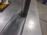
On the next side rail I swapped my tungsten over to 1/16" and that seemed to be able to keep the bead profile even smaller. Here I just started and ended up about a quarter of the way around. I did each bung the same amount, then came back and did another section and continued until I was all the way around each bung before flipping and doing the outside. The inside was a bit more awkward because of having to work around the protrusion, but the outside I was able to get in one shot around.
frame53.jpg

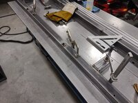
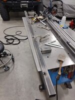
Clamped to the table and the legs positioned for tacking.
frame54.jpg

Once all corners were tacked I went back and began welding the legs on.
frame55.jpg

Making progress on the first side rail's legs.
frame56.jpg

One side rail completed and working on the second side rail's legs.
frame57.jpg

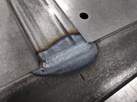
One of the leg welds.
frame58.jpg

More leg welds.
frame59.jpg

Legs completed.
frame60.jpg


A few more pictures to come....
 
OP
Z

zmotorsports

ALLIANCE MEMBER
Joined
Oct 20, 2009
Messages
21,439
Location
Northern Utah
Continuing on with the last of the pictures from last night's work.

A couple more weld closeups of the legs.
frame61.jpg

frame62.jpg

The threaded plastic supports and legs at the ready as well as the paint that I'll use. This should match the wood somewhat close, not that it's necessary as once it is assembled it won't be visible. But at least I'll know it is painted to a close wood colored match. ;)
frame63.jpg

By this time it was dark outside and I missed the opportunity to paint them so I performed a thorough shop cleaning before the wife arrived home from work. This area has been a mess for the past week and it's nice to see it clean again.
shop1.jpg

shop2.jpg

And just before closing up shop for the evening I gave all of the parts a quick wipe with Wax & Grease Remover so they are ready to paint.
shop3.jpg


Thanks for looking.
 
OP
Z

zmotorsports

ALLIANCE MEMBER
Joined
Oct 20, 2009
Messages
21,439
Location
Northern Utah
the Patients and attention to details is always above and beyond ! On many occasions in my shop I say to myself “ would Mike leave that “. lol. Sometimes I go back and make it better and sometimes I’m just too lazy.

Thank you, that is very flattering. I appreciate the comments and for you taking the time to continue to follow along.

I wanted to add that "cool" factor to this project, plus I must admit, I was jonesing to use the lathe and mill. :ROFLMAO:

And if I'm being honest, sometimes I have to go back and redo my own work, so I'm far from perfect myself. More of a work in progress to be honest. :unsure:
 

bigdave_185

Well-known member
Joined
Feb 14, 2021
Messages
439
Location
Utah
Noted your shop garage full, I almost forgot about the main house garage, epoxy floor, finished drywall and such? This weeks weather has been amazing!
 
OP
Z

zmotorsports

ALLIANCE MEMBER
Joined
Oct 20, 2009
Messages
21,439
Location
Northern Utah
Noted your shop garage full, I almost forgot about the main house garage, epoxy floor, finished drywall and such? This weeks weather has been amazing!

Dave, yes, the contents of the attached garage are stuffed in the shop right now as I am having it finished. Pictures and plans are posted on my shop build thread from what I've done so far. My nephew just started on the walls last week so there's not much more to report other than what I posted over on the other thread.

Agreed, the weather has been nice this week. A little cool but nice nonetheless and no snow. :thumbup:
 
OP
Z

zmotorsports

ALLIANCE MEMBER
Joined
Oct 20, 2009
Messages
21,439
Location
Northern Utah
I was able to get home and paint all of the components last night before I lost my daylight.

Crossbars painted, allowed to dry, rolled 180-degrees and finished painting.
frame64.jpg

The carriage bolts that will hold the original wood to the outside of the side rails were bead blasted and poked into a piece of cardboard for paint.
frame65.jpg

Carriage bolts painted. However, after painting I decided the markings were too contrasted so I will be knocking the markings off, bead blasting and repainting. I had hoped the marking wouldn't be very noticeable after paint but that's not the case. There are about the only pieces that will be visible so I should have addressed the markings beforehand.
frame66.jpg

All of the parts dry enough to move back into the shop and allowed to fully dry.
frame67.jpg

Threaded inserts installed into the legs.
frame68.jpg

And the 3" diameter feet threaded into the legs.
frame69.jpg


Other than the carriage bolts and final assembly in the house that pretty much completed another project. Took me a bit longer than I expected but I'm pleased with how it turned out, as long as my measurements were accurate and it actually fits anyways. :unsure:

Thanks for looking.
 

SilverJimmy

Well-known member
Joined
Apr 14, 2012
Messages
1,643
Location
Prescott/Flagstaff, AZ
I’ve taken carriage bolts to my belt grinder and made them into almost a flathead before. I like how they look, not so utilitarian.
CD2CE2C9-2502-47B4-96E6-AA56D769C42A.jpeg
I bet after paint they’d be nearly invisible. Very cool project. Sad to think about, but bed frames used to be built this stout back when real craftsmanship and product longevity were valued.
 
To avoid these ads, REGISTER NOW!
Top Bottom