To avoid these ads, REGISTER NOW!

E Heat circuit breaker getting hot?

OP
6

600SL

Well-known member
Joined
Apr 26, 2012
Messages
1,794
Location
Connecticut
1769377186006.png
OP needs to look at what he has inside the unit to figure out what size feeder(s) to run. A single to the unit can be run IF internally, it separates the circuits to be below the 60A limit.

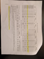
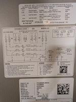
The way I read the label in post #4 it gets broken up as 60A to L1/L2 and 25A to L3/L4?
 
To avoid these ads, REGISTER NOW!

mm08822

Well-known member
Joined
Jan 13, 2012
Messages
6,004
Location
NJ
The way I read the label in post #4 it gets broken up as 60A to L1/L2 and 25A to L3/L4?
I think so............personally, that's a stupid label.

Did somebody jump the 2 circuits together in the unit??? HMMMM??? That's the only way you should be pulling 60A right now.......:headscrat
 
OP
6

600SL

Well-known member
Joined
Apr 26, 2012
Messages
1,794
Location
Connecticut
If it's in-site (and nmt 50') of the panel then not extra disco needed.

I asked mods to combine these 2 threads.

I'm only about 10' away. That will greatly simplify things. I cant seem to find out who the Moderator is?
 
OP
6

600SL

Well-known member
Joined
Apr 26, 2012
Messages
1,794
Location
Connecticut
I think so............personally, that's a stupid label.

Did somebody jump the 2 circuits together in the unit??? HMMMM??? That's the only way you should be pulling 60A right now.......:headscrat

The label gives two scenario for single and dual input. With the single input its 80A does to L1/L2. So I ASSUME that jumping them together is standard procedure but not shown on the schematic, perhaps more details in the installation manual. I will see if I can find that.
 

mm08822

Well-known member
Joined
Jan 13, 2012
Messages
6,004
Location
NJ
The label gives two scenario for single and dual input. With the single input its 80A does to L1/L2. So I ASSUME that jumping them together is standard procedure but not shown on the schematic, perhaps more details in the installation manual. I will see if I can find that.
But apparently not in the US as @Stuff noted with reference to NEC 424.......
 

wyliesdiesels

Well-known member
Joined
Aug 14, 2012
Messages
20,038
Location
Modesto, CA
I have a heat pump system that I have just found out needs to have the wiring up sized. Currently it has a 15KW E-heated on a 60Amp circuit 8ga wire, with a 60A disconnect at the indoor unit. Plan is to upgrade to 6ga wire with 70 or 80 amp CB. One question I have is do I need a disconnect at the indoor unit if I the CB panel is 10' away from it and in sight of the indoor unit.

for a 15kW load you will need ~78a rated wire so #6 is too small. you will need #4
 
OP
6

600SL

Well-known member
Joined
Apr 26, 2012
Messages
1,794
Location
Connecticut
But apparently not in the US as @Stuff noted with reference to NEC 424.......

the installation manual for the air handler says nothing. The installation manual for the heater says next to nothing but gives a better data sheet. Funny thing is the label in post #4 states that single phase heaters are shown wired for single supply circuit. But the manual states in note 3 that a special kit is required to convert the 15KW and 20KW heaters to single point wiring.

In my view it appears that the system is running in single circuit mode based on the current of 60A and was running with an inadequate 60A CB and wiring.

So is the consensus that I need one 60 amp and one 25 amp circuit or can i do a single 80 amp circuit. Both options **** for two different reasons. Single 80 amp is the more expensive option the 2 smaller circuit require me to find more room in my CB box which is currently at the limit.

1769381732219.png
 

wyliesdiesels

Well-known member
Joined
Aug 14, 2012
Messages
20,038
Location
Modesto, CA
the installation manual for the air handler says nothing. The installation manual for the heater says next to nothing but gives a better data sheet. Funny thing is the label in post #4 states that single phase heaters are shown wired for single supply circuit. But the manual states in note 3 that a special kit is required to convert the 15KW and 20KW heaters to single point wiring.

In my view it appears that the system is running in single circuit mode based on the current of 60A and was running with an inadequate 60A CB and wiring.

So is the consensus that I need one 60 amp and one 25 amp circuit or can i do a single 80 amp circuit. Both options **** for two different reasons. Single 80 amp is the more expensive option the 2 smaller circuit require me to find more room in my CB box which is currently at the limit.

Have you opened up the unit to see how its wired? this is the first step
 

PCustoms

Well-known member
Joined
Jul 23, 2011
Messages
23,209
Location
VT
Lots of stuff to figure out here but I sure as hell would not be running it on an 80A breaker on #8, especially if it seems to be drawing more then normal/unbalanced.
 

PCustoms

Well-known member
Joined
Jul 23, 2011
Messages
23,209
Location
VT
the wire is too small for the load to begin with

Yep, this is a grade "A" CF.

My guess is isn't been running on partial power for a few years OK and just kicked into high gear, which started the whole issue.


One thing I haven't seen brought up is what is the buss rated for in that breaker position?
 

mm08822

Well-known member
Joined
Jan 13, 2012
Messages
6,004
Location
NJ
If one feed is the easier fix at your main panel, then this could be a breakout box at the unit to correctly provide the 2 power circuits of 60/25......
1769383550579.png
Seems like the original install was not done to code and you have been flying just under the radar of 60A. That 60A cb would be tripping if your location was seeing 240 - 245v.
 
OP
6

600SL

Well-known member
Joined
Apr 26, 2012
Messages
1,794
Location
Connecticut
Have you opened up the unit to see how its wired? this is the first step
I did open it up once and found that opening it while it was running was not a good idea because it sucked the insulation right off the panel when I opened it. What I could see at the time didn't make much sense in the short amount of time I had. I know I can figure it out with some time but with the temps at 2° this morning. I elected to put it back together and get things running.
 
OP
6

600SL

Well-known member
Joined
Apr 26, 2012
Messages
1,794
Location
Connecticut
Lots of stuff to figure out here but I sure as hell would not be running it on an 80A breaker on #8, especially if it seems to be drawing more then normal/unbalanced.

It is now drawing normal and balanced current. I will risk it over freezing to death.
 

mm08822

Well-known member
Joined
Jan 13, 2012
Messages
6,004
Location
NJ
I did open it up once and found that opening it while it was running was not a good idea because it sucked the insulation right off the panel when I opened it. What I could see at the time didn't make much sense in the short amount of time I had. I know I can figure it out with some time but with the temps at 2° this morning. I elected to put it back together and get things running.
Ok, but now you want answers and we need info to figure out what is actually in place. Shut the cb of for 5 mins and break out the Polaroid.
 
OP
6

600SL

Well-known member
Joined
Apr 26, 2012
Messages
1,794
Location
Connecticut
If one feed is the easier fix at your main panel, then this could be a breakout box at the unit to correctly provide the 2 power circuits of 60/25......
1769383550579.png
Seems like the original install was not done to code and you have been flying just under the radar of 60A. That 60A cb would be tripping if your location was seeing 240 - 245v.
Pretty much a standard sub panel. That one way out.
 

PCustoms

Well-known member
Joined
Jul 23, 2011
Messages
23,209
Location
VT
It is now drawing normal and balanced current. I will risk it over freezing to death.

You'll be plenty warm when the place catches fire....

Seriously, throwing in a bigger fuse/breaker without diagnosing "why" or ensuring the rest of the equipment can handle it is exactly how things go south.

Good luck
 
Last edited:
To avoid these ads, REGISTER NOW!

wyliesdiesels

Well-known member
Joined
Aug 14, 2012
Messages
20,038
Location
Modesto, CA
Lots of stuff to figure out here but I sure as hell would not be running it on an 80A breaker on #8, especially if it seems to be drawing more then normal/unbalanced.

the load with dual heaters is only 69.9a, though the min circuit ampacity calc (83.4a) doesnt make sense. should be 87.4a

but yeah i wouldnt run 70a on #8
 
Last edited:

wyliesdiesels

Well-known member
Joined
Aug 14, 2012
Messages
20,038
Location
Modesto, CA
I did open it up once and found that opening it while it was running was not a good idea because it sucked the insulation right off the panel when I opened it. What I could see at the time didn't make much sense in the short amount of time I had. I know I can figure it out with some time but with the temps at 2° this morning. I elected to put it back together and get things running.
yeah you arent supposed to open it while running lol :lol_hitti:Violent:
 
OP
6

600SL

Well-known member
Joined
Apr 26, 2012
Messages
1,794
Location
Connecticut
since the other thread was deleted while i was responding...


the load with dual heaters is only 69.9a, though the min circuit ampacity calc (83.4a) doesnt make sense. should be 87.4a

but yeah i wouldnt run 70a on #8
the load with dual heater is 59.9. Its clearer with the data sheet in post 47. Or if you blow up the label.
 

wyliesdiesels

Well-known member
Joined
Aug 14, 2012
Messages
20,038
Location
Modesto, CA
the load with dual heater is 59.9. Its clearer with the data sheet in post 47. Or if you blow up the label.
aww ok that makes more sense.

59.9 x 1.25 = 74.9 + 8.5 (blower motor) = 83.4a min circuit amps

so it should be on #4 wire with a 90a breaker if running dual mode
 
OP
6

600SL

Well-known member
Joined
Apr 26, 2012
Messages
1,794
Location
Connecticut
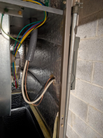
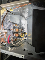
Well here are pictures of it. I would have to spend a day with the panel off to figure out whats going on.

line comes in here:
1769385323909.png

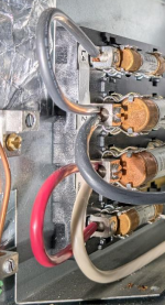
Then to these fuses. My guess is the black and red loops are what makes it a single circuit input.
1769385397339.png

Exits the fuse box here
1769385499377.png

Control Board
1769385562486.png
 
OP
6

600SL

Well-known member
Joined
Apr 26, 2012
Messages
1,794
Location
Connecticut
You'll be plenty warm when the place catches fire....

Seriously, throwing in a bigger fuse/breaker without diagnosing "why" or ensuring the rest of the equipment can handle it is exactly how thingt goe south.

Good luck

Well I do believe I have diagnosed why, The breaker is too small and yes so is the wiring. Based on me knowing the current is in bounds I will assume the risk of wire sized for 55A to carry 60A intermittently for the next few nights.
 

BurtEggley

Well-known member
Joined
Oct 8, 2024
Messages
883
I could be mistaken but I think that the chart (have to open it and rotate it) is saying that if a single set of breakers is used between 208V and 240V then one needs wire gauge and two breakers rated between 80 amps and 90 amps that can carry L1, L2, L3, L4. But if one uses four breakers, one set can be between 50 and 60 amps for L1, L2 and the other set for L3, L4 should be between 25 amps and 25 amps. I only see one pair of wires coming to the unit in the photos so it sounds like it needs to be wired between 80 and 90 amps since only one set of wires is carrying both loads L1, L2 and L3, L4. The alternative is to put in 4 breakers and run a smaller gauge wire.
 
OP
6

600SL

Well-known member
Joined
Apr 26, 2012
Messages
1,794
Location
Connecticut
While on the subject, I recall asking about using #8 wire with a 60A circuit. Both the contractor and my inspector agreed that they allow an exception for #8 with a 60A circuit because no one makes a 55A breaker. Is that just my local code or all over.
 

mike93lx

ALLIANCE MEMBER
Joined
Dec 9, 2013
Messages
37,720
Location
Richmond, VA
While on the subject, I recall asking about using #8 wire with a 60A circuit. Both the contractor and my inspector agreed that they allow an exception for #8 with a 60A circuit because no one makes a 55A breaker. Is that just my local code or all over.
That only applies when the load is below 55a
 

BurtEggley

Well-known member
Joined
Oct 8, 2024
Messages
883
So the way I read the label you have 2 options

A
Put in an 80 - 90 amp circuit with two breakers and pull L1, L2, L3 and L4 off that circuit at the destination.

B
Put in two circuits.
One for 50 - 60 amps for L1, L2
One for 25 - 25 amps for L3, L4

How many breakers do you have in the panel dedicated to L1, L2, L3 and L4?
 

mm08822

Well-known member
Joined
Jan 13, 2012
Messages
6,004
Location
NJ
Well I do believe I have diagnosed why, The breaker is too small and yes so is the wiring. Based on me knowing the current is in bounds I will assume the risk of wire sized for 55A to carry 60A intermittently for the next few nights.
And also is considered a continuous load and should be using conductors rated at 125%.
 

mm08822

Well-known member
Joined
Jan 13, 2012
Messages
6,004
Location
NJ
I could be mistaken but I think that the chart (have to open it and rotate it) is saying that if a single set of breakers is used between 208V and 240V then one needs wire gauge and two breakers rated between 80 amps and 90 amps that can carry L1, L2, L3, L4. But if one uses four breakers, one set can be between 50 and 60 amps for L1, L2 and the other set for L3, L4 should be between 25 amps and 25 amps. I only see one pair of wires coming to the unit in the photos so it sounds like it needs to be wired between 80 and 90 amps since only one set of wires is carrying both loads L1, L2 and L3, L4. The alternative is to put in 4 breakers and run a smaller gauge wire.
Only in Canada for the 80/90A.
NEC 424.22B says ckts are limited to 60A in US either externally or internally configured. OP's unit has 2 conductors under a lug to feed both sets of fuses which is violating the UL listing of the fuse holders. That's why I suggest the small sub-panel just outside of the air handler. Run 2 circuits into the unit and connect to each fuseholder with a dedicated circuit.
 

PCustoms

Well-known member
Joined
Jul 23, 2011
Messages
23,209
Location
VT
OP's unit has 2 conductors under a lug to feed both sets of fuses which is violating the UL listing of the fuse holders.

So what jumper can he pull to get this back to "normal"?

Note: I'm not sure if the wire/breaker combo is adequate even with the jumper(s) removed
 
OP
6

600SL

Well-known member
Joined
Apr 26, 2012
Messages
1,794
Location
Connecticut
That only applies when the load is below 55a
Normally for such circuits the load would be below 55a. Its only in this case that it happens to be 60a because someone f up. But if I go with two circuit system I would like to leave my #8 in place with a 60a cb and add a #10 with a 25a CB. Those would be running at 40a and 20a respectively.
 
To avoid these ads, REGISTER NOW!
Top Bottom