To avoid these ads, REGISTER NOW!

Latest fab. project - downhill racer

OP
J

Jeff Ivers

Well-known member
Joined
Apr 9, 2010
Messages
2,561
Location
Oklahoma
Wow, I can't imagine doing a 34' boat! I don't particularly like working with fiberglass, either. The biggest job I have done is the restoration of a 67 Lotus Elan, including flairing the fenders.

Really cool but that makes me itch. I had a 34' wooden boat that I covered in fiberglass. That made me lose all interest for life in it.

Can't wait to see the final product.
 
To avoid these ads, REGISTER NOW!
OP
J

Jeff Ivers

Well-known member
Joined
Apr 9, 2010
Messages
2,561
Location
Oklahoma
Borrowed Ideas Racing update:

The race was held Saturday, 9/24/2011. We made the race and ran in all the heats allowed. We did not win, but were quite a ways above last place.
We had some technical difficulty, but nothing that can't be solved by next year.

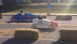
starting line.jpg
This is my grandson on the starting ramp (blue car).

Unfortunately I ran out of time. I was painting the body at 2:00 am the day of the race checkin and had to quit working on trying to smooth the body with filler.
 
Last edited:

bmxr4life87

Well-known member
Joined
Mar 21, 2009
Messages
872
Location
Bixby Oklahoma
Jeff it looks like you are a true craftsman. If you need any help give me a shout I'm only a few minutes awa from you in west tulsa
 

willymakeit

Well-known member
Joined
Apr 27, 2009
Messages
1,244
Location
Springfield Mo.
As noted that looks like fun. Im in Tulsa thru the week all the time. I will try to make it to Sand Springs or Edmond to watch. Good luck.
 

Jim Stabe

Well-known member
Joined
Feb 18, 2009
Messages
801
Location
San Diego, Ca
You mentioned that rules allowed a max car weight of 177 lbs, did you add ballast? Extra weight should make it faster - also harder to steer/stop.
 
OP
J

Jeff Ivers

Well-known member
Joined
Apr 9, 2010
Messages
2,561
Location
Oklahoma
That was one of the things I did not do well - this year. I never came up with a way to weigh the car and so erred on the light side. I did add some ballast on race day, but we were still under the allowable weight. That is on my to-do list for next year! How about posting some pictures of that MG you're building?

You mentioned that rules allowed a max car weight of 177 lbs, did you add ballast? Extra weight should make it faster - also harder to steer/stop.
 

Nighttrain

Well-known member
Joined
Aug 6, 2009
Messages
2,682
Location
Dripping Springs, Tx
I wonder if you can add a cloth type cover over the drive and fill in the cockpit for more airstream and less drag? Something just for your grandsons head to pop out of. Looks like the other car has zero open cockpit. Car really turned out nice.
 

Travis E.

Well-known member
Joined
Apr 20, 2010
Messages
214
Location
Newhall Ca.
Congratulations on a successful race.
With talk about adding more weight I have to add that aero will have a much bigger effect than weight depending on the length of the course. A wheel cover or disc to cover the spokes of the wheel will go a long way. But, most important is that you guys are having fun and spening time together.
 
OP
J

Jeff Ivers

Well-known member
Joined
Apr 9, 2010
Messages
2,561
Location
Oklahoma
I would like to add a clear cockpit cover for next year. Anyone have any tips on doing so as a DIY project?

I wonder if you can add a cloth type cover over the drive and fill in the cockpit for more airstream and less drag? Something just for your grandsons head to pop out of. Looks like the other car has zero open cockpit. Car really turned out nice.
 
OP
J

Jeff Ivers

Well-known member
Joined
Apr 9, 2010
Messages
2,561
Location
Oklahoma
Wheel covers are something else I would like to do. Anyone have any tips on how to DIY construct them?

Congratulations on a successful race.
With talk about adding more weight I have to add that aero will have a much bigger effect than weight depending on the length of the course. A wheel cover or disc to cover the spokes of the wheel will go a long way. But, most important is that you guys are having fun and spening time together.
 

Travis E.

Well-known member
Joined
Apr 20, 2010
Messages
214
Location
Newhall Ca.
Wheel covers are something else I would like to do. Anyone have any tips on how to DIY construct them?

I made them for my last soap box car. They greatly improved my top speed on all courses we raced on.
Here is how I made the mold or template to do mine.
I figured out the angle I needed to go from the hub to the inside of the rim. I then cut thin pieces of wood and stacked them to create a round steped shape and glued them together. When i had the basic size I sanded and filled to get a smooth appearance. After my template was done I made my wheel covers out of fiberglass one at a time.
 
OP
J

Jeff Ivers

Well-known member
Joined
Apr 9, 2010
Messages
2,561
Location
Oklahoma
Travis,

Good idea! Thanks for the tip. Did you cover one or both sides of the wheel?

I made them for my last soap box car. They greatly improved my top speed on all courses we raced on.
Here is how I made the mold or template to do mine.
I figured out the angle I needed to go from the hub to the inside of the rim. I then cut thin pieces of wood and stacked them to create a round steped shape and glued them together. When i had the basic size I sanded and filled to get a smooth appearance. After my template was done I made my wheel covers out of fiberglass one at a time.
 
OP
J

Jeff Ivers

Well-known member
Joined
Apr 9, 2010
Messages
2,561
Location
Oklahoma
2012 Update - Season 2 - Race Day 9/22/2012

I have spent the last several weeks working to get the downhill racer ready for this season.

First a recap of what worked and where we needed to improve:

1 - The brakes worked, without shudder. However, my grandson had some difficulty applying enough pressure.
2 - I fabbed the rear axle by welding a purchased stub axle onto a washer and then welding that to the end of a square tube axle. The stub axle weld (inside the square tube) failed, allowing the wheel to angle in at the top and creating drag.
3 - When coming off the starting ramp the first time, my grandson cocked the steering, leading to the bending of the spindle assembly. We were able to straighten it at the track.
4 - Ran out of time on the body - we weren't pretty enough.
5- I couldn't find the kind of seat I wanted, so made a padded bottom and back.
6 - I didn't have a way to weigh the car and we were under weight, reducing top speed.

rear axle 1.jpg

To make the rear axle stronger, I inserted a length of 1/2" rod into a 3/4" tube and welded it in place. This assembly was inserted into the 1" axle tube on the chassis and welded into place. The rod was then threaded and polished to the correct diameter to allow installation of the wheels. In the process of doing this, I narrowed the track by 16".

front spindle 1.jpg
front spindle 3.jpg

The front track was narrowed by 16". The front spindles were rebuilt with heavier metal and reinforcement to make them stronger.

seat.jpg
seat bracket.jpg

My son and daughter-in-law found an IKEA seat that seemed ideal for the task. The second picture shows the fabricated bracket.
 
OP
J

Jeff Ivers

Well-known member
Joined
Apr 9, 2010
Messages
2,561
Location
Oklahoma
Season 2 update, part 2

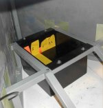
weight box 1.jpg

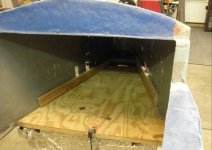
I fabbed a metal box to fit in the back of the car that weighs 17 pounds. In this, I will insert additional plates to get the car up to the allowable weight.

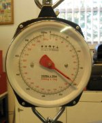
chassis weigh 1.jpg
chassis weigh 3.jpg

A spring scale has allowed me to weigh the chassis and determine we are at 112 pounds, not including the body. 177 pounds is allowed in the amatuer class and 200 pounds is allowed in the competition class. We have entered both classes for this year.

under nose.jpg

I have added fiberglass under the nose of the car to enclose the part that overhangs the front of the chassis.

bottom side filler 1.jpg

I am adding fiberglass on each side of the car to fill in the overhang of the chassis by the curve of the body.
 

MoonRise

Well-known member
Joined
Nov 5, 2010
Messages
4,030
Location
NJ
2012 Update - Season 2 - Race Day 9/22/2012

I have spent the last several weeks working to get the downhill racer ready for this season.

First a recap of what worked and where we needed to improve:

1 - The brakes worked, without shudder. However, my grandson had some difficulty applying enough pressure.
2 - I fabbed the rear axle by welding a purchased stub axle onto a washer and then welding that to the end of a square tube axle. The stub axle weld (inside the square tube) failed, allowing the wheel to angle in at the top and creating drag.
3 - When coming off the starting ramp the first time, my grandson cocked the steering, leading to the bending of the spindle assembly. We were able to straighten it at the track.
4 - Ran out of time on the body - we weren't pretty enough.
5- I couldn't find the kind of seat I wanted, so made a padded bottom and back.
6 - I didn't have a way to weigh the car and we were under weight, reducing top speed.

rear axle 1.jpg

To make the rear axle stronger, I inserted a length of 1/2" rod into a 3/4" tube and welded it in place. This assembly was inserted into the 1" axle tube on the chassis and welded into place. The rod was then threaded and polished to the correct diameter to allow installation of the wheels. In the process of doing this, I narrowed the track by 16".

front spindle 1.jpg
front spindle 3.jpg

The front track was narrowed by 16". The front spindles were rebuilt with heavier metal and reinforcement to make them stronger.

seat.jpg
seat bracket.jpg

My son and daughter-in-law found an IKEA seat that seemed ideal for the task. The second picture shows the fabricated bracket.

First, cool project. :thumbup:

re: #1 (brake pedal effort) Use leverage to your (or your grandson's) advantage. Trade a bit of pedal travel distance for increased actuation force by changing/adjusting the brake pedal leverage/linkage.

re: #2 (rear axle weld failure) You stated that you are using a Lincoln Weld-Pak100 with C25 gas. That machine is a 120V input power machine with a max output power (amperage) of 100 amps. Fine machine for welding 'thin' stuff, like your 16 ga steel tube frame pieces. But that machine just doesn't have enough power to weld anything thicker than about 14 ga thick using 0.025/0.030 solid wire and C25 gas. If using FCAW wire (Lincoln NR211MP) in 0.035 diameter, those machines can go to maybe 1/4 inch thick steel at max output.

Welding thicker material than that and you end up with inadequate penetration aka inadequate fusion aka cold lap. The molten electrode wire mostly just melts on top of the thicker parent material and doesn't melt into the thicker parent material. It may look just fine, but will be weak because the steel pieces and the weld filler/electrode have not achieved the 'proper' Welding-Zen State-of-Oneness (where the steel has all melted together and fused into one homgeneous piece).

You said you took a piece of 1/2 inch diameter solid steel and put that inside a piece of 3/4 inch OD steel tube (with some 1/8 inch thick walls you end up with a 1/2 inch ID, so the rod slips into the tube just fine). Your machine can maybe melt the hollow tube, but just does not have the amperage to melt into the 1/2 inch diameter solid steel rod.

You then inserted that fabbed-up 'rod' into the 1 inch square hollow tube of the frame/axle-support. Your Weld-Pak100 may have enough power to MIG weld the 14 ga square tube, but really does not have enough ooomph to weld all that fabbed-up 3/4 OD steel 'rod'. You just piled up some steel but didn't weld it all together.

I'm all for scrounging and repurposing, but I really think it would have been a bit 'better' to just get some 3/4 inch solid steel rod and put that into your 'axle tube' instead of all the attempted weld build up using the 1/2 inch OD steel rod. Just my NSHO. A couple of plug welds through the square tube might be enough to hold the solid rod in place, or put a cross-pin or cross-bolt through the items.

re: #3 (steering spindle bent and reinforcement) See above about welding 'thicker' material with the WeldPak100. Looking at your pictures of the steering spindle reinforcement, the welds look a bit 'cold' (inadequate fusion/penetration) with the weld filler/electrode metal jsut sitting on top of the gussets/bracket/angle-iron.
 

Attachments

  • rear%20axle%201.jpg
    rear%20axle%201.jpg
    89.8 KB · Views: 191
  • front%20spindle%201.jpg
    front%20spindle%201.jpg
    108.8 KB · Views: 178
To avoid these ads, REGISTER NOW!
OP
J

Jeff Ivers

Well-known member
Joined
Apr 9, 2010
Messages
2,561
Location
Oklahoma
First, cool project. :thumbup:

re: #1 (brake pedal effort) Use leverage to your (or your grandson's) advantage. Trade a bit of pedal travel distance for increased actuation force by changing/adjusting the brake pedal leverage/linkage.

re: #2 (rear axle weld failure) You stated that you are using a Lincoln Weld-Pak100 with C25 gas. That machine is a 120V input power machine with a max output power (amperage) of 100 amps. Fine machine for welding 'thin' stuff, like your 16 ga steel tube frame pieces. But that machine just doesn't have enough power to weld anything thicker than about 14 ga thick using 0.025/0.030 solid wire and C25 gas. If using FCAW wire (Lincoln NR211MP) in 0.035 diameter, those machines can go to maybe 1/4 inch thick steel at max output.

Welding thicker material than that and you end up with inadequate penetration aka inadequate fusion aka cold lap. The molten electrode wire mostly just melts on top of the thicker parent material and doesn't melt into the thicker parent material. It may look just fine, but will be weak because the steel pieces and the weld filler/electrode have not achieved the 'proper' Welding-Zen State-of-Oneness (where the steel has all melted together and fused into one homgeneous piece).

You said you took a piece of 1/2 inch diameter solid steel and put that inside a piece of 3/4 inch OD steel tube (with some 1/8 inch thick walls you end up with a 1/2 inch ID, so the rod slips into the tube just fine). Your machine can maybe melt the hollow tube, but just does not have the amperage to melt into the 1/2 inch diameter solid steel rod.

You then inserted that fabbed-up 'rod' into the 1 inch square hollow tube of the frame/axle-support. Your Weld-Pak100 may have enough power to MIG weld the 14 ga square tube, but really does not have enough ooomph to weld all that fabbed-up 3/4 OD steel 'rod'. You just piled up some steel but didn't weld it all together.

I'm all for scrounging and repurposing, but I really think it would have been a bit 'better' to just get some 3/4 inch solid steel rod and put that into your 'axle tube' instead of all the attempted weld build up using the 1/2 inch OD steel rod. Just my NSHO. A couple of plug welds through the square tube might be enough to hold the solid rod in place, or put a cross-pin or cross-bolt through the items.

re: #3 (steering spindle bent and reinforcement) See above about welding 'thicker' material with the WeldPak100. Looking at your pictures of the steering spindle reinforcement, the welds look a bit 'cold' (inadequate fusion/penetration) with the weld filler/electrode metal jsut sitting on top of the gussets/bracket/angle-iron.

MoonRise,

Thanks for the comments. The stub axles I used are like round headed bolts with no threads - until I threaded the end to retain the wheels. The front spindles were made by inserting the stub axle through a 1/2" hole from the rear and welding in place. The front spindles did not fail, even though they endured more stress than the rear, indicating the WeldPak is up to the task and the welds were adequate. The reason the rear failed: I inserted the stub axle through a 1/2" i.d. washer and welded around the "head" as I did on the front spindles. I then ground off enough of the weld to get the head into the end of a 1" square tube. I welded the back side of the washer to the tube. Unfortunately, I removed too much of the weld and the axle came loose and was able to flop up and down a small amount. I considered this a success as the wheel stayed attached to the car and only hurt performance.

As to the revised rear axle, I needed 1/2" rod to serve as the axle. I cut a rod to go all the way through the car and serve as the axle for both wheels. I do not have the machining capability to cut 3/4" rod down to 1/2". Since I needed to add weight to the car anyway, I inserted this 1/2" rod through a length of 3/4" SQUARE tube and welded both ends. This assembly was then inserted all the way through the 1" square tube that served as the original rear axle. Again, both ends were welded, but I did not attempt to fill all the void between the 3/4" tube and the 1" tube. When the wheels are bolted on, the 1" tube acts as a spacer and prevents the wheels from moving sideways. There will be very little lateral load on this assembly and the welds are more than adequate for the task. Even if all the welds failed, there is no way for the wheels to come off the car.
 

geologist

Well-known member
Joined
Dec 14, 2011
Messages
5,326
I had a soap box car when I was a kid. Back then, they were all plywood. It was great. Today, I'm working on converting (within the rules) the brakes on a modern downhill racer so that they can be manipulated by hand. I've got some friends who have a daughter that had some bone problems with her legs which make it difficult for her to properly manipulate the brakes. Can't wait!

On a side note, it seems like a lot more people are starting to get back into downhill racing, and that's a good thing. It's a lot of fun.
 
OP
J

Jeff Ivers

Well-known member
Joined
Apr 9, 2010
Messages
2,561
Location
Oklahoma
2012 Race Update - part 3

brake 1.jpg
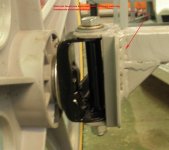
To reduce the brake pedal effort, I cut the vertical shaft above the pivot hole (bottom bolt) angled the top of the cut by 10 degrees, and then welded on an extension that is 2" taller than the old upright. I then attached the foot pad to pieces that I bolted to the upright - this will allow some adjustment as his legs grow.
brake 2.jpg
This is the view down on the brake pedal that shows where the brake cables attach.
front bracing.jpg
In order to work on the body of the car to make it prettier, I reinstalled part of the buck used when creating the body in the front and rear of the car.
front 1.jpg
I am making some progress on smoothing out the body. Fortunately I have a couple of months to go, although I hope to finish the body in the next couple of weeks.
 
OP
J

Jeff Ivers

Well-known member
Joined
Apr 9, 2010
Messages
2,561
Location
Oklahoma
I agree that it is a great sport. Are you working on an "official" soap box racer? Post a pic or two and let use see!

I had a soap box car when I was a kid. Back then, they were all plywood. It was great. Today, I'm working on converting (within the rules) the brakes on a modern downhill racer so that they can be manipulated by hand. I've got some friends who have a daughter that had some bone problems with her legs which make it difficult for her to properly manipulate the brakes. Can't wait!

On a side note, it seems like a lot more people are starting to get back into downhill racing, and that's a good thing. It's a lot of fun.
 

carhunter

Well-known member
Joined
Nov 8, 2010
Messages
793
Location
southern Ohio
Wow, you've got the bug now! Very neat, and I hope your grandson knows how special this is.

I feel silly telling this story, but when I was a kid all I wanted was a go-kart. Dad never had the desire to build or buy one...why, I'll never know. Finally when he was at work one day I sneaked into the garage, took a flat board, a couple rods, some old lawn spreader wheels, and set to building one. I couldn't have been more than 7 or 8?

I painted the board black with a spray can , hammered in nails and bent them over the rods to hold the axles in place, and that was as far as I got before dad caught me.

He was pi$$ed!! Tore the thing apart and never said anything more about it. All the way through junior high I drew plans of go-karts, tree houses, clubhouses...But I never tried to build another ;)

Can't wait to see your next race!
 
OP
J

Jeff Ivers

Well-known member
Joined
Apr 9, 2010
Messages
2,561
Location
Oklahoma
Project Update 8/10/2012

The last several weeks have been spent trying to make the car prettier than last year.

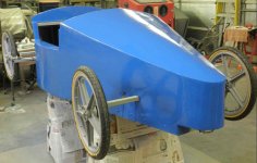
body on chassis 1.jpg
After doing preliminary body work, I decided I needed to remate the body to the chassis to make sure I didn't create any undesired stresses or curves in the body work.
primer 1.jpg
This is a shot showing the car after the second coat of automotive primer.
painted 1.jpg
The car with two coats of Rustoleum spray can paint.
painted 2.jpg
The cockpit.

Next up is to determine assembled weight and make the necessary additional weights to go in the weight box and see about some graphics.
 

Jim Stabe

Well-known member
Joined
Feb 18, 2009
Messages
801
Location
San Diego, Ca
Project Update 8/10/2012

The last several weeks have been spent trying to make the car prettier than last year.

body on chassis 1.jpg
After doing preliminary body work, I decided I needed to remate the body to the chassis to make sure I didn't create any undesired stresses or curves in the body work.
primer 1.jpg
This is a shot showing the car after the second coat of automotive primer.
painted 1.jpg
The car with two coats of Rustoleum spray can paint.
painted 2.jpg
The cockpit.

Next up is to determine assembled weight and make the necessary additional weights to go in the weight box and see about some graphics.

Flat black graphics look good on that color. Look at the Grabber Blue Mustangs.
 
OP
J

Jeff Ivers

Well-known member
Joined
Apr 9, 2010
Messages
2,561
Location
Oklahoma
Carhunter,

My first downhill racer, many years ago, was constructed much as you described. Fortunately it was finished and made several passes down the hill before Dad found out!

Wow, you've got the bug now! Very neat, and I hope your grandson knows how special this is.

I feel silly telling this story, but when I was a kid all I wanted was a go-kart. Dad never had the desire to build or buy one...why, I'll never know. Finally when he was at work one day I sneaked into the garage, took a flat board, a couple rods, some old lawn spreader wheels, and set to building one. I couldn't have been more than 7 or 8?

I painted the board black with a spray can , hammered in nails and bent them over the rods to hold the axles in place, and that was as far as I got before dad caught me.

He was pi$$ed!! Tore the thing apart and never said anything more about it. All the way through junior high I drew plans of go-karts, tree houses, clubhouses...But I never tried to build another ;)

Can't wait to see your next race!
 

GMBracing

Well-known member
Joined
Jun 10, 2012
Messages
54
if you want to weight it. 4 bathroom scales and put one under each wheel. add them up for the total. put the weighrt in the front or the best place to balance the car . more in the front ill cause it to accelerate down the ramp .
 
OP
J

Jeff Ivers

Well-known member
Joined
Apr 9, 2010
Messages
2,561
Location
Oklahoma
Project Update 8/19/2012:

trailer 2.jpg

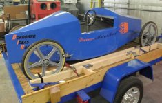
Well, tomorrow I am off to see about graphics for the car. As you can see, I have it loaded on the trailer. I did not want to boom the car down via the body or axles and I did not want to drill holes in my trailer floors and sides, so I constructed a frame that I boomed into the trailer and then boomed the car wheels to this frame.
 
OP
J

Jeff Ivers

Well-known member
Joined
Apr 9, 2010
Messages
2,561
Location
Oklahoma
Project Update 9/1/2012

Well, as of today the cosmetics are as good as they will be for this year. The graphics were installed today.

graphics 1.jpg

graphics 2.jpg

The "blob" with the flames off it is the background for the car number which will be stuck on later.

The finished car weighs 152 pounds, 25 under the maximum weight for the non-competition class. I am working on weights to stack in the weight box to get the car up to racing weight. Have 3 weeks left before the race.
 
OP
J

Jeff Ivers

Well-known member
Joined
Apr 9, 2010
Messages
2,561
Location
Oklahoma
Project update 9/11/2012

Weights.jpg
I have finished preparing weights to get the car up to the Novelty class limit of 177 pounds and the competive class limit of 200 pounds.
Weights installed.jpg
Here the weights are installed in the weight box I added to the rear of the car. I have made a retainer to keep the weights in the box should the car end up upside down, which I believe is highly unlikely - but better safe than sorry, right? The paint on the retainer is currently drying.
Competitive weight - 197.jpg
I am slightly under each of the weight limits, just in case their scales weigh heavy.
 
OP
J

Jeff Ivers

Well-known member
Joined
Apr 9, 2010
Messages
2,561
Location
Oklahoma
Post Race Update -9/24/2012

race 6 - crop.jpg

Here is a shot of my grandson in action (blue car). He made it to the runoffs and ended up in 4th place this year. We had no issues (mechanical failures) with the car during the nine runs he made down the hill. His max speed was 29.9 mph.

When coming off the starting ramp, sometimes the steering wheel would move a bit on him and he had a tendency to overcorrect, which negatively affected his run time. I am considering whether there is something I can do to help this situation for the future.
 
Last edited:

MoonRise

Well-known member
Joined
Nov 5, 2010
Messages
4,030
Location
NJ
Hey, congratulations to you and your grandson.

Sounds like you both had fun.

And ~30 mph in something like that, close to the ground, is pretty darn fast!

re: steering Tighten up the steering links so things don't 'bounce' as much and change the steering 'leverage' so that there is less 'leverage' (smaller diameter steering wheel, shorten steering link arms , etc. Makes steering effort harder but slows down the steering response and makes it take more effort to turn the steering wheel and get a steering change.)
 
To avoid these ads, REGISTER NOW!
Top Bottom