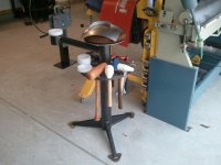
Made a mobile base for my brother's bandsaw at his his cabinet shop.
It's for a 23" Pehaka Vertical saw. The base of the saw has access doors front and rear but they sit flush to the bottom plate of the saw....which means that the saw can't sit down inside the base, it has to sit on top.
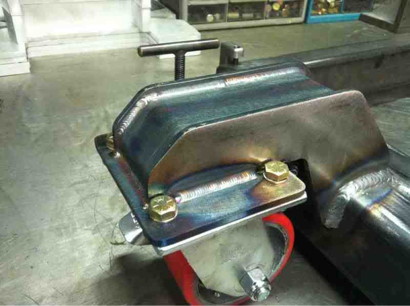
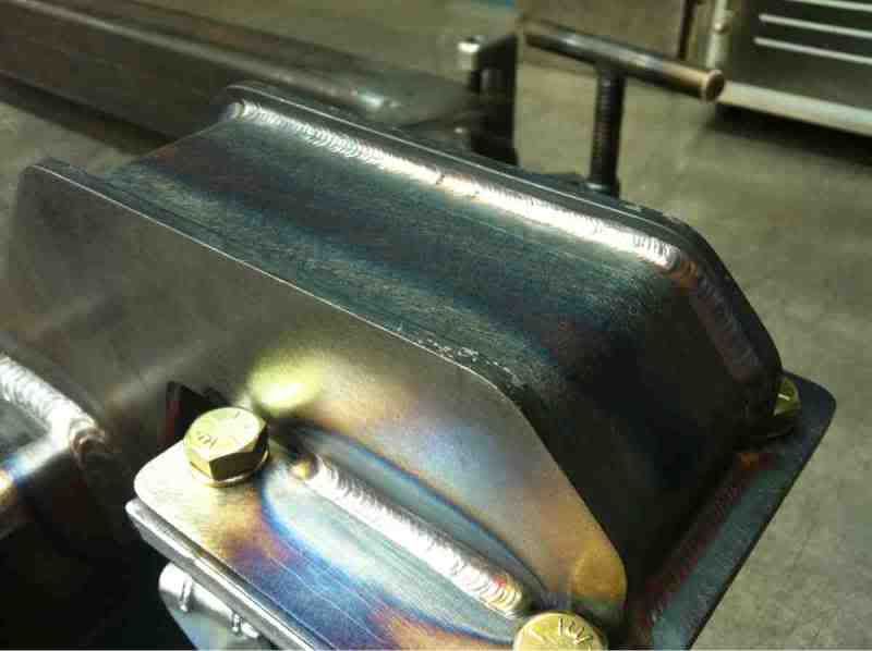
I machined 4 hold downs out of Cold Rolled Steel that use shoulder screws that thread into the base. Then I used angle-tipped set screws on the top that will screw down against the base of the saw. there are also angle-tipped set screws on the bottom that tighten up against the shoulder screw to keep everything snug. (The 1/2" plate in the pics is there to show how the clamps work)
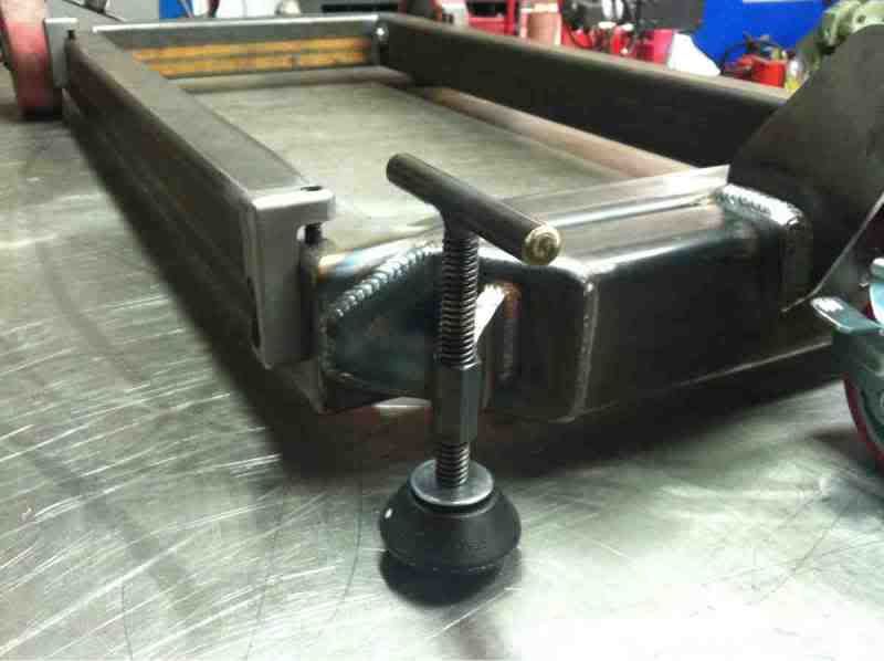
The base is made from 2"x3"x.188" tubing and I made the front caster mount out of 3/16" cold rolled.
I made the level adjuster from 1/2" cold rolled rod, 1/2" acme rod, and the pads are held on with shoulder screws as well so they rotate independently from the acme rod.
The rear wheels are 6" and the front caster is 4".


 If you have the mindset that everything you build is going into an aircraft, it is much more likely that the part will be built properly.


")