paranoid56
Well-known member
made a spinning top out of stainless and a ceramic ball bearing a the tip. first time working with stainless. hoping the next one turns out better. but overall super happy with it.


Nice work, stainless definitely has a learning curve.made a spinning top out of stainless and a ceramic ball bearing a the tip. first time working with stainless. hoping the next one turns out better. but overall super happy with it.
Paranoid have you ever seen the spinner stuff on Instagram?
Some guys spending A LOT of time on those things!
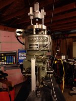
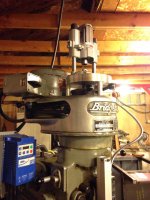
Toshiba horizontal to block up the stock, dah lih vertical for the work here, it will also end up sending some time on a manual millCool, what type of mill are you using ?


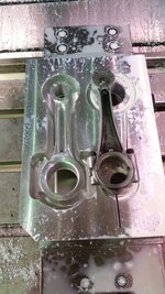
Jim Johnstone;6101606 Partially done a set of connecting rods for an air compressor.[/QUOTE said:Nice work Jim, what type of aluminum did you use?
I had some time on my new HAAS TM-1 CNC that I fit in my basement. Had to lower it 9 inches to fit. I have a couple 2" Wilton Baby vises with no swivel bases and decided to cut a few out of a 3/4 plate. I clamped and bolted down the 3/4 plate to a aluminum Tee style plate that is clamped in my Kurt, this gave me a nice platform to machine these swivel bases.

I used two different angle cutters, a 10 degree on the top cut above the ears and a 7 degree on the bottom, kind of looks like a radius on the side llike the original bases.

Made a fixture to cut the bottom.

The inner ring was easier to cut.


Even though it is not original it came out pretty close to original but once painted it will look pretty close. The steel will not break like the cast base if dropped. That is what I did on one of my Baby base's, I dropped it and it broke.

Nice work Jim, what type of aluminum did you use?
I currently use solidworks for cad and mastercam for cam, but am thinking of looking into solidcam to replace mastercam.Jim and Kevin, what CAM package are you guys using?
Jim and Kevin, what CAM package are you guys using?
Have you had a look at autodesk fusion 360?I use Mechanical Desktop for my cad and Mastercam for cutting. Leftover software from the early 2000's when I built molds. Gotta use old XP software to run this software.
Have you had a look at autodesk fusion 360?
Thanks, my fabricator is waiting for a sample of some brazing rod from his supplier to test it out.I'll be honest, I can cut anything I want including cores and cavities for molds. I was software broke back when I was building Molds. I used Hypermill nested in Mechanical Desktop but have since moved back to Mastercam 9 which cuts anything I build now. I am going to explore Fusion 360 because I am curious. Thanks Jim.
I am curious on brazing bronze to aluminum and will be checking in now and then. Good luck on your rod building.
A few things i have made over the years. I own a small machine shop, with for the most part state of the art cnc machines. 3-4 axis machining and turning centers. Also have small to medium manual lathe/milling machines.
I'll be honest, I can cut anything I want including cores and cavities for molds. I was software broke back when I was building Molds. I used Hypermill nested in Mechanical Desktop but have since moved back to Mastercam 9 which cuts anything I build now. I am going to explore Fusion 360 because I am curious. Thanks Jim.
I am curious on brazing bronze to aluminum and will be checking in now and then. Good luck on your rod building.
 But I only have a 2 axis P-trak.
Prototyped an on head spring compressor for LS cylinder heads. Working on my junky round column mill drill, best machine I could afford. First project I've pushed through it to date. With the process more or less figured out I'll be producing a few of these and some other parts for local guys. Goal is to do enough work to pay for better machines!
Also played around with some "walking the cup" on the weld. So if it looks ridiculous that's why haha. Not the application for it but for a prototype I figured why not.
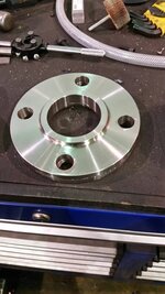
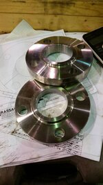
Neat little job today. Customer dropped off 2 stainless flanges and asked us to make a split flange from them.

Well the first thing I did was sit at the computer and draw the flange in solidworks and sort out exactly how I was going to split them to fit each other.Nice job on the flange. How about describing how you did that?


Neat little job today. Customer dropped off 2 stainless flanges and asked us to make a split flange from them.


It looks like the diameter of the inside hole is larger than the clearance of each flange half.
I'm wishing I had an opportunity to speak directly with the customer, boss just brought me the flanges and told me what they wanted. I did point out to the boss that the rad closed up past the 180 degree point, he replied "make it to the print". They never brought it back to rework so I guess it must have done whatever they wanted of it.I'm super curious as to why the customer wanted a split flange. You can't install that onto a tube or pipe in halves so what other purpose would the split have?
I'm wishing I had an opportunity to speak directly with the customer, boss just brought me the flanges and told me what they wanted. I did point out to the boss that the rad closed up past the 180 degree point, he replied "make it to the print". They never brought it back to rework so I guess it must have done whatever they wanted of it.
I'm wishing I had an opportunity to speak directly with the customer, boss just brought me the flanges and told me what they wanted. I did point out to the boss that the rad closed up past the 180 degree point, he replied "make it to the print". They never brought it back to rework so I guess it must have done whatever they wanted of it.
Machined this brand for a friend of mine today. He's going to use it to burn some wood pieces for his wedding. I'm going to cut out a handle for it and weld it on the back.


![20160818_125008[1].jpg](/forum/data/attachments/516/516125-ca010e6ba8c34de4699ffe591ccbb7b4.jpg)
![FB_IMG_1459547656149[1].jpg](/forum/data/attachments/515/515948-fd113d9f61fc449d441321136a6eb6a3.jpg)
![FB_IMG_1459547662321[1].jpg](/forum/data/attachments/515/515980-187d0320f4566e8d6d57a8931d815f57.jpg)
![20150625_125904[1].jpg](/forum/data/attachments/516/516018-cb0a3af17f324b97e690f7d0fc9d7e98.jpg)
![20160812_002423[1].jpg](/forum/data/attachments/516/516088-a4580be99fe1538d6dba5148f2c57a48.jpg)