To avoid these ads, REGISTER NOW!

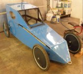
Latest fab. project - downhill racer

bigsteve2011

Well-known member
Joined
Jun 13, 2014
Messages
73
Location
Metro Detroit
I always love seeing stuff like this that kids involved in engineering/building of things.

My senior design project in college was designing a 3 wheeled electric race car for NECA racing (http://www.necaracing.com/) similar to Electrathon America (http://www.electrathonamerica.org/Welcome_to_Electrathon_America.html)

The NECA racing is a bunch of local Michigan high schools/tech schools who race the electric cars against one another on either oval tracks or a road course set up in a parking lot. The high school teacher wanted a extremely safe car for the kids to race. We did a finite element analysis and other modeling to determine the safety requirements of the car etc since the cars ran at around 45mph. Also designed the suspension and steering to reduce amount of wasted energy.

I'd bet you could find some good ideas from looking at pictures of the electrathon america cars.

I would bet the most improvement in the car would come from trying to reduce your rolling resistance of the car, by doing things like Ackermann steering and having minimum scrub radius (sorry if you have already set up car for this)

Keep up the good work!
 
To avoid these ads, REGISTER NOW!
OP
J

Jeff Ivers

Well-known member
Joined
Apr 9, 2010
Messages
2,561
Location
Oklahoma
As I mentioned in a previous post, I have begun acquiring components for a second downhill racer. I posted pics of the steering wheel and brake lever.
I have now acquired:
disk brakes.jpg
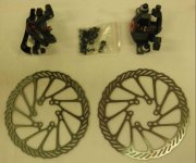
disk brakes,
Hub and rim.jpg
hubs and rims,
P2210002.JPG
and a steering rack.

Had to pay more than I wanted for the steering rack - $90. It has taken a long time to find hubs and rims as my requirements are 20" wheels and replaceable sealed bearings to allow me to change to synthetic bearings. Sellers of hubs barely tell you if the bearings are sealed and do not provide dimensions of the bearings. I am currently waiting on spokes, so I can lace these wheels together. I am still waiting to hear about replacement end caps for the hubs that I can drill out to fit a .5 inch axle. I think that will be cheaper than trying to buy 15mm rod for my rear axle.

Basically, I need to finalize the rear axle diameter and assemble the rear wheels with disk brakes in order to be in a position to start designing the chassis.
 
OP
J

Jeff Ivers

Well-known member
Joined
Apr 9, 2010
Messages
2,561
Location
Oklahoma
Today, I finished prepping all 4 wheels for the 2nd downhill racer. The first 2 wheels are spares from the first car and have semi-synthetic bearings installed in them. On one of the wheels, the bearings felt notchy when I turned them by hand, so I removed the bearings and they felt fine. I decided the center of the wheel where the bearings press in was not as round as it should be, so I got out the dremel and a small diameter sanding wheel and removed a small amount of material and then re-installed the bearings (and then repeated the process a couple of times) until the bearings smoothed out. The second set of wheels are my new 20" disk brake wheels that I had to build from scratch (a separate thread documents the search and acquisition of parts). Here is the finished product:
downhill 2 wheels 2 r.jpg
Next, I will start developing the plans for the frame.
 
OP
J

Jeff Ivers

Well-known member
Joined
Apr 9, 2010
Messages
2,561
Location
Oklahoma
Finally, I am making some traction on the design and build of downhill racer #2!

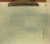
First, I need some kind of plan:
downhill 2 plans r.jpg
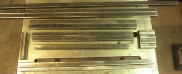
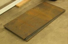
Then some material cut to length:
first batch of frame components r.jpg
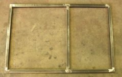
With a little welding and a lot of grinding, the first frame section:
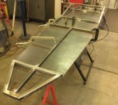
frame 1 r.jpg

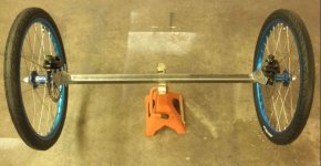
As on downhill number one, I constructed the rear axle from a piece of .75 inch tubing welded into a piece of 1" tubing and a .5 inch rod welded into that assembly. The rod extends about 6" either side of the tubing. I Welded a large washer over each end to have something for the wheel bearing to but up against.
axle end r.jpg
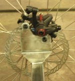
Next, it is time to fab some brake brackets.
brake bracket 1 r.jpg
This shows the first bracket clamped in place with the brake and wheel installed. After I complete the second bracket, I will weld these to the axle.
brake bracket 2 r.jpg
The hubs I bought, came with 12mm inserts. I drilled these out to .5 inch. I then had to hand polish with 220 grit each of the axle ends until the wheels and bearings would slide on. This shows the first wheel spinning away.
Wheels fitted to hand polish axle r.jpg
 
OP
J

Jeff Ivers

Well-known member
Joined
Apr 9, 2010
Messages
2,561
Location
Oklahoma
Now we're going places. Looks fantastic. Keep up the good work.


Thanks for checking in and the words of encouragement!

Today, I finished the rear axle assembly - 9 separate pieces of metal welded together with appropriate shaping. When I was working on the second brake bracket, I realized I did not have the caliper assembly on the 1st bracket positioned correctly, so most of today was spent making the appropriate adjustments. These brakes are very effective - might have to watch out for whiplash!
1st brake bracket r.jpg
2nd brake bracket r.jpg
rear axle assemb r.jpg
 

TheEquineFencer

Well-known member
Joined
Jan 15, 2009
Messages
9,278
Location
Farmville, NC 27828
I have some questions. Where did you get the brake parts and the steering section? I'm going to be building something before long that will need something similar. Are the calipers cable or hyd?
 
OP
J

Jeff Ivers

Well-known member
Joined
Apr 9, 2010
Messages
2,561
Location
Oklahoma
I have some questions. Where did you get the brake parts and the steering section? I'm going to be building something before long that will need something similar. Are the calipers cable or hyd?

The steering rack came from nexgen off-road. The cable activated calipers from afterpartz.
 
OP
J

Jeff Ivers

Well-known member
Joined
Apr 9, 2010
Messages
2,561
Location
Oklahoma
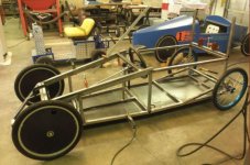
Today, I attached the rear axle to the rear frame section and added some diagonal bracing. This represents 24 separate pieces of metal sahped and welded together.
rear frame 4 r.jpg
 
OP
J

Jeff Ivers

Well-known member
Joined
Apr 9, 2010
Messages
2,561
Location
Oklahoma
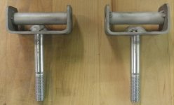
Yesterday, I got the front lower frame completed and assembled with the rear frame, then added the uprights for the front axle. The front axle will be a 1" square tube that will support the front spindles on each end. Before I cut the axle, I need to complete the front spindles so I can calculate the width of the axle so that the front wheels will be in alignment with the rear. The rear track is 34". So today I started on the front spindles.
spindle 1.JPG
spindle 2.JPG
Next, I have to add a steering arm to each of these and then complete the outer spindle brackets that these will be suspended within.
 
OP
J

Jeff Ivers

Well-known member
Joined
Apr 9, 2010
Messages
2,561
Location
Oklahoma
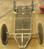
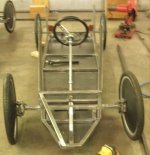
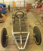
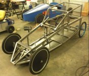
Today, I finished the front spindles and attached them to the frame. 4 Wheels on the ground!
4 wheels down r.jpg
On the spindles, I did not have two sections of C channel (or box channel that could be split) that would just fit inside each other as I did for downhill one. Couldn't see spending the money for a 10 or 20 foot section of a size of metal that I would only use a few inches of. So, I am using washers to take up the slack.
spindle 3 r.jpg
Should work just fine. My daughter and grandsons are coming up this weekend so we can do some calculations on steering wheel placement, brake handle placement and body height.
 
OP
J

Jeff Ivers

Well-known member
Joined
Apr 9, 2010
Messages
2,561
Location
Oklahoma
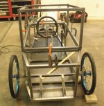
With the race just under 2 months away, my daughter brought my grandsons up this past weekend so we could take measurements to confirm seating, steering placement and overall height.

The last couple of days, I have been working on finishing the steering and the brake actuator placement.

Tomorrow, I start on the superstructure.

Here is where I am at:
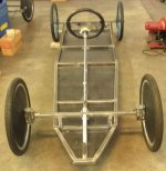
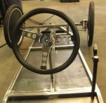
Steering 2 r.jpg
View of completed steering from the front of the car.
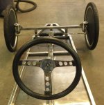
Steering 3 r.jpg
View of the completed steering from the drivers seat.
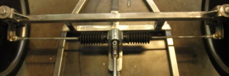
Steering 4 r.jpg
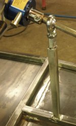
The steering rack/tie rod assembly.
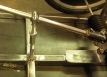
Steering 5 r.jpg
Front steering shaft support.
Steering 6 r.jpg
Rear steering shaft support.
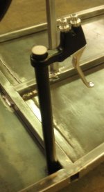
Brake 1 r.jpg
Brake actuator support. This may have to be moved inboard a bit when I add a body.
Brake 2 r.jpg
Side view of brake actuator.

Interestingly, both downhill 1 and downhill 2 ended up with 71 inch wheelbases. The track on DH1 is 41 inches, but the track on DH2 is 34 inches.
 
OP
J

Jeff Ivers

Well-known member
Joined
Apr 9, 2010
Messages
2,561
Location
Oklahoma
My goals for this project have always included an enclosed body with opening panels so I can get my old body into it, reduced frontal area compared to DH1, and as streamlined as I can make it.

I had sketched out some basic plans to establish the floor plan and possible side view, so I commenced building the superstructure.
superstructure  1 r.jpg
After looking at it, I decided I could make it more streamlined and make it easier to create opening panels, so I clamped some 4-ft sticks on to mark where to cut off what I had welded on.

superstructure 2 r.jpg
This shows the direction I am heading.
 
OP
J

Jeff Ivers

Well-known member
Joined
Apr 9, 2010
Messages
2,561
Location
Oklahoma
Over the last few days, I have made some progress on the superstructure. I made the frame for the opening panel that will cover the drivers legs and steering shaft. I also started framing the opening top. The front panel will open to the side and the top will open to the rear. The yardstick is clamped to show the approximate angle of the front of the top and where it will intersect the front body. Please excuse all the background noise in the pictures.
Superstructure 6 r.jpg
Superstructure 7 r.jpg
Superstructure 8 r.jpg
 
OP
J

Jeff Ivers

Well-known member
Joined
Apr 9, 2010
Messages
2,561
Location
Oklahoma
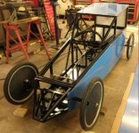
Today, I finished cutting tubing and welding up the frame (unless I decide to add some additional bracing). I have used about 120' of 1" tubing and about 5' of 3/4" tubing. 100 separate pieces welded together. This afternoon, I unclamped the three assemblies and started the process of flipping each assembly to weld those joints I could not get to before and making sure all welds are cleaned up and ready for powder coating. I hope to take the assemblies in to the PC on Monday and go pick up the aluminum for the body.
Superstructure 14 r.jpg
This picture shows how I laid out the windshield frame that will rest on the top of the opening panel that covers the leg area.
Superstructure 16 r.jpg
The rear of the car.
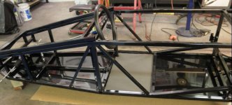
Superstructure 17 r.jpg
This give a good overall view of the shape. Does it look kinda like a duece coupe?
Superstructure 18 r.jpg
Front view.
 
OP
J

Jeff Ivers

Well-known member
Joined
Apr 9, 2010
Messages
2,561
Location
Oklahoma
On July 31, I hauled the DH2 chassis off to the powder coaters. While I was waiting on them to complete, (est. 1 week), I decided to acquire the materials to create the body and to add ballast up to the max of 200 pounds.
DH2 ballast material 2.JPG
Ballast material
DH2 body material r.jpg
Body material

I also decided to see if I could create an enclosed top for DH1.
DH1 top 1 r.jpg
This shows my first steps.

On August 6, a tornado hit Tulsa. I lucked out - it missed the powder coaters by 150 feet. Had a couple of days of imagining my chassis wrapped around a tree somewhere.
 
OP
J

Jeff Ivers

Well-known member
Joined
Apr 9, 2010
Messages
2,561
Location
Oklahoma
Yesterday, I piked up the chassis components from the powder coaters.
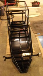
Superstructure 19 r.jpg
There is nothing like a little powder coating to start making a project look good.
Superstructure 20 r.jpg
Before, I took the chassis in, the final step was to add some diagonal bracing.

Once I got everything back, I commenced final assembly.
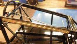
Final assembly hood hinge r.jpg
The "hood" hinge added.
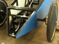
Final assembly 1st body panel r.jpg
The first body panel installed.
Final assembly top hinge r.jpg
The top hinge added.

I went to the local bike shop to get a 6' and a 9' brake cable - $79 Wow!.
Still waiting on the core for the 9'.
 
OP
J

Jeff Ivers

Well-known member
Joined
Apr 9, 2010
Messages
2,561
Location
Oklahoma
I continue to make progress on the body of Downhill 2.
Foot stop r.jpg
Added a foot stop to prevent sliding into the steering rack.
Final assembly 2nd body panel r.jpg
Final assembly 2nd body panel 2 r.jpg
Second body panel installed.
Final assembly installing body panel 3 r.jpg
This shows the third body panel being installed. Note the open panels. I have removed the tie rod until the panel is installed.
Final assembly body panel 3 r.jpg
Final assembly body panel 3 2 r.jpg
Third body panel installed.
 
To avoid these ads, REGISTER NOW!
OP
J

Jeff Ivers

Well-known member
Joined
Apr 9, 2010
Messages
2,561
Location
Oklahoma
Well, after a couple of days off for an out-of-state funeral, I got back on the car today.
Final assembly body panel 4 r.jpg
Fourth body panel.
Final assembly body panel 5 r.jpg
Fifth body panel.
Final assembly body panel 6 r.jpg
Sixth body panel.
Final assembly body panel 7 r.jpg
Seventh body panel.
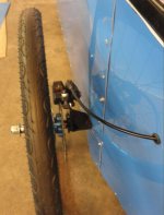
Final assembly left brake r.jpg
Left brake operational.
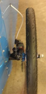
Final assembly right brake r.jpg
Right brake operational.
 
OP
J

Jeff Ivers

Well-known member
Joined
Apr 9, 2010
Messages
2,561
Location
Oklahoma
Yesterday, I got the brakes operational. I had guestimated that I needed a 6' and a 9' bake cable. The local bike shop fixed me up with the short cable and outer sheaths for both, but had to order the long cable. It was due in 3 days ago but had not arrived.

Since I am trying to get the car driveable for the grandsons to come up this weekend for trial runs, I decided to at least get the short cable installed. When I got it attached to the brake handle and routed to the rear wheel, I decided I had far more length than I needed. So I marked the cable where it could be cut and then measured the excess. I then hit my bike scrap bin and found a salvaged cable the exact length I needed, so it went in on the right wheel side. I then figured out the 6' was long enough to work for the left wheel, so I installed it. Today the ordered cable arrived!

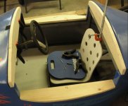
Continuing on the theme of having the car operation, I suspended work on the body panels and focused today on getting the seat back with adjustment installed, prepping the first ballast plate and making a provision for mounting the ballast plates.

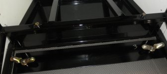
Final assembly seat brace ballast attach r.jpg
This shows the seat brace assembly. The wing nuts will hold the ballast plates in place.
Final assembly seat forward pos r.jpg
The seat in the forward (upright position for my grandson).
Final assembly seat rear pos r.jpg
The seat in the rear position - for grandad.
 
OP
J

Jeff Ivers

Well-known member
Joined
Apr 9, 2010
Messages
2,561
Location
Oklahoma
Installed body panels 8 and 9 and the tow hook.
Final assembly body panel 9 2 r.jpg
My daughter brought my grandsons up yesterday and we hauled both downhill racers over to a local church where we could take some practice runs down the hill. Now I just have to complete everything before the September 16 race in Sand Springs, OK!
 
OP
J

Jeff Ivers

Well-known member
Joined
Apr 9, 2010
Messages
2,561
Location
Oklahoma
Weekend before last, my daughter brought my grandsons up for some trial runs.

Since then I have:

Final assembly brake stalk support r.jpg
Added a support bracket for the brake stalk.
Final assembly body panel 10 1 r.jpg
Installed body panel 10 with plexiglass "window" insert.
Final assembly body panel 11 r.jpg
Installed body panel 11.
Final assembly top catch r.jpg
Installed a top catch.

Today, I bought polycarbonate for the windshield.

I am somewhat bummed because after the trial runs, I discovered the rear axle on the new car where it extends from the chassis has bent slightly on both sides. I thought .5 inch rod was more than adequate for the loads. I don't know if I got some cheap steel, didn't know enough metallurgy to ask for the proper grade of steel, or what. I have had no issues with the first downhill racer which has an even wider axle made the same way. However, I did put my 215 pounds into the new car for a trial run or two. Not sure what to do about the situation. Any thoughts?
 
OP
J

Jeff Ivers

Well-known member
Joined
Apr 9, 2010
Messages
2,561
Location
Oklahoma
Today, I:
Final assembly body panel 12 r.jpg
Installed the 12th body panel.
Final assembly body panel 13 r.jpg
Installed the 13th body panel.
Final assembly windshield r.jpg
Installed the windshield.
Final assembly 2nd top latch r.jpg
Installed the second top catch.

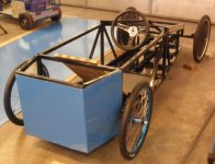
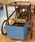
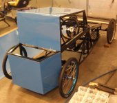
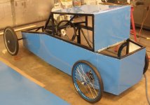
Final assembly complete r.jpg
Resulting in an almost compete racer. I still have a speedometer to install, some trim and caulk work, graphics, and of course the rear axle issue.

On the side windows, I used 1/8 plexiglass that I glued in with clear silicon. I believe there will be very little pressure on them. However, since the car will be towed at highway speeds, I felt the windshield would not survive if I used that material. I went to the local plastics shop and they recommended polycarbonate - I went with 3/16.
 
OP
J

Jeff Ivers

Well-known member
Joined
Apr 9, 2010
Messages
2,561
Location
Oklahoma
Since I am essentially done with DH2, except for a few minor details (installation of speedometer), I decided I would shift my efforts to trying to create a top for the original racer (DH1) to try to streamline it better.

I spent the last couple of days working on it. My idea was to make a lift-off insert for the driver compartment.

DH1 top 3 r.jpg

This shows the creation of forward and aft cross pieces and bases for the bottoms of the "step" on each side.

DH1 top5 r.jpg

This shows the forward and aft crosspieces tied together with a shaped piece to form the top of the "step" insert. It also shows some yardsticks clamped in place to try to check dimensions and calculate angle of roof slope.

It was at this point that I sat down and thought about the next steps and realized some problems:

1) I was making this as an insert because of all the weird angles and lack of attachment points for a hinged top as on DH1. To continue in this way, I will end up with a 30" tall insert, the bottom of which must be lifted 4' off the ground to clear the driver's head. If we have a typical OK windy day, this may be a problem.

2) I have only parts of 7 days left that I can work on this before the Sep. 16 race.

3) I can't figure out how to adequately brace the windshield if it extends out over the front of the car. If I limit the bottom of the windshield to attaching to the insert, then it will be like a wall going down the hill which may be more of an aerodynamic hindrance.

So, I think I am going to table this idea for this year. I'll call it a change in direction rather than a failure!
 
OP
J

Jeff Ivers

Well-known member
Joined
Apr 9, 2010
Messages
2,561
Location
Oklahoma
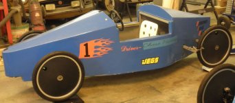
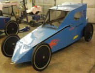
DH1 - all dressed up r.jpg
DH2 - all dressed up r.jpg

Well here we are, all dressed up and NO PLACE TO RACE! Last Saturday, I received word that the race scheduled for this coming Saturday, Sept. 16th has been postponed till 3/31/2018!

I decided to slow down on the punch list of items to complete before the race. I have discovered washer diameter on the wheels is a major issue and am working to optimize drag on all wheels. This will also give me time to address the rear axle issue on DH2.
 
OP
J

Jeff Ivers

Well-known member
Joined
Apr 9, 2010
Messages
2,561
Location
Oklahoma
Since the race was postponed till March, I have been working on improving performance and correcting the rear axle problem.

I discovered that just because you have installed semi-synthetic bearings, there is still more work to insure you are receiving the benefits. After messing with out-of-round hubs that were stressing the bearings, resulting in a notchy feeling and playing with washers to insure the wheels are located with low drag, I can now jerk a wheel once and watch it coast for 5 minutes before coming to a stop.

Bent axle evidence r.jpg

If you look at the bottom of the axle, you can see the evidence of the bend.

Bent axle r.jpg

Bent axle removed.

Drilled axle R r.jpg

This is what I had to do to remove the axle.

Next up is finding a more appropriate material for the axle and installing the new axle.
 
OP
J

Jeff Ivers

Well-known member
Joined
Apr 9, 2010
Messages
2,561
Location
Oklahoma
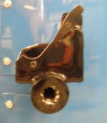
As you can see in the above post, I extracted the bent axle by drilling through the washer around the inner circumference to break the welding bond on the rear of the washer. This allowed me to tap out the old axle. I ordered a length of 4140 heat treat steel for the new axle. It is rated about twice a s strong as what I think I had in there - I don't have a way to test the axle I removed.

On the chance that welding the old axle weakened it, I decided the new axle should be located with some clamps. I drilled some holes through the square tubing, welded on a couple of nuts and inserted some bolts to tighten against the axle. The axle can't come out anyway, but this will prevent rotation.
Axle clamps r.jpg
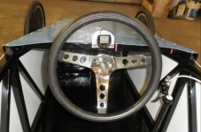
I discovered the quick release button for the steering wheel was hitting the speedometer (bike computer), so I added a panel to relocate it to.
DH2 drivers controls r.jpg
All buttoned up and ready to race.
DH2 new axle 10102017 1 r.jpg

I have spent a lot of time reducing drag on the wheels. I have one wheel that is not performing as well as the other 3, but haven't come up with any ideas to improve the situation unless I order another set of bearings. Considering the cost, I am not sure the potential gain is worth it. I do want to recheck the front wheel alignment, but I have lots of time to get that done before March 31.

Total weight on the car is exactly 200 pounds (the limit, according to the rules). That includes a single 3 pound ballast plate.
 
OP
J

Jeff Ivers

Well-known member
Joined
Apr 9, 2010
Messages
2,561
Location
Oklahoma
I think I am overdue in bringing this post up-to-date, so I will make several posts over the next few days to let everyone know where I am at.

Two weeks before the re-scheduled March 31, 2018 Sand Springs Downhill Derby, we received notice the race had been cancelled with no mention of any rescheduling or future races. In addition, they have still not refunded the entry fee paid by my daughter for the race. Bummer!

I was setting on two prepped downhill racers, one of which had not seen any track time, so I started looking for alternate race venues. I found a number of adult only races and a couple that allowed youth entries. The nearest race (time wise) was April 14 in Macon, GA, called the Magnolia Derby. Due to the distance, it was not possible to take the grandsons to this race (school), so I decided to enter myself and haul Downhill 2 to GA.

The event was well run and well attended.

Magnolia 2018 Derby 1 r.jpg
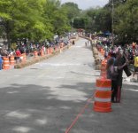
This picture is looking downhill from just behind the start line. The tall signs on either side of the track past the individuals standing on the track are the finish line. The finish line is around the corner to the left. The end hay bales are about as far from the finish line as the person standing in the track closest to the top of the hill is. In other words, the braking area is very short compared to what I have experienced at Sand Springs.

I had ballasted the car up to 229 pounds and with my helmet and clothes on, I added about another 240 pounds.

When it was my turn to run, I climbed in the car and headed downhill. I immediately sensed that the back axle may have bent again. When I got to the finish line and started braking, my suspicions were confirmed as my braking action was not as expected. I ran into the hay bales, resulting in a slight bend in one of the front spindles, throwing off the alignment. I was out after one run. I also discovered that my bike computer was not working, so don't know how fast I was going, but it felt like I hit about 40.
 

TheEquineFencer

Well-known member
Joined
Jan 15, 2009
Messages
9,278
Location
Farmville, NC 27828
I think I am overdue in bringing this post up-to-date, so I will make several posts over the next few days to let everyone know where I am at.

Two weeks before the re-scheduled March 31, 2018 Sand Springs Downhill Derby, we received notice the race had been cancelled with no mention of any rescheduling or future races. In addition, they have still not refunded the entry fee paid by my daughter for the race. Bummer!

I was setting on two prepped downhill racers, one of which had not seen any track time, so I started looking for alternate race venues. I found a number of adult only races and a couple that allowed youth entries. The nearest race (time wise) was April 14 in Macon, GA, called the Magnolia Derby. Due to the distance, it was not possible to take the grandsons to this race (school), so I decided to enter myself and haul Downhill 2 to GA.

The event was well run and well attended.

Magnolia 2018 Derby 1 r.jpg
This picture is looking downhill from just behind the start line. The tall signs on either side of the track past the individuals standing on the track are the finish line. The finish line is around the corner to the left. The end hay bales are about as far from the finish line as the person standing in the track closest to the top of the hill is. In other words, the braking area is very short compared to what I have experienced at Sand Springs.

I had ballasted the car up to 229 pounds and with my helmet and clothes on, I added about another 240 pounds.

When it was my turn to run, I climbed in the car and headed downhill. I immediately sensed that the back axle may have bent again. When I got to the finish line and started braking, my suspicions were confirmed as my braking action was not as expected. I ran into the hay bales, resulting in a slight bend in one of the front spindles, throwing off the alignment. I was out after one run. I also discovered that my bike computer was not working, so don't know how fast I was going, but it felt like I hit about 40.

LOL, now you know how the FC/TF guys feel when things go wrong at the top end....but on a smaller scale...
 
OP
J

Jeff Ivers

Well-known member
Joined
Apr 9, 2010
Messages
2,561
Location
Oklahoma
LOL, now you know how the FC/TF guys feel when things go wrong at the top end....but on a smaller scale...

Yeah, it was kinda funny. I've decided to keep my large posterior out of the racer and leave the downhill racing to my grand kids!

I wish I knew more about metallurgy. I used regular hardware store .5 inch bolts (grade 5?) inserted in a hole in a C-shaped piece of steel to form the front spindles for both cars and have had no problems with them bending. On DH1, for the rear axle, I inserted a .5 inch steel rod through a .75 inch steel tube and that assembly through the 1 inch steel tube that was part of the frame. The .5 inch rod extends about 5 inches beyond the tubing on both sides and the wheels are slid on and held in place by a nut threaded onto the end of the rod, which was threaded. This has worked fine on that car (which I have not attempted to drive).

On DH2, I used the same technique for the rear axle and after my grandson ran it into a ditch on a test run and I attempted a test run, I discovered the rear axle had bent significantly. On this car, the .5 inch rod extends about 6 inches from the tubing on each side due to the space required by the disk brake hub. This also means the weight load is focused about 1 to 1.5 inches further outboard of the ends of the tubing. After the first axle bent, a machinist friend suggested that I needed to use the heat treat metal referenced in an earlier thread. Since this was supposed to be much stronger, I thought my problem was solved.

After my experience in Macon, I examined the axle and determined it had bent just slightly inside the tubing because the rod was clamped to the bottom of the tubing in the center which left a fraction of an inch of free space above the rod inside the tube on each end. I weighted the car down with the equivalent weight of my grandson, verified the axle had not bent any further, realigned the rear brakes and away we went.

Everything worked fine for him on race day, but I would still like to solve the problem and get my wheels back to perpendicular.

Can anyone out there help me with this? Is there a different steel I should use? Is there some other step to take to keep the axle rigid when the total car weight approaches 500 pounds?
 
OP
J

Jeff Ivers

Well-known member
Joined
Apr 9, 2010
Messages
2,561
Location
Oklahoma
I named our race team "Borrowed Ideas Racing". I am not a machinist nor a mechanical engineer. I have a lifetime of experience at taking things apart and fixing them and building things from scratch. Much of what I have learned is from what did not work previously. Before starting construction of the first racer, I attended a race and wandered through the pit area looking at how others had built cars and taking pictures of things that looked promising and things that didn't work for others.

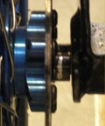
Standard bike wheels use axles that are less than .5 inch in diameter. Those axles are supported on both sides.

PA150091 r.jpg
This is one car constructors technique for attaching bike axles to a car frame.
PA150092 r.jpg
This is the result.

We just got back from attending a downhill race in Muscatine, IA on July4 (more later). At that race, I saw a car that had used the same technique as above. The picture below shows the result.
Muscatine 22 r.jpg
 

bdbecker

ALLIANCE MEMBER
Joined
Nov 18, 2015
Messages
5,574
Location
Iowa
...After the first axle bent, a machinist friend suggested that I needed to use the heat treat metal referenced in an earlier thread. Since this was supposed to be much stronger, I thought my problem was solved.

After my experience in Macon, I examined the axle and determined it had bent just slightly inside the tubing because the rod was clamped to the bottom of the tubing in the center which left a fraction of an inch of free space above the rod inside the tube on each end...

Did your bend occur near where you welded the axle to the tube? What alloy did you use for the axle? (tried looking back through the tread and couldn't find this info). Depending on the alloy, and your weld process, you may have actually softened the axle in the area affected by the heat of your weld.
 

MoonRise

Well-known member
Joined
Nov 5, 2010
Messages
4,030
Location
NJ
500 lbs, plus bumps, on an axle with the wheel mounted 6"+ outboard in a cantilever arrangement, is a bit tough on a 1/2" diameter axle.

As you have found out.

https://mechanicalc.com/reference/beam-analysis-1

Some quick numbers.

500 lbs, spread over 4 wheels, is 125 lbs at each wheel.

Add in some bump in the road and allowing for some non-uniform weight distribution, and let's run some numbers with 250 lbs at a wheel.

A 1/2" diameter shaft has a moment of inertia

https://mechanicalc.com/reference/cross-sections#moment-of-inertia

of I = pi * d^4/64

= 3.14 * (0.5)^4 / 64 = 0.003 in^4

Maximum bending stress = (bending moment) * (centroid distance) / (I)

The bending moment (aka torque) is the force * the lever arm distance, so in this case you have

250 lb * 6 inch = 1500 in-lb

The centroid distance is just the distance from the 'middle' of the beam (in this case the axle) to the outer 'skin'. Your circular axle is symmetrical, so the distance from the 'middle' to the 'skin' is just the axle diameter / 2 . Or just the axle radius.

0.5" / 2 = 0.25"

So the maximum bending stress for your 1/2" diameter shaft with 250 lbs force applied to a 6 inch cantilever length is

(1500 in-lb ) * (0.25") / (0.003 in^4) = 125,000 psi max bending stress

Which is more stress than plain steel or hardened 4140 steel can handle before actually deforming and bending. Which is why your axles bent.

You could try and get some 'stronger' 1/2" steel bars, but that is more $$$$.

You can shorten the cantilever length that the axle sticks out.

You can lower the forces.

Or you can just use a bigger diameter axle. Even if you have just the very end of the axle turned down to the 1/2" diameter to fit into your wheel bearings.

If you use a 1" diameter shaft and everything else stays the same, your bending stress changes from 125,000 psi to 15,000 psi.

(1500 in-lb) * (0.5 in) / (0.049 in^4) = 15,300 psi max bending stress

Which means plain mild steel can handle that and not permanently bend.

:beer:
 
OP
J

Jeff Ivers

Well-known member
Joined
Apr 9, 2010
Messages
2,561
Location
Oklahoma
Did your bend occur near where you welded the axle to the tube? What alloy did you use for the axle? (tried looking back through the tread and couldn't find this info). Depending on the alloy, and your weld process, you may have actually softened the axle in the area affected by the heat of your weld.

On the replacement, I used 4140 heat treat and did not weld it at all. On the inside of the car, about 6" from each side, I installed a clamp bolt through a nut welded to the square tubing to hold the .5 inch rod on the bottom of the tubing.
 
To avoid these ads, REGISTER NOW!
Top Bottom