
How about some bench building? I think work benches are the heart of any shop. You spend a lot of time at them so why not make that a pleasant environment and something aesthetically pleasing to the eye? As you've seen the old benches were in terrible condition what little you could see of them. Really not even worth salvaging. I cleaned up the cast iron welders bench and used it but I needed some good general work benches elsewhere in the shop. Here's how I went about building those. They say 1 picture is worth a 1000 words so I've got a bunch of pictures here showing the construction.
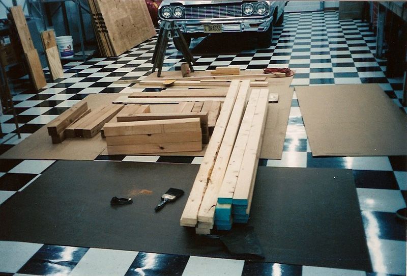
This is the pile of material I started with. Those are the sheets of 1/4" Masonite as well as card board I used to protect the tile floor.
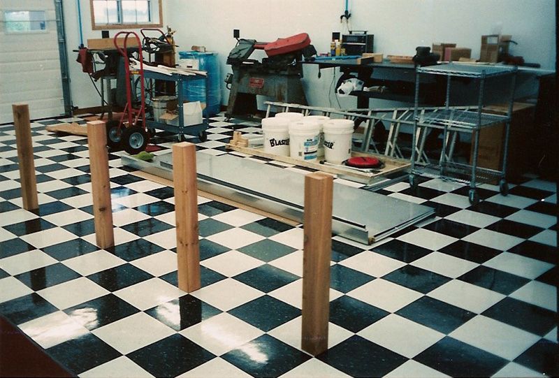
Fabricating in the fabrication room!! I build three benches, 2 - 10' long and 1 - 8' long. The 10 footers had 4 legs across as seen here and the 8 footer had 3. Legs were 4" X 4". The floor tiles are 1 foot square so that helped with the general lay out. Piled in the background are the bench tops. I had a local machine shop bend them up for me. I had the front edge bent all the way under the front lip so if you clamp something along the front edge the bottom of the clamp would be bearing on metal and not on the bottom edge of the wood substrate. I also had a 4" back splash with a top edge on it to prevent objects from rolling off the back. I used 12 gauge stainless steel which is pretty thick metal. That should resist denting over the years and of course they can't rust. Also see that the ends are unfinished so I had end caps in the profile of the tops made which were tig welded to the edges to finish it off. I didn't want the wood substrate seen from an end view. They could bend 10' long, 12 gauge stainless and give me a 1/2 lip on top of the back splash. Pretty nice piece of work. They needed to use a hydraulic brake to bend them.
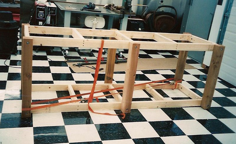
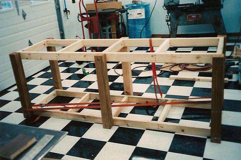
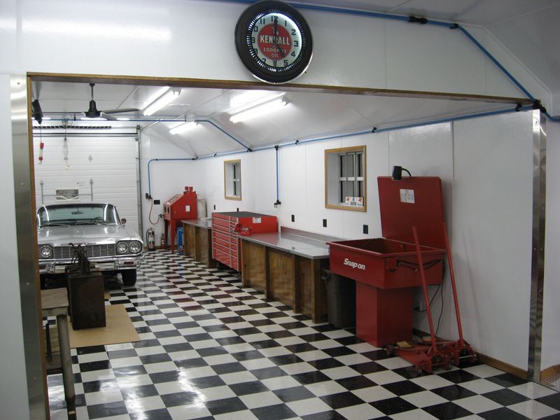
Normal framing with screws used on the 2 X 4's and the legs were bolted on. The ratchet straps were used to keep everything square. The quality of the material these days is awful. It will really move around if you don't stop it! This is the 8 foot bench, 3 legs. BTW these pictures were taken with the same 35MM camera as the earlier interior pictures. Notice how much better the quality is with proper lighting?!
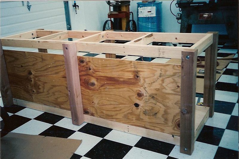
I put floors in them and backs on them as well. It not only finishes them off nicer but helps stiffen them up and keeps them square. 3/4" floors and 1/2" backs.
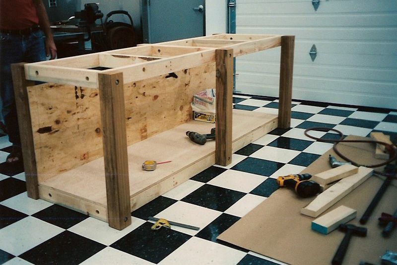
Here you can see how the legs were attached to the frames. In the short horizontal 2 X 4's I bored a 1" hole in the side. See that the top and bottom, end 2 X 4's have a hole in their sides. It's toward each end of the 2 X 4 near the legs. Then I bored a hole the diameter of the bolt through the leg and end of the 2 X 4 into that 1" hole. I took a piece of 1" electrical conduit pipe and cut a piece the width of the 2 X 4. That was then cut in half leaving two 1/2 circle pieces which had a hole drilled in them the diameter of the bolt. This was used as a wide washer inside the 2 X 4 so when the nut was drawn up on the leg bolt, it wouldn't split the 2 X 4. Pretty clear, huh?? I'll get a close up picture of another bench and post it if some wants to see that detail.
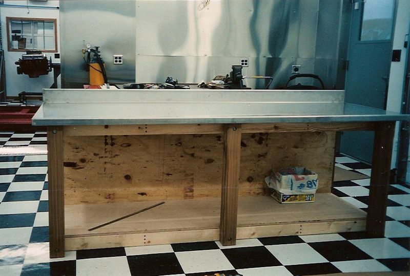

The end caps have been welded on the top and see how much better that finishes it off rather than just having the thin metal of the tops showing? A casual glance and the top appears to be all metal 1 1/2 " thick. Visually adds heft.

Here the benches are laying on their backs, bottoms toward each other. The end panels have been attached as well as the finished wood that covered the 2 X 4's on the face between each leg. The end panels and doors were 7 ply 3/4" Baltic birch plywood, the face wood was some sycamore I had.

Notice the bench at the top. On the right end you can see inside it has an extra pair of legs inside that end cabinet and no floor at that end. Hold that thought, we'll come back to it in a moment.

I had door panels laying all over the shop! I had to stain and then finish with gloss polyurethane. I sanded between each coat and got a creditable finish. 3 coats only, just a work bench not a piece of furniture.

Now I know you're looking at the end of that bench and have noticed it's a jolly big notch in it. Again hold that thought.

Here is the process of tig welding the end caps on and around the big notch.

See how the front of the top is bent all the way around to form a C in profile. Note the work area, out under my car port in front. This on of my favorite work spots. Outside with loads of natural light but sheltered just the same.

This is a temporary bench that will soon be replaced with the notched bench.


OK in this picture we've got a couple of things to point out. First off if you would go back to post # 181 ( it's on page #10 ) and scroll to the last picture of that series on lift repair. It's the one of my son sitting on top of the lift cylinder up in the air. Note when you're there that he is sitting on top of a big hunk of metal which is sitting on the lift cylinder. Also note that the chunk of metal just happens to be the size of this notch. Go ahead and look right now, I'll wait for you.............
..............OK that is a piece of steel 18" X 27" X 1 1/2" thick he's sitting on, flat both sides which was just laying around the shop waiting for me to find it and do something with it. I hung on to it knowing it would come in handy at some point. It occurred to me that my benches would have tops of 1 1/2" thickness. Why not incorporate that steel into the tops? Why not indeed and so here you are. See in the back two more 4 x 4 legs. Those are the ones you saw with the bench laying on it's back a few pictures back. That's to support that steel plate in all 4 corners. In addition there are two curved notches in the back edge. That's to provide room to install the bolts which tie the steel to the top. The wood substrate is two pieces of 3/4" particle board. I used that as underlayment to back up the stainless tops. It helps the tops resist denting, makes them feel real solid, keeps them from sounding tinny and adds weight for stability plus it's cheap too!

The edge of the notch is faced with stainless like the ends. It strengthens up the notch area and provides an edge to bolt the steel plate to.

Here's that chunk of steel, don't know what it weighs but I can just barely move it. Really takes two people to handle it safely. Those are the two bolts sticking out of the edge. I just tapped the steel to receive the bolts. The bolts are stainless steel too. I painted the plate so it wouldn't rust and look nasty.
Now I have a large, solid corner surface for those times you just need to beat the living tar out of something and not mar up the nice tops.
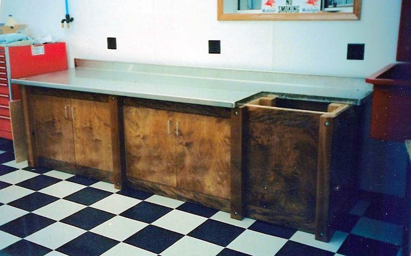
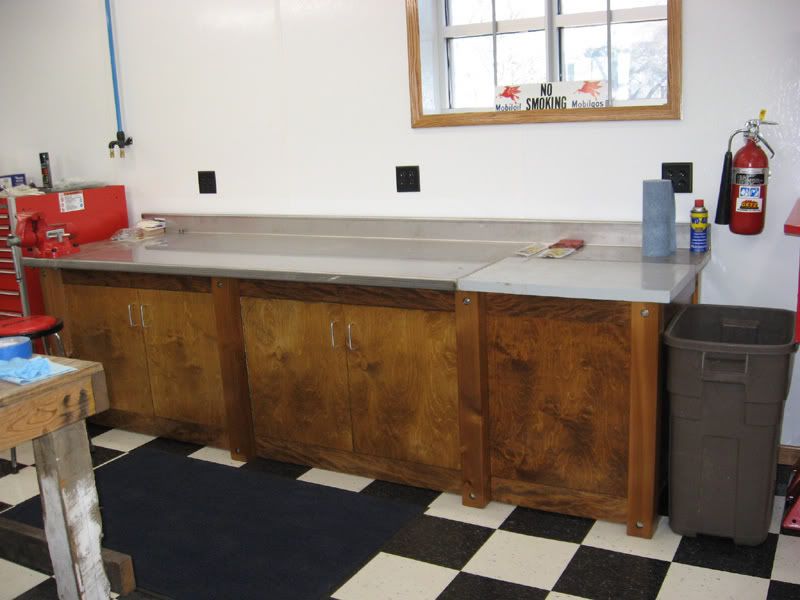
The doors were hung with stainless steel piano hinges and also incorporate touch latches so you can bump the door open with you knee should your hands be full. The wood you visually see is cedar legs, birch doors and sycamore horizontals between the legs. I managed to get them to stain up fairly close in color. This post may have been long but I hope you found it informative. The other two benches are in the next post.
Thomas
This is the pile of material I started with. Those are the sheets of 1/4" Masonite as well as card board I used to protect the tile floor.
Fabricating in the fabrication room!! I build three benches, 2 - 10' long and 1 - 8' long. The 10 footers had 4 legs across as seen here and the 8 footer had 3. Legs were 4" X 4". The floor tiles are 1 foot square so that helped with the general lay out. Piled in the background are the bench tops. I had a local machine shop bend them up for me. I had the front edge bent all the way under the front lip so if you clamp something along the front edge the bottom of the clamp would be bearing on metal and not on the bottom edge of the wood substrate. I also had a 4" back splash with a top edge on it to prevent objects from rolling off the back. I used 12 gauge stainless steel which is pretty thick metal. That should resist denting over the years and of course they can't rust. Also see that the ends are unfinished so I had end caps in the profile of the tops made which were tig welded to the edges to finish it off. I didn't want the wood substrate seen from an end view. They could bend 10' long, 12 gauge stainless and give me a 1/2 lip on top of the back splash. Pretty nice piece of work. They needed to use a hydraulic brake to bend them.
Normal framing with screws used on the 2 X 4's and the legs were bolted on. The ratchet straps were used to keep everything square. The quality of the material these days is awful. It will really move around if you don't stop it! This is the 8 foot bench, 3 legs. BTW these pictures were taken with the same 35MM camera as the earlier interior pictures. Notice how much better the quality is with proper lighting?!
I put floors in them and backs on them as well. It not only finishes them off nicer but helps stiffen them up and keeps them square. 3/4" floors and 1/2" backs.
Here you can see how the legs were attached to the frames. In the short horizontal 2 X 4's I bored a 1" hole in the side. See that the top and bottom, end 2 X 4's have a hole in their sides. It's toward each end of the 2 X 4 near the legs. Then I bored a hole the diameter of the bolt through the leg and end of the 2 X 4 into that 1" hole. I took a piece of 1" electrical conduit pipe and cut a piece the width of the 2 X 4. That was then cut in half leaving two 1/2 circle pieces which had a hole drilled in them the diameter of the bolt. This was used as a wide washer inside the 2 X 4 so when the nut was drawn up on the leg bolt, it wouldn't split the 2 X 4. Pretty clear, huh?? I'll get a close up picture of another bench and post it if some wants to see that detail.
The end caps have been welded on the top and see how much better that finishes it off rather than just having the thin metal of the tops showing? A casual glance and the top appears to be all metal 1 1/2 " thick. Visually adds heft.
Here the benches are laying on their backs, bottoms toward each other. The end panels have been attached as well as the finished wood that covered the 2 X 4's on the face between each leg. The end panels and doors were 7 ply 3/4" Baltic birch plywood, the face wood was some sycamore I had.
Notice the bench at the top. On the right end you can see inside it has an extra pair of legs inside that end cabinet and no floor at that end. Hold that thought, we'll come back to it in a moment.
I had door panels laying all over the shop! I had to stain and then finish with gloss polyurethane. I sanded between each coat and got a creditable finish. 3 coats only, just a work bench not a piece of furniture.
Now I know you're looking at the end of that bench and have noticed it's a jolly big notch in it. Again hold that thought.
Here is the process of tig welding the end caps on and around the big notch.
See how the front of the top is bent all the way around to form a C in profile. Note the work area, out under my car port in front. This on of my favorite work spots. Outside with loads of natural light but sheltered just the same.
This is a temporary bench that will soon be replaced with the notched bench.
OK in this picture we've got a couple of things to point out. First off if you would go back to post # 181 ( it's on page #10 ) and scroll to the last picture of that series on lift repair. It's the one of my son sitting on top of the lift cylinder up in the air. Note when you're there that he is sitting on top of a big hunk of metal which is sitting on the lift cylinder. Also note that the chunk of metal just happens to be the size of this notch. Go ahead and look right now, I'll wait for you.............
..............OK that is a piece of steel 18" X 27" X 1 1/2" thick he's sitting on, flat both sides which was just laying around the shop waiting for me to find it and do something with it. I hung on to it knowing it would come in handy at some point. It occurred to me that my benches would have tops of 1 1/2" thickness. Why not incorporate that steel into the tops? Why not indeed and so here you are. See in the back two more 4 x 4 legs. Those are the ones you saw with the bench laying on it's back a few pictures back. That's to support that steel plate in all 4 corners. In addition there are two curved notches in the back edge. That's to provide room to install the bolts which tie the steel to the top. The wood substrate is two pieces of 3/4" particle board. I used that as underlayment to back up the stainless tops. It helps the tops resist denting, makes them feel real solid, keeps them from sounding tinny and adds weight for stability plus it's cheap too!
The edge of the notch is faced with stainless like the ends. It strengthens up the notch area and provides an edge to bolt the steel plate to.
Here's that chunk of steel, don't know what it weighs but I can just barely move it. Really takes two people to handle it safely. Those are the two bolts sticking out of the edge. I just tapped the steel to receive the bolts. The bolts are stainless steel too. I painted the plate so it wouldn't rust and look nasty.
Now I have a large, solid corner surface for those times you just need to beat the living tar out of something and not mar up the nice tops.
The doors were hung with stainless steel piano hinges and also incorporate touch latches so you can bump the door open with you knee should your hands be full. The wood you visually see is cedar legs, birch doors and sycamore horizontals between the legs. I managed to get them to stain up fairly close in color. This post may have been long but I hope you found it informative. The other two benches are in the next post.
Thomas


")


