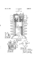
Once the head was off I made some measurements and made some calculations:
- Stroke order 1-2-4-3 stroke, 1 fill and 1 compression per stroke (like a 2 cycle gas engine)
- Piston Diameter D: 1.370 inches
- Piston Stroke S: 1.690 inches
- Displacement V: ((D/2)^2)*PI*S*4 = 9.97 CuIn
- CFM raw @ 1000RPM: (V*1000)/(12^3) = 5.77 CFM
Not bad at all!
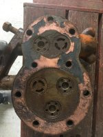
I also noticed that with the existing motor rotation, considering the pulley fan blade orientation, the pump pulley fan PULLS air instead of pushing it, which seems odd. Any ideas? I've seen a video here showing the same
clockwise rotation, so I guess it's supposed to be that way, but I am still puzzled, since improper rotation would starve the engine bearings of oil (remember, it's forced lubrication)... I guess that will be discovered only when I take it apart and I hesitate since I don't have a piston ring compressor...
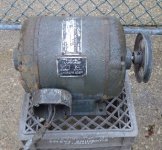
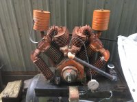
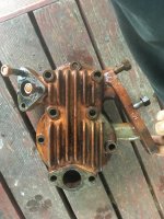
Here's a picture of the compressor:
Compare the pulley fan blade pitch with the one in the ad:
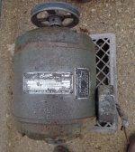
And here is a video clearly showing the same compressor as filmed by a youtube user: Notice the fan is oriented exactly the same as mine and rotates clockwise (best seen at the end of the video)
Here's a screen grab from that machine showing the fan blade orientation is the same as on my machine (enhanced from the video):


")