To avoid these ads, REGISTER NOW!

Quincy 325-12 - Bought Sight Unseen - Pics Inside

bpankratz

Banned
Joined
Dec 14, 2012
Messages
271
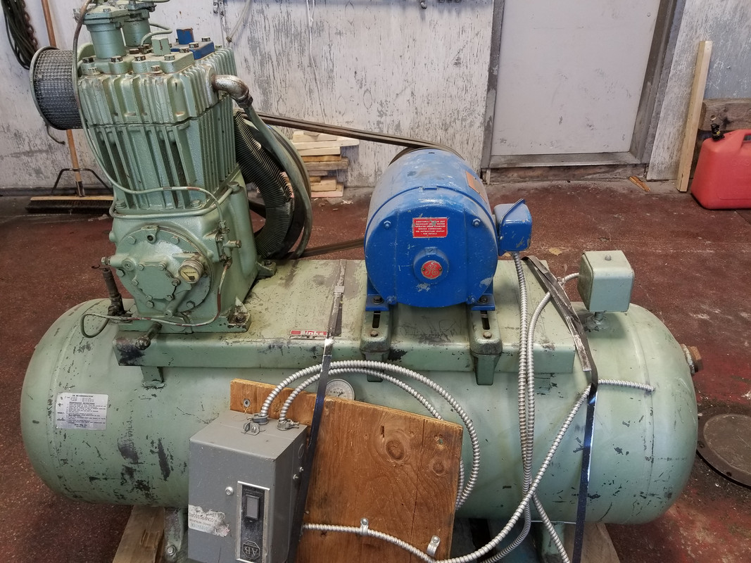
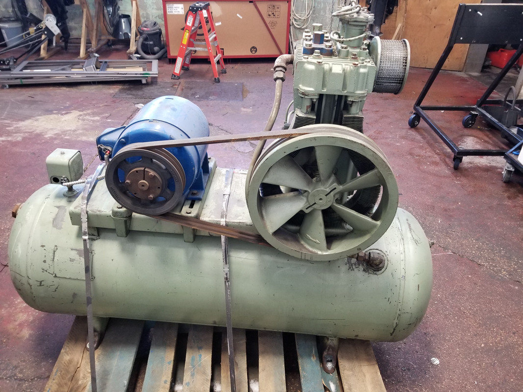
So I bought a new to me compressor. All I knew was it was a Quincy. I got it for about $500USD, plus $300 shipping. It came with a 5hp 3-phase motor. It showed up today, and I know nothing about this thing, I have a 7.5hp single phase motor to put onto it. Anything I should be looking for or doing to it? What sort of output can I expect? I would like to make it into a vertical unit, but I will need to locate a tank first, maybe get this one modified?


https://treetop100babynames.com/1000-popular-baby-names-1970-1979

 
To avoid these ads, REGISTER NOW!

nadogail

Well-known member
Joined
Jan 23, 2009
Messages
32,278
Location
Coronado, CA
IMHO, Charge the tank with air and check for leaks.
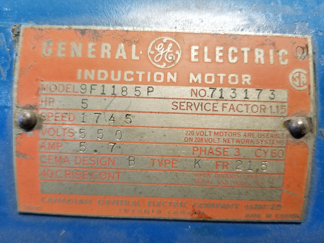
Your replacement motor RPM should match or approximate the 1745 of the original. Hopefully the motor shafts will be the same diameter and of equal length.
If all of it fits together mechanically, replace the oil in the compressor sump, then while watching for smoke, start the motor and pressure test the tank.
 
OP
B

bpankratz

Banned
Joined
Dec 14, 2012
Messages
271
IMHO, Charge the tank with air and check for leaks.
Your replacement motor RPM should match or approximate the 1745 of the original. Hopefully the motor shafts will be the same diameter and of equal length.
If all of it fits together mechanically, replace the oil in the compressor sump, then while watching for smoke, start the motor and pressure test the tank.

Thanks for the advise, I will do that once I get my new motor on there. The oil looks pretty clean so either it wasn't used much or was recently changed.
 
OP
B

bpankratz

Banned
Joined
Dec 14, 2012
Messages
271
Wow, $800 sight unseen. Is it worth like 10 times that?

I'm not sure what you are getting at. I live in an area where these things are non-existent, and if they do exist they are double that. Most of the pumps I have looked at alone are that much, and this one came motor, tank, pump, and magnetic switch so it seemed like a fair price.
 

pcmeiners

Well-known member
Joined
Aug 13, 2009
Messages
8,085
Location
In the only town in Pennsylvania, Bloomsburg.
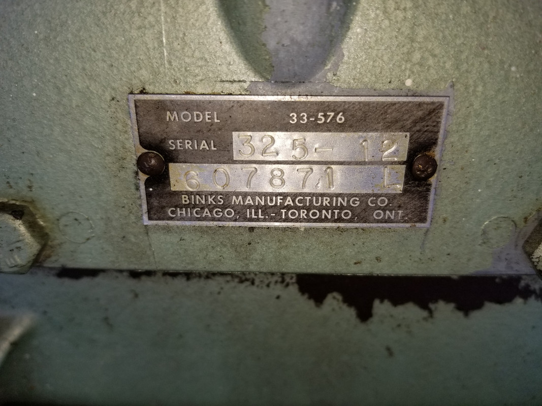
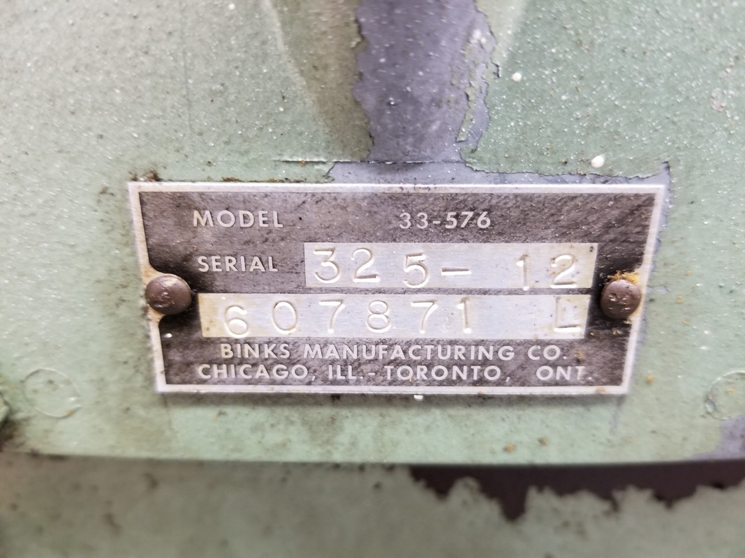
Believe it is a 1971 , the -12 is the record of change. For the very least, get to the oil filter screen and clean that (refer to a 325 manual for location). Definitely take the valves apart, clean them up, they may need some honing on wet/dry sand paper. As to the tank, what year was it manufactured? Seems pretty old. CFM 18 cuft, ,unless you change pulleys and increase rpm it will be 18cuft. Increasing rpm is not recommended. You will need a a motor starter.

Quincy site has a lot of manuals

http://mi-air.com/wp-content/uploads/2017/02/QR25-009-0515.pdf
 
Last edited:
OP
B

bpankratz

Banned
Joined
Dec 14, 2012
Messages
271
Believe it is a 1971 , the -12 is the record of change. For the very least, get to the oil filter screen and clean that (refer to a 325 manual for location). Definitely take the valves apart, clean them up, they may need some honing on wet/dry sand paper. As to the tank, what year was it manufactured? Seems pretty old. CFM 18 cuft, ,unless you change pulleys and increase rpm it will be 18cuft. Increasing rpm is not recommended. You will need a a motor starter.

Quincy site has a lot of manuals

http://mi-air.com/wp-content/uploads/2017/02/QR25-009-0515.pdf

Thanks for all of that, I'll have to check it out. I would like to do a full restoration of it one day, but for now I need. To get it pumping air. I'll check out the manual and do the maintenance before running it.
 

trbomax

Well-known member
Joined
Mar 21, 2010
Messages
2,556
Location
starvation lake,mi.
Thanks for the advise, I will do that once I get my new motor on there. The oil looks pretty clean so either it wasn't used much or was recently changed.

Compressor oil does not get dirty like lube oil in a internal combustion engine because there is no Combustion" taking place and therefore no carbon contamination the oil.The compressor oil does not get hot enough to carbonize either.The only contamination to be found in compressor oil would be metallic particles from wear in a moving part.This does not mean that compressor oil should not be analyzed because metallic wear particals from bearings and piston rings would normally be too small to see.You should run the unit up to normal operating temp, then drain a smalll quantity of oil.Send this oil out to be analyzed,I always used Blackstone Labs in Cleveland Ohio,but there are others.You could then finish draining the oil. If possible, shine a small light or a lighted borescope into the oil sump and look for visual signs of metal.If the oil sump looks clean replace the plug and wait for the results of the analysis.If all turns out well,I would refill with either Sunsco or Amzoil Compressor (synthetic)oil of the viscosity recommended by Quincy for your model. My Type 30 IR was built in 1933.My dad bought it new for a job shop he owned.It has never been apart for anything, but when I inherited it in 1973 I am sure it had the original mineral oil in it.My dad RIP was not much on equipment maintenance. None the less I drained it and refilled with Amsiol 30 wt and ran it another40 years!When I built the new shop in 2004 I serviced it in the way described above with Amsoil 40 wt synthetic compressor oil.It took over 70 yrs for that old Type 30 to get properly lubed,bu now, another 14 yrs later, it still has never been apart and ticks them off just fine.I did obtain another compressor,a Saylor Beall on a 100 gal upright receiver. It was built in the "50s and it runs fine to. I alternate them so I can always depend on having lots of air available!
 
Last edited:
OP
B

bpankratz

Banned
Joined
Dec 14, 2012
Messages
271
Compressor oil does not get dirty like lube oil in a internal combustion engine because there is no Combustion" taking place and therefore no carbon contamination the oil.The compressor oil does not get hot enough to carbonize either.The only contamination to be found in compressor oil would be metallic particles from wear in a moving part.This does not mean that compressor oil should not be analyzed because metallic wear particals from bearings and piston rings would normally be too small to see.You should run the unit up to normal operating temp, then drain a smalll quantity of oil.Send this oil out to be analyzed,I always used Blackstone Labs in Cleveland Ohio,but there are others.You could then finish draining the oil. If possible, shine a small light or a lighted borescope into the oil sump and look for visual signs of metal.If the oil sump looks clean replace the plug and wait for the results of the analysis.If all turns out well,I would refill with either Sunsco or Amzoil Compressor (synthetic)oil of the viscosity recommended by Quincy for your model. My Type 30 IR was built in 1933.My dad bought it new for a job shop he owned.It has never been apart for anything, but when I inherited it in 1973 I am sure it had the original mineral oil in it.My dad RIP was not much on equipment maintenance. None the less I drained it and refilled with Amsiol 30 wt and ran it another40 years!When I built the new shop in 2004 I serviced it in the way described above with Amsoil 40 wt synthetic compressor oil.It took over 70 yrs for that old Type 30 to get properly lubed,bu now, another 14 yrs later, it still has never been apart and ticks them off just fine.I did obtain another compressor,a Saylor Beall on a 100 gal upright receiver. It was built in the "50s and it runs fine to. I alternate them so I can always depend on having lots of air available!

Thanks for the advice, I will update this thread as soon as I get it going.
 
OP
B

bpankratz

Banned
Joined
Dec 14, 2012
Messages
271
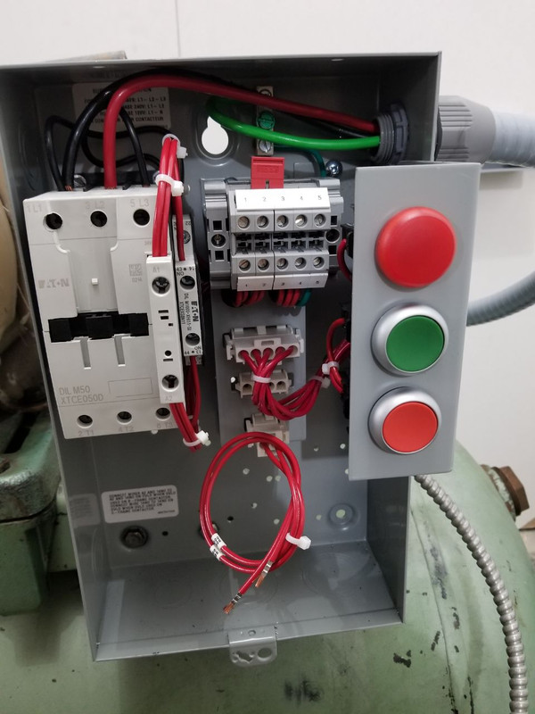
Ok so I need some help wiring my contactor. I bought an Eaton contactor, as far as I know it is the same as used on the current Quincy compressors. I also bought the optional on/off M22 switch so I can turn the compressor off when I am gone. (in case I have a leak and the pressure switch activates) my question is where to put the pressure switch wires? Any help is appreciated! Pics to follow.
 

matt_i

Well-known member
Joined
Mar 14, 2008
Messages
10,802
Location
SE Michigan
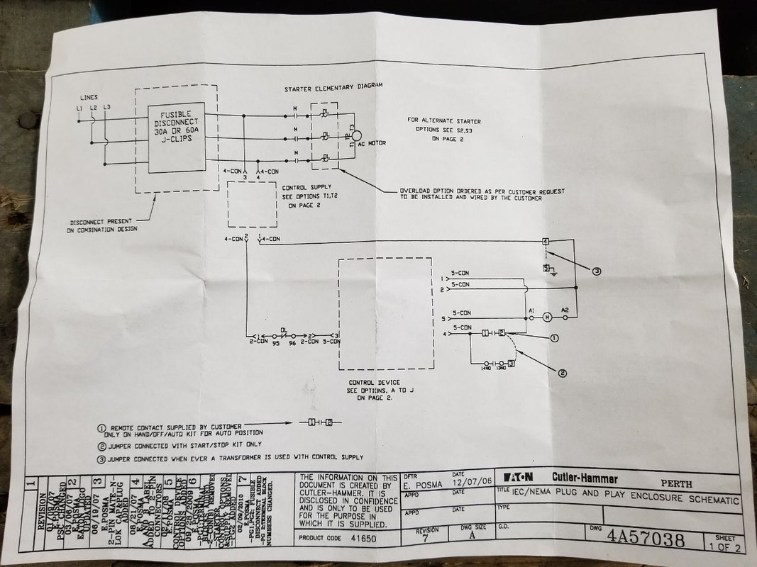
There are only a couple of connections to make. Input power to L1, L2. Then the motor itself, which would be T1, T2. The last connection is on the control side with the pressure switch itself, which I think is the large "magic box" at the center-bottom of page 1.

In essence on the control side, a pressure switch, a run/stop contact and the overload contact are all in series. Each one of those can stop the process, and all 3 have to be in the correct state for it to run.
 

tarmy

Well-known member
Joined
May 28, 2014
Messages
4,755
Location
Nor Cal
So the motor draws 5.7 amps...and is rated at 5hp...hmmm...

Seems like a 5 horse start up is going to be quite a bit of a spike...can somebody explain the low amp rating?
 
OP
B

bpankratz

Banned
Joined
Dec 14, 2012
Messages
271
So the motor draws 5.7 amps...and is rated at 5hp...hmmm...

Seems like a 5 horse start up is going to be quite a bit of a spike...can somebody explain the low amp rating?

Sorry guys, I wanted to clarify. The 5hp 575v motor has been removed, and replaced with a 240 single phase 7.5hp motor that draws 30a.
 
OP
B

bpankratz

Banned
Joined
Dec 14, 2012
Messages
271
There are only a couple of connections to make. Input power to L1, L2. Then the motor itself, which would be T1, T2. The last connection is on the control side with the pressure switch itself, which I think is the large "magic box" at the center-bottom of page 1.

In essence on the control side, a pressure switch, a run/stop contact and the overload contact are all in series. Each one of those can stop the process, and all 3 have to be in the correct state for it to run.

Ok, this all makes sense, , but seeing as this is a "plug n play" system I am unsure of where to wire the pressure switch to. I think it needs 120v on one side, and the "negative" hooked onto one of the terminals on the block labeled "1,2,3,4,5" but I am unsure of which one. The confusing thing to me is that big junction block. I get they are trying to make everything modular but now it's not clear what to hook where.
 
OP
B

bpankratz

Banned
Joined
Dec 14, 2012
Messages
271
Ok, so I feel like I'm getting somewhere, and nowhere at the same time. I found this pdf online. It tells you to buy a transformer, as well as the control kit. I have the control kit which is part number M22GK12PXPB, and the box I have is the EPX05K1T, so I think I need the 240 to 120VAC transformer.

Side note I feel like I have WAY over complicated this. I'm sure I could have found a contactor and put it in a box and wired it up for much less money with much less PITA, but this is what I have and it has been installed already so I can't bring it back.

LINK TO PDF:
https://www.google.com/url?sa=t&source=web&rct=j&url=http://www.eatoncanada.ca/ecm/idcplg%3FIdcService%3DGET_FILE%26allowInterrupt%3D1%26RevisionSelectionMethod%3DLatestReleased%26noSaveAs%3D0%26Rendition%3DPrimary%26dDocName%3DPCT_1623412&ved=2ahUKEwj7lLe6yIrhAhVStIMKHZdcBmQQFjACegQIBBAB&usg=AOvVaw3032jMFFtbaqoozHPUhgHP&cshid=1552877451229
 
To avoid these ads, REGISTER NOW!

Norcal

Well-known member
Joined
Mar 16, 2008
Messages
13,792
The wiring needs to be sized at 125% of NEC table 430.248 which lists a 7 1/2 HP motor as 40A @230V which would require conductors to be rated for 50 amperes, so 6/2 NM cable or 8 AWG THHN copper conductors.
 

matt_i

Well-known member
Joined
Mar 14, 2008
Messages
10,802
Location
SE Michigan
We need more info on what "options" this package has...its probably contained in the part number.

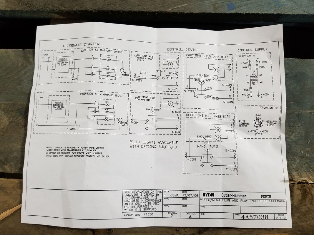
Hopefully you have option S2 which is the 240vac package. You have to install the looped wire from T2 to L3 so the overloads will not detect a phase loss. So correction from earlier, you wire input to L1, L2, and then wire the motor with T1, T3.


I couldn't tell if you have the control transformer (240:120) or not from your pictures. That would appear to be option T1.

Other than more pictures the only way to tell is to determine the coil voltage of the relay itself. That may be printed on it or you may have to google search the part number for the relay itself.

I'm not clear on which (E,F,G) option you have, schematically a green indicator light is shown which I don't think you have. The run/stop appears to be a maintained setup (rocker style) and not a seal-circuit involving the relay coil.
 
Last edited:
OP
B

bpankratz

Banned
Joined
Dec 14, 2012
Messages
271
The wiring needs to be sized at 125% of NEC table 430.248 which lists a 7 1/2 HP motor as 40A @230V which would require conductors to be rated for 50 amperes, so 6/2 NM cable or 8 AWG THHN copper conductors.

Ok, I think I amok on the wiring then, I have about a 50' run from my electrical box to the garage, and I used 6/3 NM, (don't ask why I did 6/3 and not 6/2), and then j have about 25' of #8 THHN from a junction box, directly to the contactor. You can see the THHN in my picture.
 
OP
B

bpankratz

Banned
Joined
Dec 14, 2012
Messages
271
OKAY NOW WE'RE GETTING SOMEWHERE!

We need more info on what "options" this package has...its probably contained in the part number.

Ok, so I have the box, and am wiring it for 240v so I will wire it like option S3. I also have option A or B for the control device, I'm not sure which one though, but I guess for the sake of the wiring diagram it does not matter.

Hopefully you have option S2 which is the 240vac package. You have to install the looped wire from T2 to L3 so the overloads will not detect a phase loss. So correction from earlier, you wire input to L1, L2, and then wire the motor with T1, T3.

Yes, that is how I am wiring it, just like S2

I couldn't tell if you have the control transformer (240:120) or not from your pictures. That would appear to be option T1.

I do not have any transformer yet, I did not know one would be required at the time of purchase. Correct me if I'm wrong, could I not use option T2 rather and just pull one of my 120v legs off of L1 or L2? Or is this a hack and I should just pony up and buy the transformer?

Other than more pictures the only way to tell is to determine the coil voltage of the relay itself. That may be printed on it or you may have to google search the part number for the relay itself.

10/4, I will do some research and better pictures as well.

I'm not clear on which (E,F,G) option you have, schematically a green indicator light is shown which I don't think you have. The run/stop appears to be a maintained setup (rocker style) and not a seal-circuit involving the relay coil.

The start / stop is definitely option A or option B, I'm not sure what the difference would be though.
 

metalmagpie

Well-known member
Joined
Nov 1, 2011
Messages
801
Location
Seattle
I used to own a Quincy 325-13.

You are going to replace a 5hp 3 phase motor with a 7.5hp single phase motor? Your 5hp 550V motor may well be able to be reconnected for lower voltage. Be aware the pump is probably set up to run at max rpm already. Don't exceed that. If a pulley on the new motor is bigger than the old, you would exceed that. Bad things.

Oil can certainly get contaminated. If your discharge valves leak a little then hot wet air will blow back through the pump and will drop water into the oil. You should change the oil at regular intervals as specified in the manual.

There is a series of 5 videos on YT that show how to dismantle and rebuild a Quincy 325. I don't know if all the parts are available still.

Find out where your local Quincy service center is. Go down there and meet the service manager. Get his business card. He is the guy you call with hard questions. He should know absolutely everything about your compressor. Always have your record of change number. Without it he won't be able to answer your questions. It's like calling a Plymouth dealer and asking what generator you need. If you don't know the model year, forget it!

Learn the Quincy online manual system and go download everything you can for your record of change (ROC) which is 12.

metalmagpie
 
OP
B

bpankratz

Banned
Joined
Dec 14, 2012
Messages
271
I used to own a Quincy 325-13.

You are going to replace a 5hp 3 phase motor with a 7.5hp single phase motor? Your 5hp 550V motor may well be able to be reconnected for lower voltage. Be aware the pump is probably set up to run at max rpm already. Don't exceed that. If a pulley on the new motor is bigger than the old, you would exceed that. Bad things.

Oil can certainly get contaminated. If your discharge valves leak a little then hot wet air will blow back through the pump and will drop water into the oil. You should change the oil at regular intervals as specified in the manual.

There is a series of 5 videos on YT that show how to dismantle and rebuild a Quincy 325. I don't know if all the parts are available still.

Find out where your local Quincy service center is. Go down there and meet the service manager. Get his business card. He is the guy you call with hard questions. He should know absolutely everything about your compressor. Always have your record of change number. Without it he won't be able to answer your questions. It's like calling a Plymouth dealer and asking what generator you need. If you don't know the model year, forget it!

Learn the Quincy online manual system and go download everything you can for your record of change (ROC) which is 12.

metalmagpie

Thanks for the advice. How do you suggest I reconnect the 575v motor for lower voltage? Both motors have the same RPM and pulleys so speed on the pump should be good, i can check with a laser tachometer too.

As far as downloading manuals I have not seen any service material for the 325. It seems Quincy has taken all their service material down, that is unless I am not looking in the right place?
 

matt_i

Well-known member
Joined
Mar 14, 2008
Messages
10,802
Location
SE Michigan
I did a little bit of simplification of the control side of the circuit.


Here's what I come up with...this is just a generic AC motor control station. Its not specific to an air compressor. When the Start is selected and the motor runs immediately (no pressure switch is integrated in their diagram) and the Red light comes on. When the motor stops due to the relay opening, the green light comes on. The Stop means basically "stop at this station" and the "remote device supplied by owner" can start it from another location...this is the Normally Open -][- contact to the right of #4 wire connection.

Here is how I would wire the thing if it were my own personal compressor....


If you don't have a control transformer, a 50VA model will do just fine. In this world, Stop means Stop with no option other than selecting Run button. The pressure switch needs to be integrated but I showed that. The only thing I didn't show was the light bulbs and those can basically be connected in any way you want. Green could mean the motor's running and red could mean the Start is allowing the pressure switch to control but the motor's not actually running yet. No lights means Stop is selected. I will draw in the bulbs when you tell me what you want it to do :)

Edit: whoops my start/stop selector switch symbology is messed up but I'll fix that later on.
 
OP
B

bpankratz

Banned
Joined
Dec 14, 2012
Messages
271
I did a little bit of simplification of the control side of the circuit.

Here's what I come up with...this is just a generic AC motor control station. Its not specific to an air compressor. When the Start is selected and the motor runs immediately (no pressure switch is integrated in their diagram) and the Red light comes on. When the motor stops due to the relay opening, the green light comes on. The Stop means basically "stop at this station" and the "remote device supplied by owner" can start it from another location...this is the Normally Open -][- contact to the right of #4 wire connection.

Here is how I would wire the thing if it were my own personal compressor....

If you don't have a control transformer, a 50VA model will do just fine. In this world, Stop means Stop with no option other than selecting Run button. The pressure switch needs to be integrated but I showed that. The only thing I didn't show was the light bulbs and those can basically be connected in any way you want. Green could mean the motor's running and red could mean the Start is allowing the pressure switch to control but the motor's not actually running yet. No lights means Stop is selected. I will draw in the bulbs when you tell me what you want it to do :)

Edit: whoops my start/stop selector switch symbology is messed up but I'll fix that later on.

First of all, thank you for taking the time to draw this out! I think this is making a lot more sense now. From what I gather you would run the transformer through the pressure switch, and back through the start stop, and then to the terminals 1 & 2. I'll grab a transformer today and let you know if I can figure it out Haha.
 

metalmagpie

Well-known member
Joined
Nov 1, 2011
Messages
801
Location
Seattle
Thanks for the advice. How do you suggest I reconnect the 575v motor for lower voltage? Both motors have the same RPM and pulleys so speed on the pump should be good, i can check with a laser tachometer too.

As far as downloading manuals I have not seen any service material for the 325. It seems Quincy has taken all their service material down, that is unless I am not looking in the right place?

Take the lid off of the junction box on the side of the motor and look to see if there is a diagram for changing voltages. If there are nine wires, it's a standard so even if there isn't a diagram you can do it anyway. Low voltage: 1-7, 2-8, 3-9, 4-5-6.

Although what "low voltage" means for a 550V motor I have no idea.

And yes, you are looking in the wrong place on the Quincy site.

metalmagpie
 

86turbodsl

Well-known member
Joined
Jul 1, 2005
Messages
6,564
Location
Michigan
So I bought a new to me compressor. All I knew was it was a Quincy. I got it for about $500USD, plus $300 shipping. It came with a 5hp 3-phase motor. It showed up today, and I know nothing about this thing, I have a 7.5hp single phase motor to put onto it. Anything I should be looking for or doing to it? What sort of output can I expect? I would like to make it into a vertical unit, but I will need to locate a tank first, maybe get this one modified?


The quincy 325 manual clearly states this is a 3-5hp pump. 7.5hp is overkill. Unless you already have it. Don't exceed the pump max rpm or you will blow it up.
 
OP
B

bpankratz

Banned
Joined
Dec 14, 2012
Messages
271
The quincy 325 manual clearly states this is a 3-5hp pump. 7.5hp is overkill. Unless you already have it. Don't exceed the pump max rpm or you will blow it up.

I don't plan on it, the motor was free, it will be spinning the same RPM as the previous 5hp motor.
 
OP
B

bpankratz

Banned
Joined
Dec 14, 2012
Messages
271
A little update, I have been very busy lately but had some time to work on it this afternoon. I had the compressor running, and it seems to build pressure very fast, which is excellent. I only had it running for about a minute as I have not had a chance to change the oil or check the true oil pressure (the factory gauge does rise a bit but not to the proper pressure).

I am still fighting with the contactor. I have it set up with the green "on" button, and the red "stop" button, which works, however I can't get the pressure switch wired in there properly. The problem is that the contactor kicks out anytime the control voltage is lost, and won't come back on until the green button is pressed again. I phoned Eaton, who wasn't a ton of help either. I'll get it, but it will take some more figuring and most likely a few components.
 

firebirdparts

Well-known member
Joined
Jun 8, 2016
Messages
10,756
Location
Kingsport, TN
That is Normal for most motor contactors. Most electric motors don’t start themselves. I guess you know that. This is kind of a special case where start stop buttons cannot work. You need a sustained run switch.
 
OP
B

bpankratz

Banned
Joined
Dec 14, 2012
Messages
271
That is Normal for most motor contactors. Most electric motors don’t start themselves. I guess you know that. This is kind of a special case where start stop buttons cannot work. You need a sustained run switch.

Yeah, I'm finding that out. Unfortunately I have purchased all of the components already. Like I said, I am sure I can figure it out, it might just take a little more. It would help if I actually knew what products were out there. I'm stabbing in the dark trying to figure out what products exist, and if they integrate with what I have.
 

Norcal

Well-known member
Joined
Mar 16, 2008
Messages
13,792
For a compressor, the starter needs to be wired for 2-wire control with the pressure switch, a 3-wire start/stop control station just does not work with a compressor because the pump will continue to run & then the safety pop off valve opens, and will not restart on its own. A selector switch could also be wired in the control circuit to shut off the compressor when not needed.
 

matt_i

Well-known member
Joined
Mar 14, 2008
Messages
10,802
Location
SE Michigan
For a compressor, the starter needs to be wired for 2-wire control with the pressure switch, a 3-wire start/stop control station just does not work with a compressor because the pump will continue to run & then the safety pop off valve opens, and will not restart on its own. A selector switch could also be wired in the control circuit to shut off the compressor when not needed.

This is the essence right here ^.

If you want to use a 3 wire control you'll need a separate relay to maintain the "seal circuit" for the Run state. Then the pressure switch is the only device in the chain that's setting the state of the motor ON or OFF. Until you get to the Stop state and then there will be 2 things missing from the chain, the "seal circuit" AND the pressure switch.

But 2 wire via a maintained selector switch or wall toggle is mechanically maintained in either Run or Stop states.
 
To avoid these ads, REGISTER NOW!
Top Bottom