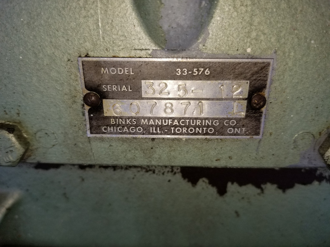
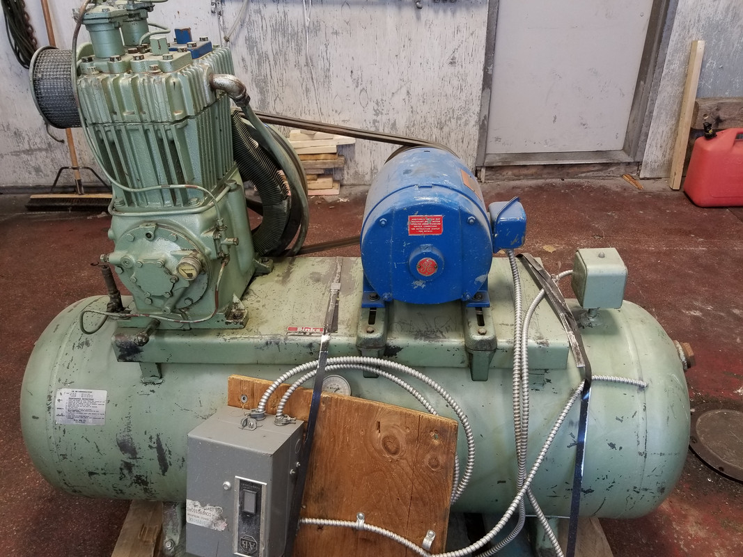
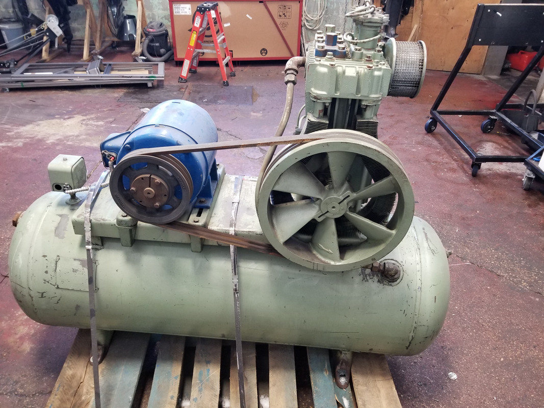
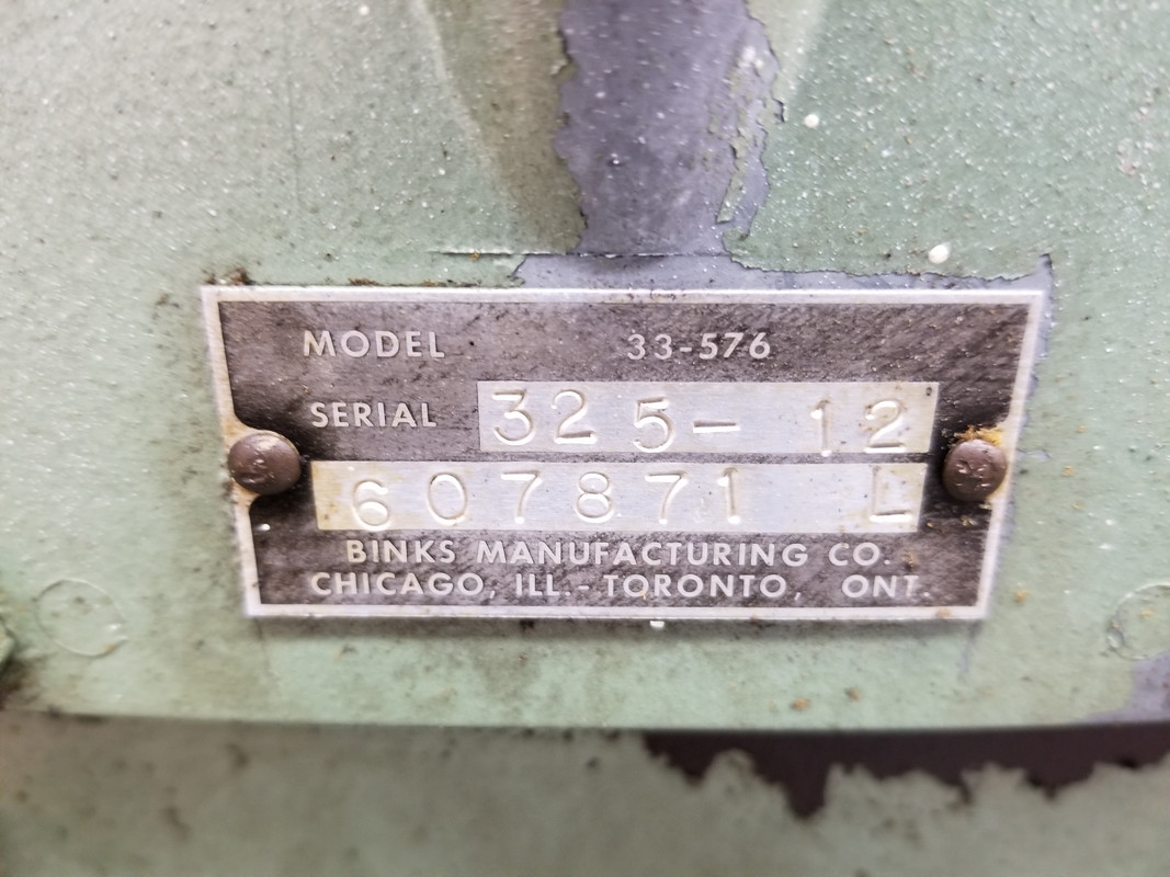
OKAY NOW WE'RE GETTING SOMEWHERE!
We need more info on what "options" this package has...its probably contained in the part number.
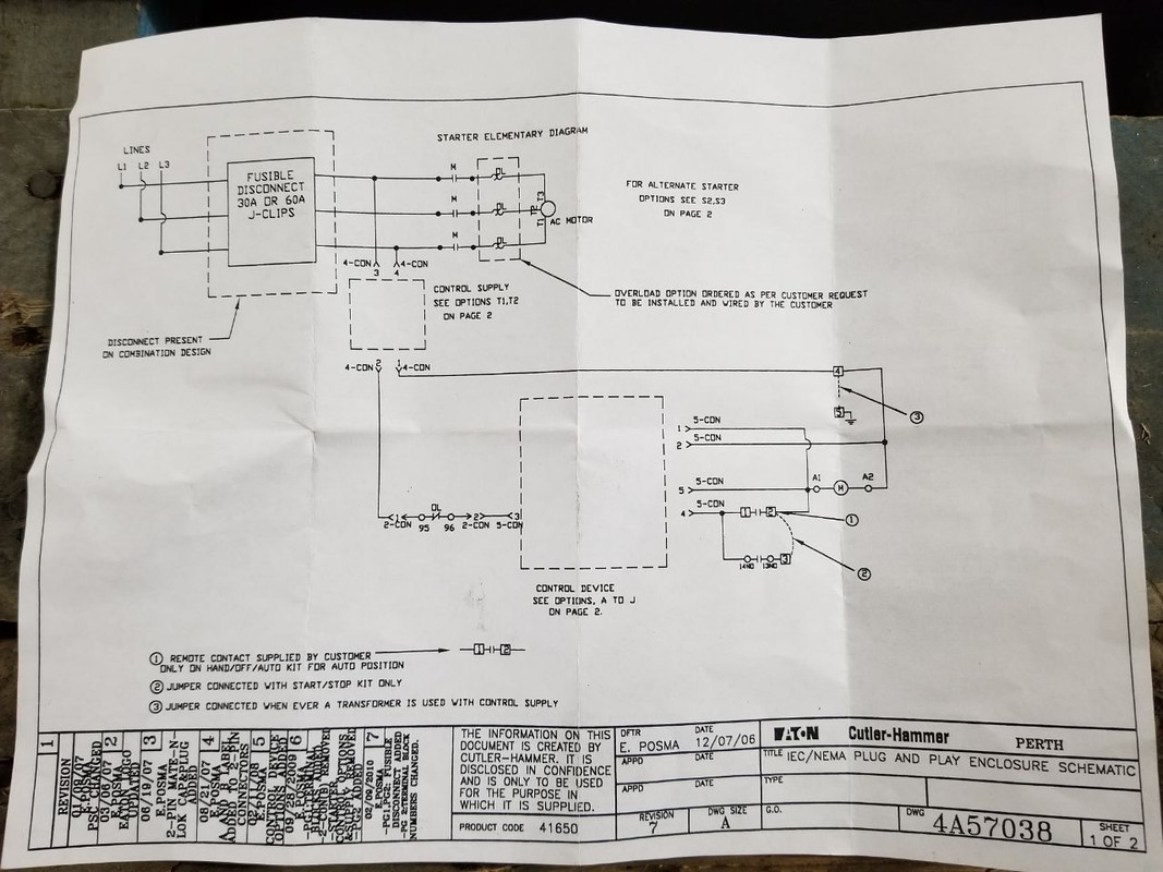
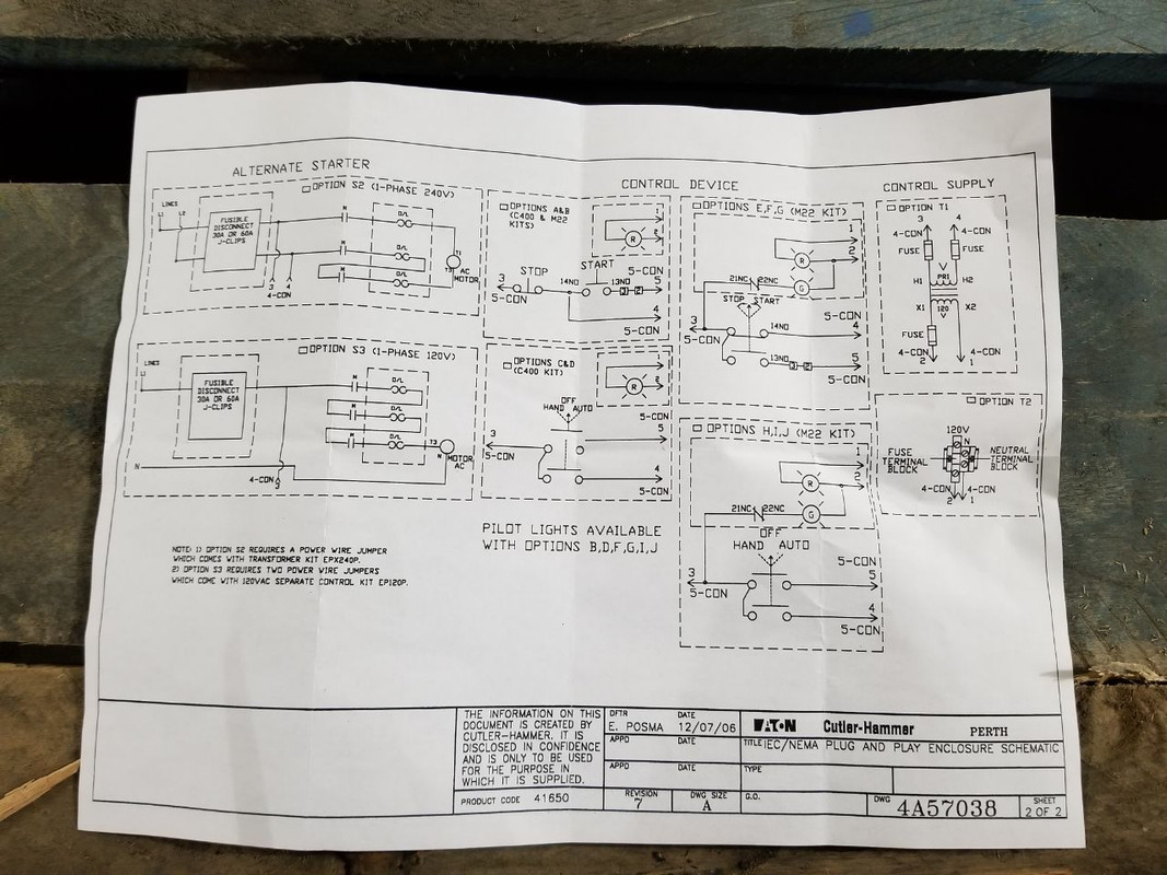
Ok, so I have the box, and am wiring it for 240v so I will wire it like option S3. I also have option A or B for the control device, I'm not sure which one though, but I guess for the sake of the wiring diagram it does not matter.
Hopefully you have option S2 which is the 240vac package. You have to install the looped wire from T2 to L3 so the overloads will not detect a phase loss. So correction from earlier, you wire input to L1, L2, and then wire the motor with T1, T3.
Yes, that is how I am wiring it, just like S2
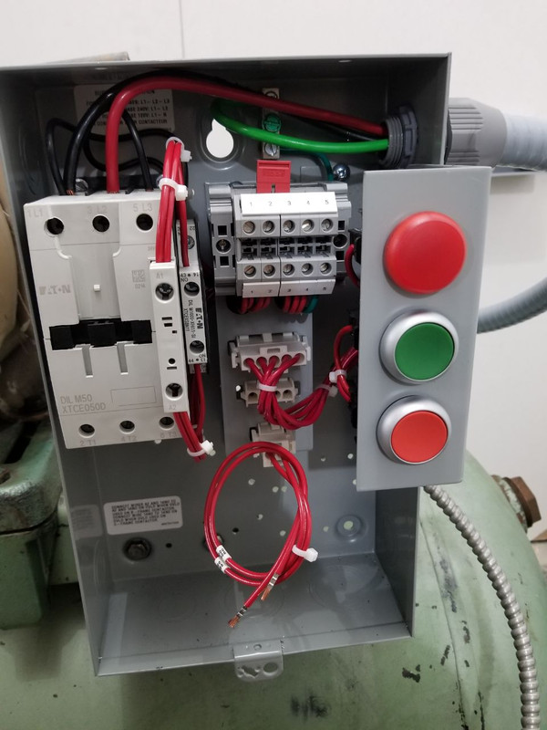
I couldn't tell if you have the control transformer (240:120) or not from your pictures. That would appear to be option T1.
I do not have any transformer yet, I did not know one would be required at the time of purchase. Correct me if I'm wrong, could I not use option T2 rather and just pull one of my 120v legs off of L1 or L2? Or is this a hack and I should just pony up and buy the transformer?
Other than more pictures the only way to tell is to determine the coil voltage of the relay itself. That may be printed on it or you may have to google search the part number for the relay itself.
10/4, I will do some research and better pictures as well.
I'm not clear on which (E,F,G) option you have, schematically a green indicator light is shown which I don't think you have. The run/stop appears to be a maintained setup (rocker style) and not a seal-circuit involving the relay coil.
The start / stop is definitely option A or option B, I'm not sure what the difference would be though.