To avoid these ads, REGISTER NOW!

Floor Jack Guru's: Vintage Hein Werner?

slackjaw

Well-known member
Joined
Jan 2, 2019
Messages
53
Location
San Francisco
Can anyone help ID this floor jack? I'm told it's a Hein Werner:

00e0e_5b12yErmMf1_1200x900.jpg


Looks similar to a model K, but the handle is straight and I haven't seen wheel covers on the handle side on other HW jacks in the past. The only marking I can find on it is "Made in USA" on the cylinder underneath.
 
To avoid these ads, REGISTER NOW!

isb cornbinder

Well-known member
Joined
Nov 3, 2010
Messages
7,073
Location
Pacific South West, BC, Canada
This is the Hein Warner I have. I don't like it and I never use it. This HW could use a heavy spring to control the handle. There is too much risk of the handle falling and hitting something important.
 

Attachments

  • HEIN WARNER JACK.jpg
    HEIN WARNER JACK.jpg
    52.2 KB · Views: 116
Last edited:

paulsomlo

Well-known member
Joined
Jul 16, 2013
Messages
3,911
Location
Northern Colorado
An SJ-1 will be 6 1/4" wide between the two side plates, an SJ-2 will be 7 1/8" wide (measure at the back).

I have a Sears trolley jack from the 80's, also 1 1/2 ton - when I put it next to my SJ-2, it looks like a toy. And the SJ-2 is roughly 3x the weight. That's what a real 1 1/2 ton jack looks like.

So, did you bring it home? Here's a link to the manual: https://www.hcrcnow.com/uploads/drawings/Blackhawk_SJ-2_Service_Jack_1.25_Ton.pdf

By the way, Photobucket blurred all my pics in the thread you linked - is there any way around that? Or do I have to upload them directly to GJ?
 
OP
S

slackjaw

Well-known member
Joined
Jan 2, 2019
Messages
53
Location
San Francisco
Thanks for the tip! Measures 7-1/8", so definitely an SJ-2.

I brought it home for $30. Ordered some seals from Lazzar (it's the same kit for the 1 and 2).

It's absolutely a beast of a 1-1/2 ton jack. One of things I noticed with newer floor jacks is they talk about lifting capacity as the weight of the car. Meaning if it's a 1-1/2 ton jack, and you lift the front corner of the car, the car shouldn't weigh more than 1-1/2 tons, which is a cop out in my book. Could be just a CYA safety thing, but regardless...

The odd thing about your thread is that one of the images looks fine, while the rest are blurry. If you can report or send me the originals, I'd appreciate it.
 

paulsomlo

Well-known member
Joined
Jul 16, 2013
Messages
3,911
Location
Northern Colorado
Here's the link to the originals on Photobucket, in the "Floor Jack" folder: https://s1095.photobucket.com/user/paulsomlo/library?page=1

Photobucket is holding my free acct hostage - try to ignore the photos of women in various states of undress, as well as the cat pictures. Basically, the thread you linked to details my efforts to convert from the original leather cup to a modern polyurethane ucup.
 
OP
S

slackjaw

Well-known member
Joined
Jan 2, 2019
Messages
53
Location
San Francisco
I only see a few of the photos from that page stored on PhotoBucket. Are you able to see all the first pictures (rod for example). I wonder if it's holding you ever more hostage than you think?
 

paulsomlo

Well-known member
Joined
Jul 16, 2013
Messages
3,911
Location
Northern Colorado
I went ahead and logged out, then tried the photobucket link - I can see all 23 pictures that are in there. In fact, there are four more than in my original post.

Have you gotten the hydraulics apart yet? The only challenge, really, is getting the tank nut off.
 

paulsomlo

Well-known member
Joined
Jul 16, 2013
Messages
3,911
Location
Northern Colorado
OK - I fixed the original thread, back to it's former glory (credit to TwoBytes). I won't be so foolish as to trust photobucket again.
 
OP
S

slackjaw

Well-known member
Joined
Jan 2, 2019
Messages
53
Location
San Francisco
Thanks, I can see it now. My kit shows up tomorrow, so I'll be tackling the whole thing, including the tank nut, this weekend.
 
OP
S

slackjaw

Well-known member
Joined
Jan 2, 2019
Messages
53
Location
San Francisco
Holy moly there was a heck of a lot of torque on that tank nut!

First I tried the trick Paul came up with in:
https://www.garagejournal.com/forum/showthread.php?t=232242&highlight=blackhawk

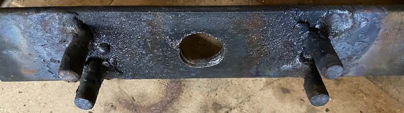
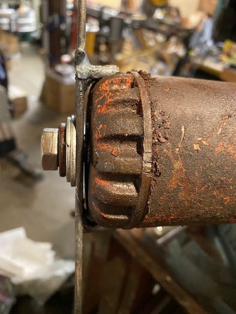
But the pipe wrench kept coming off when I put enough torque on it, so I resorted to quickly welding up some 1/4 steel pins onto a piece of 1/8" stock I had on hand, and using a 1/2-20 bolt to thread it into the end of the tank to keep it from coming off:

blackhawk-1.jpg

blackhawk-2.jpg


The bolt on the jack was too long, so I grabbed one from my local hardware store. The shortest I could find was 1", so I used a few washers and made it work.

Have no idea how I'm going to torque it up to the right amount or what the right amount is. I *think* I read 650 ft-lbs on another thread...
 

Roberts210

Well-known member
Joined
Dec 21, 2015
Messages
3,177
Location
Missouri
I torqued my tank nut off and on by making a tool from a 3/4 drive impact socket.

162541009.jpg


Then I used my Milwaukee impact wrench to take it off and torque it back on.

162585530.jpg
 

paulsomlo

Well-known member
Joined
Jul 16, 2013
Messages
3,911
Location
Northern Colorado
The manufacturers went to great lengths in the old days, to make sure that no one would attempt rebuilding their own jack. Modern jacks mostly use hex and square nuts on the tank - the manufacturers know that these days, nobody fixes anything, they just toss it and buy a new one.

Torque it down the best you can - try using some anaerobic sealant on the interface between the reservoir and the hydraulic body, as well as between the reservoir and the tank nut, just a thin layer on both ends of the reservoir. I think Hiball recommends Loctite 518.

So how's it look inside?
 

Roberts210

Well-known member
Joined
Dec 21, 2015
Messages
3,177
Location
Missouri
Hi Slackjaw. Which 3/4 socket did I use? A big one. Hahaha. Truthfully I don't remember the exact size, but it was metric and I got it for practically nothing. It was in the 2-1/2 inch range, whatever metric equivilant that would be. Yep, I welded that sucker together. As can be seen, I'm not a welder, but it stayed together. Later I cut it apart and made a socket out of it again.

162585532.jpg
 
OP
S

slackjaw

Well-known member
Joined
Jan 2, 2019
Messages
53
Location
San Francisco
Torque it down the best you can - try using some anaerobic sealant on the interface between the reservoir and the hydraulic body, as well as between the reservoir and the tank nut, just a thin layer on both ends of the reservoir. I think Hiball recommends Loctite 518.

So how's it look inside?

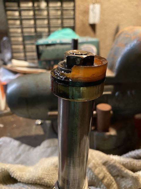
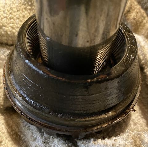
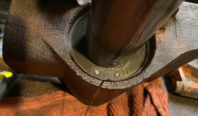
Not that bad. Looks like the plunger ring/cup fell apart, but otherwise ok.

blackhawk-int1.jpg

blackhawk-int2.jpg

blackhawk-int3.jpg


There also appears to be something falling apart where the cylinder meets the body. I assume from your comment about the reservoir to the body means I need to take that off. Tips on unscrewing it without marking it up?

I suppose I need to rebuild the pump too.
 
To avoid these ads, REGISTER NOW!

paulsomlo

Well-known member
Joined
Jul 16, 2013
Messages
3,911
Location
Northern Colorado
There also appears to be something falling apart where the cylinder meets the body. I assume from your comment about the reservoir to the body means I need to take that off. Tips on unscrewing it without marking it up?

I suppose I need to rebuild the pump too.

Are you talking about that stringy thing in the lower part of the picture? Someone may have rebuilt it prior and used some sealant. If you're asking whether you should remove the cylinder, I would say no - it's torqued about as much as the tank nut, and there's the danger of distorting it. If you can get the inside of the cylinder clean, there's really no reason to remove it. Now, given that the ram cup disintegrated, you'll need to do a thorough job of cleaning. That would entail opening up the release valve, the working valve, the pump, and maybe the overload valve. If you muck with the overload, the recommended procedure is to tighten it down until it stops, while counting the turns - that way, when you put it back together, you'll know where it needs to be set. I suppose, if you've got calipers, you can measure the depth to the adjusting slug and go by that. Yes, you should rebuild the pump, as well. In fact use up all of the "soft" parts included in the kit.
 
OP
S

slackjaw

Well-known member
Joined
Jan 2, 2019
Messages
53
Location
San Francisco
Are you talking about that stringy thing in the lower part of the picture? Someone may have rebuilt it prior and used some sealant. If you're asking whether you should remove the cylinder, I would say no - it's torqued about as much as the tank nut, and there's the danger of distorting it.

The stringy thing is what I was referring to. Wouldn't that have come from someone removing the cylinder in the past?

Now, given that the ram cup disintegrated, you'll need to do a thorough job of cleaning.

What would I clean with? I was only planning to replace the parts with what's in the kit.

That would entail opening up the release valve, the working valve, the pump, and maybe the overload valve.

How do I get the pump off. Do I just remove the retaining ring and set the cap free?

Sounds like I should avoid messing with the overload valve if I can. Though that would be counter to your advice of using up all the "soft" parts in the kit, right?

I'm not sure I understand the procedure. Are you saying I should tighten it down before taking it back?
 

paulsomlo

Well-known member
Joined
Jul 16, 2013
Messages
3,911
Location
Northern Colorado
The stringy thing is probably sealant residue from someone having removed the reservoir, which is the large diameter thin walled tube that came off when you unscrewed the tank nut. The cylinder is still screwed in to the hydraulic block, that's where the ram lives.

There are potentially, pieces of that ram cup throughout the hydraulics, you really should flush it out, or you may be doing this twice. You could probably use mineral spirits, whatever. If you use something like alcohol, remove any rubber or leather parts first. You can disassemble it - you won't need anything that's not included in the kit.

On the pump - yes, remove the retaining ring, remove the cap, be careful, as there's a large spring under the cap. Then, unscrew the hex nut and pull out the pump.

Regarding the overload valve - there aren't any soft parts in there, maybe a fiber washer under the head of the threaded plug. I'd say, leave the overload alone.

Regarding the working valve - I gather you mean the large slotted head screw; yes, that's the working valve.

Here's the parts diagram for the jack: https://www.hcrcnow.com/uploads/drawings/Blackhawk_SJ2_Service_Jack.pdf
 
OP
S

slackjaw

Well-known member
Joined
Jan 2, 2019
Messages
53
Location
San Francisco
Most of the ram cup is in a clump at the other side of the cylinder. But I get the idea of flushing to remove any tiny bits of residue. I’ll fill it with mineral spirits, shake it up and drain it.

I have been using that parts sheet; and it didn’t say working valve, which is why I confirmed.

I wish that screw was a bolt. I tried to get it off with a 1/2” screwdriver while taking it apart and it slipped and chunked off part of the metal on the head. I’ll have to get more creative...


Sent from my iPhone using The Garage Journal mobile app
 

HCRCnow

Well-known member
Joined
Oct 1, 2011
Messages
130
Location
Long Beach, CA
Hello, it is not necessary to remove the cylinder from the valve block. There is nothing in there to work on. Only remove the cylinder if it needs work you are not able to do while together. Really can not see the issue near the bottom.
 
OP
S

slackjaw

Well-known member
Joined
Jan 2, 2019
Messages
53
Location
San Francisco
Ok, only thing left are the two big o-rings. Looks like one is embedded in the tank but; but I can’t find the other one on the shaft. Not sure if it disintegrated (unlikely) or if it was rebuilt before and not used.

Anyone have a description or picture of where the other one should be?


Sent from my iPhone using The Garage Journal mobile app
 

paulsomlo

Well-known member
Joined
Jul 16, 2013
Messages
3,911
Location
Northern Colorado
Ok, only thing left are the two big o-rings. Looks like one is embedded in the tank but; but I can’t find the other one on the shaft. Not sure if it disintegrated (unlikely) or if it was rebuilt before and not used.

Anyone have a description or picture of where the other one should be?
I'm not sure that it's used on that jack. The drawing doesn't show it, and I can't figure out where it would go. Now, there was a version of the SJ-2 sold under the Sears name, and there are some differences between the Sears version and Blackhawk's version.

Maybe hcrcnow can shed some light.
 
OP
S

slackjaw

Well-known member
Joined
Jan 2, 2019
Messages
53
Location
San Francisco
Did you use either o-ring? I do see #1 in the picture embedded in #2 (the top cap). I assume you change that.

The other one I'm referring to is from:
https://www.hcrcnow.com/PDFs/Blackhawk_1_25_1_5_67401_SJ1_67402_SJ2.pdf

Now I'm not sure what the difference between these two jacks is, but mine matches the the page I just posted rather than the earlier link Paul posted. They're very similar of course.

The second o-ring I was referring to appears as #35 on this page, but I didn't see anything embedded in #36.
 
OP
S

slackjaw

Well-known member
Joined
Jan 2, 2019
Messages
53
Location
San Francisco
One interesting thing from the page Paul posted earlier, the notes refer to the plunger assembly #7 sold all together with parts starting with #8 (plunger ring), 18, 26, 13, 40, 44, 45, 7, and the cylinder. Looking at the diagram maybe everything is embedded/inside #7 and they just aren't shown separated out on Paul's page.

That said, again, I don't see the sliding spacer on Paul's, and it's definitely on mine. You can see the top of it on the first picture I posted earlier with the disintegrated cup.
 

paulsomlo

Well-known member
Joined
Jul 16, 2013
Messages
3,911
Location
Northern Colorado
I think I see what's going on - you've got the other version of this jack. Yours has the sleeve, which I believe prevents overextension. The other version, that has what you're referring to as "plunger assembly #7", has a more sophisticated method for preventing overextension. On your jack, you'll use orings #33 and 35.

Like I said, the parts kits are meant to cover slightly different versions of the same jack. Much easier to throw in an extra oring or two, than to maintain several different kits.
 
OP
S

slackjaw

Well-known member
Joined
Jan 2, 2019
Messages
53
Location
San Francisco
Interesting. That’s helpful.

However, still a bit stuck. My kit has 3 o-rings: 1/2”, 1-1/4”, and 1-5/8”.

33 is the 1-1/4” in the cap. 35 does not exist on my jack (unless it’s missing/disintegrated), and I assumed 7 on my parts sheet was the 1/2” in my kit. The 1/2” does look like it would fit as 35 on my jack.

I can’t see where the 1-5/8” would go on either — unless it’s 45 (retaining ring) on your jack.


Sent from my iPhone using The Garage Journal mobile app
 

paulsomlo

Well-known member
Joined
Jul 16, 2013
Messages
3,911
Location
Northern Colorado
Have your removed 37 yet? Is there an oring on the end of the ram (34), or a groove for an oring? It would be concealed by 37.

Does your pump rod (8) have an oring on it, or a groove for an oring?
 
OP
S

slackjaw

Well-known member
Joined
Jan 2, 2019
Messages
53
Location
San Francisco
Yes, I removed 37 and I didn't see an o-ring -- which is where I expected it. I'll double check tonight.

I just got 8 off. PITA, as there isn't an easy nut like with yours, and I had to play around with my vice to avoid slipping.
 
OP
S

slackjaw

Well-known member
Joined
Jan 2, 2019
Messages
53
Location
San Francisco
Ok, here's what I have now.

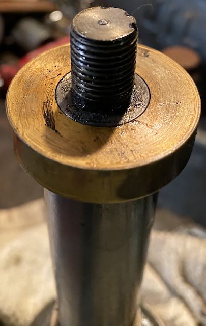
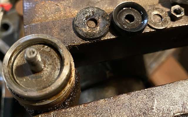
First, here's the plunger. No o-ring, but note the plunger wiper 38 that sits on it had a indent for what could have been an o-ring at some point, and the small o-ring from the kit would fit there.

cup-base.jpg

cup-washer-orig.jpg


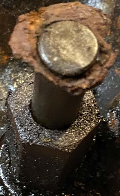
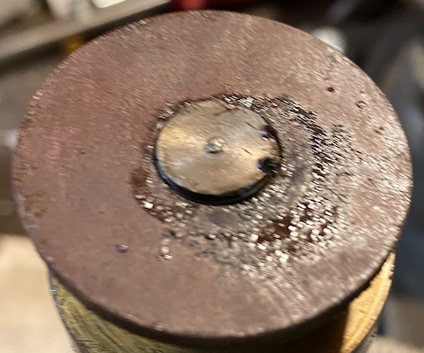
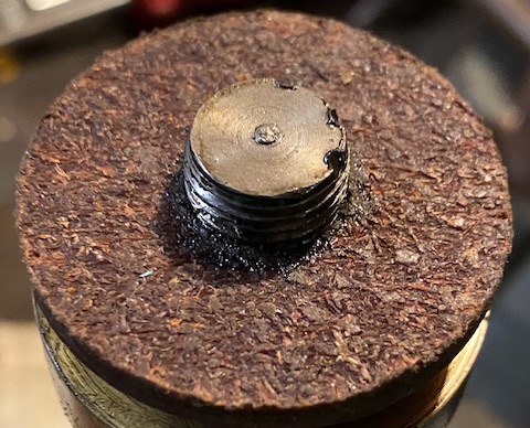
Here's the pump plunger when I took the spring and cap off. It has a groove for what could be an o-ring near the top, and it looks like a corroded something or other was there? I don't see anything matching this on the parts sheet.

piston-groove.jpg


Here's the pump apart. Parts go back on starting left to right. No o-ring in there as in the document, but the o-ring in the kit would also fit here.

pump-parts.jpg


Two other oddities with the replacement parts in the kit:

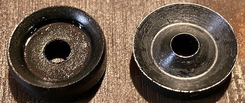
The original plunger cup 5 is flat inside but the replacement has a cone. Maybe the original was just really flattened over time?

plunger-cup.jpg


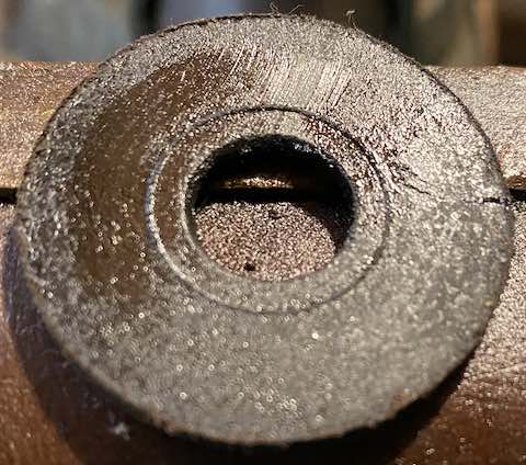
The original plunger wiper 38 is flat on both sides, whereas the replacement is flat on one side and rough on the other. Not sure which side goes down or why it's different.

cup-washer-flat.jpg

cup-washer-rough.jpg
 

paulsomlo

Well-known member
Joined
Jul 16, 2013
Messages
3,911
Location
Northern Colorado
You've got a little more disassembly to do; remove the brass thing 37 (heel plate) from the end of the ram, remove the pump piston from it's cylinder.

Not sure what your "corroded" thing is, possibly the underside of 10, the cap, got rusty.

Regarding 38, the wiper, looks like the original was smooth side down.

Plunger cup 5 is normal, mine are "coned" in the middle.

This picture should help:
 

Attachments

  • P1272792.JPG
    P1272792.JPG
    79.6 KB · Views: 23
To avoid these ads, REGISTER NOW!
Top Bottom