To avoid these ads, REGISTER NOW!

VISE REPAIR 101 all vise repairs, lubricants, sources for parts and the tricks to fix

To avoid these ads, REGISTER NOW!

Shiftless

Well-known member
Joined
Mar 9, 2014
Messages
14,580
Location
East Bay SFO
Drives:
Yes, you can definitely smell the odor of Simple Green when you heat it up. Less when the crock pot is covered as expected. To me, the odor is not objectionable. The garage in our house is connected but on a different level than the living space and separated by 2 store rooms, a staircase, and 3 closed doors.

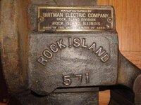
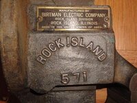
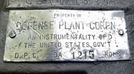
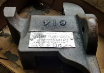
BTW, it’s Birkman Electric on that tag.
 
Last edited:

Mslund1

Well-known member
Joined
Feb 9, 2019
Messages
133
Location
Michigan
BTW, it’s Birkman Electric on that tag.[/QUOTE]


Actually it’s Birtman Electric

4396c84d60880a9c6844f880084b8c66.jpg


Sent from my iPhone using Tapatalk Pro
 

Attachments

  • 4396c84d60880a9c6844f880084b8c66.jpg
    4396c84d60880a9c6844f880084b8c66.jpg
    39.2 KB · Views: 3

Woodreaux

Well-known member
Joined
Sep 30, 2019
Messages
47
Location
Louisiana
Wood: your Great Grand dad's old vise looks like it's been to war and while it has some injuries if it works I'd say use it. that said do you have brazing skills or know a friend that does?

I haven't brazed anything before, but I go have a machinist friend who could help me. Would be a good way to learn as well. Its a skill I've wanted to gain

Sent from my Pixel 3 XL using Tapatalk
 

2oolhound

Well-known member
Joined
Dec 18, 2010
Messages
5,918
Location
BC Canada
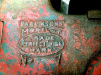
Welding Jaws on a Parkinsons’ “F” #7 Perfect Vise

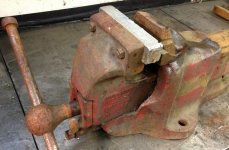
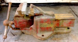
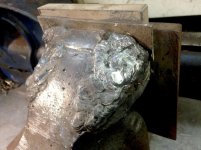
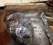
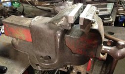
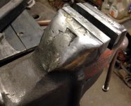
I’ve seen several youtube videos on welding repairs on vises but I’m no welder however the process intrigued me. So, when I came across this broken quick release vise at a scrap dealers I shelled out the $10 for it just to experiment. As you can see in the photos both sides have been broken off the static jaw across where the jaw face bolts holes are. My guess is the po was holding something with the outside edges of the jaws only and they broke off in 2 separate occasions. I’m providing lots of photos to show the design of the vise and the damage. This has been an ongoing project for almost a year now due to equipment issues.

attachment.php


attachment.php


attachment.php


attachment.php


attachment.php
 

Attachments

  • ParkinsonViseSm_3693.jpg
    ParkinsonViseSm_3693.jpg
    99.8 KB · Views: 269
  • ParkinsonSm_3692.jpg
    ParkinsonSm_3692.jpg
    61.6 KB · Views: 268
  • ParkinsonSm_3694.jpg
    ParkinsonSm_3694.jpg
    63 KB · Views: 266
  • ParkinsonSm_3702.jpg
    ParkinsonSm_3702.jpg
    85.3 KB · Views: 268
  • Parkinson's"F"ViseSm_3698.jpg
    Parkinson's"F"ViseSm_3698.jpg
    48.7 KB · Views: 266

2oolhound

Well-known member
Joined
Dec 18, 2010
Messages
5,918
Location
BC Canada
Since I’m only a crash boom bang novice welder (guy with a stick welder) my only hopes were to stick the ends back on and hope the jaws faces would distribute the pressures applied more evenly across the whole front of the vise. The other bad thing about me is I have no budget for this kind of thing and my rods are usually obtained at swap meets often in no packaging. :)

Anyway to prep I ground all the rusty and painted surfaces off with a die grinder. I’ve heard these Parkinson vises are cast steel but I still don’t know as I’m a novice at most of this.

attachment.php


I had the brilliant idea to sandwich a brass plate across the jaw face so I could weld up to it and keep the track for the jaw insert flat so no machining would be necessary.

attachment.php


After that and following my youtube learnings for repairing cast iron vises I baked in the oven slowly bringing the temperature up from 200’ all the way to 450’ over an 8 hour period. It came out a dark brown everywhere.

attachment.php


I ground all weld surfaces down again to remove this coating and commenced pouring rod into the broken areas. I did long consistent beads parallel to each other then peened while still hot and knocked all slag off then die ground again to remove impurities so my next weld passes would go on smoothly. I repeated this procedure until I’d built up the entire area that was missing. I also changed the style and shape of the static jaw so I would have to drill and tap into the body of the vise to attach the jaw faces instead of keeping the bolt through style it originally had. I felt this would be stronger. In these next 2 shots you can see the vise’s brain (normally under the top surface of a vise that you usually see).

attachment.php


attachment.php
 

Attachments

  • ParkinsonViseSm_3780 copy.jpg
    ParkinsonViseSm_3780 copy.jpg
    106.8 KB · Views: 263
  • ParkinsonViseSm_3782 copy.jpg
    ParkinsonViseSm_3782 copy.jpg
    145.3 KB · Views: 269
  • ParkinsonSm_3778.jpg
    ParkinsonSm_3778.jpg
    42.9 KB · Views: 265
  • ParkinsonViseSm_3724.jpg
    ParkinsonViseSm_3724.jpg
    106.4 KB · Views: 268
  • ParkinsonViseSm_3732.jpg
    ParkinsonViseSm_3732.jpg
    130.9 KB · Views: 264

2oolhound

Well-known member
Joined
Dec 18, 2010
Messages
5,918
Location
BC Canada
After I’d built up the broken off sections I removed my brass plate. Unfortunately I hadn’t pushed the rods in toward the brass plate enough to penetrate evenly up to the plate and there was a distinct line where my weld met the existing metal. Also a crack was revealed that I hadn’t seen earlier or I would have ground more to get up to it (it’s the line reaching toward the center on the left side). All I could do now was weld on this face which would require me to machine the jaw face afterwards. (I had no way to do this at the time). I’ve lost some photos of these last welds on the face but I made sure to get good penitration.

attachment.php


I tried filing the face many times doing 20 minutes here 20 minutes there but eventually gave up and decided I really needed a milling machine to finish the job. I’d been wanting one for years and even had a big stash of end mills and a space in my small shop reserved for one. Finally I closed a deal on a Rong Fu 30 mill drill. This was the 1st project after setting it up. Unfortunately milling the face wasn’t a cake walk, there was a hard bit of weld at the area of the crack and the end mill would slow down and finally get chewed up when it hit it. I ended up grinding it with a 1/4” die grinder stone on the mill and that only got me within .010 of flat across that hard spot until I broke all the grind stones I had.

attachment.php


I made up some aluminum jaw faces, drilled and taped the holes and used JB weld epoxy to fit them onto the face so that would take up the slack of my imperfect face. The other snag I hit was when I drilled to tap where the crack was (and the hard spot) my drill would not penetrate the hardened area. I tried to finish the hole with a 3/16” ball end carbide bit in my die grinder but it wouldn’t even touch the hardened area. I think some kind of hard surface rod was mixed in with my swap meet welding rods or it work hardened somehow. Maybe someone had better insight into this. For now that side has only a few threads and JB weld epoxy holding it in place but it’s been holding well for a month or more now. I cut a taper into the back side of the heads of allen head screws to get the proper tapered screws to secure the jaw faces.
I’ve been afraid to put it to the ultimate test and tighten something down till nearly bending the handle so I just use the vise as needed. I have cranked pretty hard on the vise with work centered but am a little unsure of what the sides will take. Time will tell. I’ll update this thread if I ever break an end off. (fingers crossed).

attachment.php


attachment.php


attachment.php


attachment.php
 

Attachments

  • ParkinsonSm_6005.jpg
    ParkinsonSm_6005.jpg
    60.8 KB · Views: 268
  • ParkinsonSm_6012.jpg
    ParkinsonSm_6012.jpg
    53.3 KB · Views: 268
  • ParkinsonSm_6004.jpg
    ParkinsonSm_6004.jpg
    54.9 KB · Views: 268
  • ParkinsonSm_5512.jpg
    ParkinsonSm_5512.jpg
    62.7 KB · Views: 271
  • ParkinsonViseSm_3787 copy.jpg
    ParkinsonViseSm_3787 copy.jpg
    102.1 KB · Views: 270
  • ParkinsonSm_6007.jpg
    ParkinsonSm_6007.jpg
    53.7 KB · Views: 265

Oregon rock crusher

Well-known member
Joined
Jun 28, 2016
Messages
1,913
Location
West of Salem
That came out really nice considering what you had to start with 2oolhound! Not many would have taken on that level of jaw tower repair. I've used your method of getting a flat jaw seat in the past by clamping in heavy copper bus bar stock with fairly good success. Never took on that much damage though, just a corner or too. Good job. Ed.
 

AngryBeaver

Well-known member
Joined
Jul 12, 2017
Messages
1,705
Location
Lake Milton Ohio
After I’d built up the broken off sections I removed my brass plate. Unfortunately I hadn’t pushed the rods in toward the brass plate enough to penetrate evenly up to the plate and there was a distinct line where my weld met the existing metal. Also a crack was revealed that I hadn’t seen earlier or..... <snip>


I'll give you an atta boy. most enthusiasts here are usually 100% against welding. I've welded ton of them now and have learned a metric **** ton. IT is very easy to overheat the casting when welding. this effectively causes a heat treat process to happen, especially when areas need alot of build up. Its a fine line between preheat, welding, and post heat to keep it from cracking, and then superheating it, effectively hardening it. I recently ran into this rebuilding broken off jaw towers on a Reed 3c. I used copper as a backer like you did with brass, and ran into severe hardening issues trying to file the corners of the jaw support.

I have tested a few welded vises with a 48oz ball peen until i was wore out from swinging. Not all castings are the same, even from the same manufacturer. ductile steel seems more susceptible to the hardening from my experience than cast. you probably had it a bit too hot, or didn't turn it down as you welded on it and it heated up.
 

Shiftless

Well-known member
Joined
Mar 9, 2014
Messages
14,580
Location
East Bay SFO
2oolhound:
Thanks for posting and sharing your experiences with that seemingly ruined vise.

And thanks A.B. for adding your sage advice to the thread.
 

ClappedOutBport

Well-known member
Joined
Mar 30, 2016
Messages
998
Very nice fix. I experienced some crazy hardening as well when doing tig Silicon Bronze brazing on cast. Ruined my endmills as well. I believe the high carbon content forms martensite when cooled rapidly at the weld zone.


Yeah, just googled:
The casting process is never perfect, especially when dealing with large components. Instead of scrapping defective castings, they can often be repaired by welding. Naturally, the very high carbon concentration of typical cast irons causes difficulties by introducting brittle martensite in the heat-affected zone of the weld. It is therefore necessary to preheat to a temperature of about 450°C followed by slow cooling after welding, in order to avoid cracking. The materials used as fillers during welding usually contain large nickel concentrations so that the resulting austenitic weld metal is not sensitive to the pick-up of carbon from the cast iron. The deposits are soft and can be machined to provide the necessary shape and finish. Of course, nickel is expensive so when making large repairs, the weld gap is first covered ('buttered') with the nickel-rich filler and then the remaining gap is filled with less expensive mild-steel filler metals.
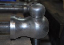
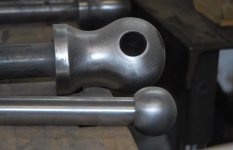
https://www.phase-trans.msm.cam.ac.uk/2001/adi/cast.iron.html


So that's the problem. It comes out like tool steel.


2oolhound

Well-known member
Joined
Dec 18, 2010
Messages
5,918
Location
BC Canada
Thanks for the comps guys and the info too. It was a long time coming but I'm loving this vise now(it's my 1st QR).

However I bought this one from the same junk dealer at the same time which is also quick release. All it says on it is Steel 10. It came from the same estate originally so I'm thinking it's UK also.

attachment.php


attachment.php
 

Attachments

  • Steel10Vise_5729.jpg
    Steel10Vise_5729.jpg
    47.6 KB · Views: 263
  • Steel10ViseSm_5730.jpg
    Steel10ViseSm_5730.jpg
    41.5 KB · Views: 269

KMScott

Well-known member
Joined
Feb 14, 2012
Messages
4,643
Location
Daufuskie Island, South Carolina
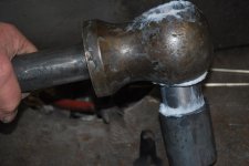
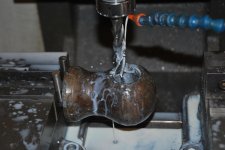
Here is a fix I did on a Prentiss 58 Spindle handle hole. The original was wallered to much and needed to be repaired. I bored the old handle hole out to accept a 1/4" wall sleeve. I purchased a piece of cast material from McMaster's and made the sleeve. Gave the sleeve about .010 clearance and silver soldered the sleeve in place using Easy Flow 45. Took plenty of heat and being patient is the key and it eventually soldered fine. Cleaned it up with my 36grit sanding disc and a hook and loop Scotch Brite pads mounted to my 4-1/2" angle grinder. Finished making a new 1-1/8 handle with 2" knobs. Should last another 75 years.
 

Attachments

  • Prentiss Meatball #23 (3).jpg
    Prentiss Meatball #23 (3).jpg
    110.3 KB · Views: 42
  • Prentiss Meatball #23 (1).jpg
    Prentiss Meatball #23 (1).jpg
    103.1 KB · Views: 45
  • Prentiss #58-Meatball (20).jpg
    Prentiss #58-Meatball (20).jpg
    101.8 KB · Views: 42
  • Prentiss #58-Meatball (16).jpg
    Prentiss #58-Meatball (16).jpg
    112.8 KB · Views: 39
  • Prentiss #58-Meatball (13).jpg
    Prentiss #58-Meatball (13).jpg
    108.5 KB · Views: 42
  • Prentiss #58-Meatball (9).jpg
    Prentiss #58-Meatball (9).jpg
    117.7 KB · Views: 42
  • Prentiss #58-Meatball (2).jpg
    Prentiss #58-Meatball (2).jpg
    103.6 KB · Views: 40

KMScott

Well-known member
Joined
Feb 14, 2012
Messages
4,643
Location
Daufuskie Island, South Carolina
Last edited:
OP
D

drivesitfar

Well-known member
Joined
Oct 23, 2013
Messages
36,062
Location
Pacific Northwest
2ool: awesome repair and thanks for sharing all the pictures and the process.

you mentioned heating in an oven do you have a shop oven or did you sneak inside your kitchen and use the family stove/oven or maybe you're single? also are you moving a 450 degree vise around with just welding gloves or did you move it another way?

as far as your unmarked vise it has all the looks of a European vice and a Parkinson, but your Canadian guys might have made it cause they seemed to like to copy some of the designs from the UK.

after all that welding and repair how do you like using your Parkinson and does the quick release work ok too?

WELL DONE!! :bowdown::bowdown:

Woodreaux: well perfect timing for 2oolhound to post up some cast iron welding isn't it? the first thing I've heard that you need to do on the slide after you clean it up very well is to maybe drill a hole at the end of the crack to stop the cracking. then cut a big V in the crack area to give you plenty of room for weld. since i'm not a welder others should chime in as to all the steps so if you plan on doing that just ask and maybe one of them will see your posts.

good luck!
 

gf0012-aust

Well-known member
Joined
Apr 17, 2011
Messages
172
Location
Adelaide
I had the brilliant idea to sandwich a brass plate across the jaw face so I could weld up to it and keep the track for the jaw insert flat so no machining would be necessary.

There’s a vise repair vid on YouTube of a bloke doing the same thing using square copper stock

Works a treat 😀
 

2oolhound

Well-known member
Joined
Dec 18, 2010
Messages
5,918
Location
BC Canada
you mentioned heating in an oven do you have a shop oven or did you sneak inside your kitchen and use the family stove/oven or maybe you're single? also are you moving a 450 degree vise around with just welding gloves or did you move it another way?

after all that welding and repair how do you like using your Parkinson and does the quick release work ok too?

Drives - Yes, kitchen stove and I'm single (very important) I think I just used a rod through the center to get it to the shop (built on garage). Very important though ater reading ClappedOutBport's post (quoted below about martensite formulation) I think it would be best to have an oven in the shop so you could keep sticking the vise back in during the repair work so it's temperature is not allowed to drop below say 400'.

Yes, the QR works great. I really like it.
A few years ago when posting about my vises I had a member chimed in saying I don't have any QR vises and when I get one there'll be no going back. I don't remember who it was that offered the advice but he knew what he was talking about and that's probably why I picked these ones up.


There’s a vise repair vid on YouTube of a bloke doing the same thing using square copper stock

Works a treat 😀

Thanks for that. I think my old blacksmith buddy drove that idea into my head a few years back. That's the great thing about these on line resources like GJ and YT, years later when in need these ideas come back to us, we don't always remember where they came from but they seem to pop back up to the surface in a time of need. I continue to learn a lot more here and see may awesome ideas continually.

I believe the high carbon content forms martensite when cooled rapidly at the weld zone.


Yeah, just googled:


https://www.phase-trans.msm.cam.ac.uk/2001/adi/cast.iron.html


So that's the problem. It comes out like tool steel.

 
To avoid these ads, REGISTER NOW!

javie

Active member
Joined
Sep 15, 2019
Messages
37
Location
Missouri
A little Athol vise-**** for Tuesday. Had a chance to use some Evapo-Rust and wire wheel today. There was a greenish-yellow tint to the metal following the ER (in the before pics), but my smile was huge after hitting this thing with the wire wheel for a few minutes (the after pics). The pics definitely don't do this thing justice, it shines almost like chrome.:pimpflash
 

Attachments

  • 20200512_152420.jpg
    20200512_152420.jpg
    113 KB · Views: 67
  • 20200512_171815.jpg
    20200512_171815.jpg
    127.3 KB · Views: 58
  • 20200512_152636.jpg
    20200512_152636.jpg
    107.5 KB · Views: 57
  • 20200512_171949.jpg
    20200512_171949.jpg
    126.8 KB · Views: 72

Leviton

Well-known member
Joined
Feb 25, 2019
Messages
925
Location
Oregon
A current project. This label is one of my favorite parts of the vise. I'd like to temporarily take it off to better clean the vise and remove old paint and rust.

My question is: If I take this aluminum label off, will I be able to re-install it? I just have a drill and a lower quality drill press.

The two posts/pins/rivets that hold the label on, are not aluminum (a magnet will stick to them). I could easily drill the heads off and remove the label. However, how easy would it be to then remove the the pins and re-install the label using the same holes in the label? I'm guessing I would have to somehow accurately drill the old pins out and then find something to use for new pins that I could "mush" down?

Thanks for any ideas.
 

Attachments

  • Plate-2.jpg
    Plate-2.jpg
    158.3 KB · Views: 52
  • Plate-1.jpg
    Plate-1.jpg
    152 KB · Views: 47
OP
D

drivesitfar

Well-known member
Joined
Oct 23, 2013
Messages
36,062
Location
Pacific Northwest
JAVIE: your Athol looks great to me, but you had thoughts of making it as shiny as possible. is that still the goal?

Levi: cool badge. sorry I'm not the one to ask about removing badges and attaching them, but many members enjoy doing that so maybe one of them will show up to answer your questions.
 

2oolhound

Well-known member
Joined
Dec 18, 2010
Messages
5,918
Location
BC Canada
I recently bought a used mill drill which free up a backlog of projects that had been placed on the back burner. One was to cut some jaws faces for my Reed 104 1/2 vise. I don’t want to double post so you can see my progress at this thread:

https://www.garagejournal.com/forum/showthread.php?t=451319

After finally getting the jaws faces looked after I didn’t feel right about having only 1 swivel lock on the one side so I decided it shouldn’t be too hard to make another one. (I envisioned an angle grinder and some files). When it came down to it I remembered making a similar locking lugs for my #6 Record. The only real difference was the Reed lock lugs have teeth. I figured I could shape the angled arcs on the lathe and scribe the top side and then the bottom side teeth and simply hack across to them with a zip disc and fine tune with a file.

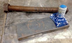
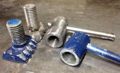
I rounded up up some donor material, some flat bar and some 5/8” all thread (with nut welded on the end).

attachment.php


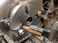
I cut the bar stock to size and drilled the 21/64” hole? required to thread it which would be used to secure the piece to the face plate of the lathe for machining the tapers on each side of the piece of flat bar. My 10” lathe was just big enough to cut the radius on and you can see where the nut holding it to the face plate had to be cut into on the inside when cutting the inner radius. I wanted to use a through bolt to fasten the piece to the face plate whereas when I did the Record ones I think I tapped the threads and just bolted into the threads from the face plate so I had nothing sticking up near my lathe bit like this nut was.

attachment.php


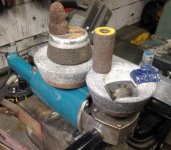
As it was I was unable to cut the radius at the last area near the nut. I was afraid to thread it because I could see that would compromise the amount of solid steel on the toothed side. Should I just use a half round file to finish I wondered then I remembered those radiused grinding wheels I’d been picking up at the swap meet (Knowing deep inside I would need them one day). These things were perfect to finish the inside radius to match the original. I clamped the angle grinder in the vise and was good to go. It’s not the 1st time one of these has bailed me out and they’re cheap at the swap meet.

attachment.php


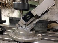
It was time to grind the teeth into the outer radius but wait... maybe I can do that on my new mill drill!

attachment.php


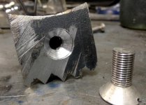
Humm... by this point I realized I should have started at the middle tooth because after figuring the vise angle and the tilt of the work in the vise my middle tooth was off center a bit. “Of Coarse” I realized the teeth are actually on a radius and I’m machining straight steps! I should have started in the middle and changed the angle on the vise for each tooth after that. I decided to surge ahead and just cut the 1, 2 and 4 +5 tooth deeper into the piece then figure the slight angle changes later (with a file).

attachment.php


The other lack of vision I had which became obvious was threads have a crest and a valley (root) whereas I’d been cutting square corners with my end mill. The only end mill I had with adequate corner bevel was rather large so I decided I just wouldn’t cut right into the corners. The other thing that was becoming obvious was when cutting gear teeth on an angled radius like this is the actual thread pitch changes from the outside to the inside where it’s a shorter distance. Fortunately the roots and crests on the original are very large so I still had room to correct things. I used a cutoff blade in a die grinder to trim valleys from my scribe lines between top and bottom and finished off with a file. Laying my lug on to of the original they are very close but it will be a while before I cut any helical teeth on anything with my new mill drill.

attachment.php


attachment.php
 

Attachments

  • ReedSwivelSm_5900.jpg
    ReedSwivelSm_5900.jpg
    61 KB · Views: 355
  • ReedSwivelSm_5865.jpg
    ReedSwivelSm_5865.jpg
    47.5 KB · Views: 363
  • ReedSwivelSm_5874.jpg
    ReedSwivelSm_5874.jpg
    62.1 KB · Views: 353
  • ReedSwivelReedSm_5870.jpg
    ReedSwivelReedSm_5870.jpg
    62.9 KB · Views: 359
  • ReedSwivelSm_5876.jpg
    ReedSwivelSm_5876.jpg
    48.4 KB · Views: 355
  • ReedSwivelSm_5880.jpg
    ReedSwivelSm_5880.jpg
    56.4 KB · Views: 357
  • ReedSwivelSm_5910.jpg
    ReedSwivelSm_5910.jpg
    54 KB · Views: 360

2oolhound

Well-known member
Joined
Dec 18, 2010
Messages
5,918
Location
BC Canada
I was glad I hadn’t cut threads into the piece yet as it definitely would have weakened it. I decided to make a new stud instead of using the all thread. I’d turn a friction fit round rod for the hole and step it up to cut the threads for the top section.

attachment.php


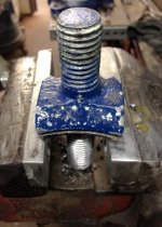
I got to admit at this point I pondered trash canning the whole thing but then thought no, I’ll drill and tap the bottom of the stud and secure the toothed lug to the stud with a set screw. That way if I want to cut a new lug with new teeth I’ll only need to make that one part.

attachment.php


I stuck it together with lock tight.

attachment.php


Well I got cold feet about the lock tight thinking if it ever came loose I’d have unbolt the vise and deal with it so I tacked 2 welds on the sides of the stud to the lug. I made mine 1/8” longer than the stock one but it’s all in place and working well.

attachment.php


Don't anybody tell me how cheap I could have bought these new parts for from Reed. :)
 

Attachments

  • ReedSwivelSm_5899.jpg
    ReedSwivelSm_5899.jpg
    49 KB · Views: 356
  • ReedSwivelSm_5884.jpg
    ReedSwivelSm_5884.jpg
    53.3 KB · Views: 356
  • ReedSwivelSm_5917.jpg
    ReedSwivelSm_5917.jpg
    53.7 KB · Views: 364
  • ReedSwivelSm_5895.jpg
    ReedSwivelSm_5895.jpg
    52.1 KB · Views: 360

Shiftless

Well-known member
Joined
Mar 9, 2014
Messages
14,580
Location
East Bay SFO
Thanks for posting that very detailed description of how you accomplished your upgrade. Great pics!

Sure, you could have bought the part from Reed, but where’s the fun in that?
 

2oolhound

Well-known member
Joined
Dec 18, 2010
Messages
5,918
Location
BC Canada
Sure, you could have bought the part from Reed, but where’s the fun in that?

Thanks Shiftless. I'm always torn on how much detail to include and how many photos. I know many folks access off cell phones and don't like too many photos. I'm still old school, use a computer and like big photos. Photos can include details you don't even think to mention.

My shop class back in the 60's had no welder, no lathe, no mill, it was pretty bare bones so now I have some of these tools (at the low quality level) I feel like a kid in shop class. It must be boring to the talented pros but there's all kinds here and these sites rely on contributions. We all need to step up to the plate sometimes.

AND Yeah, it's all about spending the time and doing it! :thumbup:
 
OP
D

drivesitfar

Well-known member
Joined
Oct 23, 2013
Messages
36,062
Location
Pacific Northwest
2ool: i'm another member that appreciates all the pictures and the details another member posts about a repair they made without buying that particular part. sure you might have been able to buy it, but next time you find you need something UNOBTANIUM you can reach into your bag of skills and maybe make it yourself.

good call on the welding tacking cause yep the loctite might not have held up vs. a rusted bolt if that happened later and then a lot of work to get it apart then would be a lot harder.

WELL DONE!!
 

javie

Active member
Joined
Sep 15, 2019
Messages
37
Location
Missouri
JAVIE: your Athol looks great to me, but you had thoughts of making it as shiny as possible. is that still the goal?

Levi: cool badge. sorry I'm not the one to ask about removing badges and attaching them, but many members enjoy doing that so maybe one of them will show up to answer your questions.
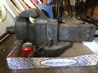
I'm thinking I like it like this too. Those hammer marks and scratches just add character. I'll probably use a bit of black paint on the lettering and then seal it with Rustoleum High Performance Clearcoat with Johnson's wax on the machined surfaces.
 

Shiftless

Well-known member
Joined
Mar 9, 2014
Messages
14,580
Location
East Bay SFO
Here is a shot of my latest project that I just finished last night. It’s a Reed 103 1/2 dated 10 35

It was pretty bad when I started. Grayish black paint with a good dose of surface rust and more than a few dings and marks from stray hacksaws and/or cut off wheels. Sorry, I didn’t take a “before” picture. :(

I used Modern Masters satin metallic paint. The color is Oxford Brown. It’s a very dark brown. Really more of a black with some brown in it. 2 coats on the sides directly over iron that was stripped using the Simple Green soak. The jaw towers got Rustoleum self etching sandable primer and then 3 coats of the MM satin metallic. No clear coat.
After cleaning up the handle and meatball with sandpaper, a wire wheel and finally a Scotchbrite flap wheel, I rubbed on some Fluid Film to preserve the finish.
The slide had a lot of rust and uneven staining. I attacked that with a knotted wire wheel on my angle grinder. Then I sprayed on a bit of Fluid Film and rubbed it off with a paper towel (which will be removing black oily residue). Then repeat. Then repeat again. This gives you control on the degree of blackness you want to end up with on the steel. Personally, I’d never want a polished slide on an 85 year old vise.
 

Attachments

  • F78481F8-2253-405C-80A7-5435D015AB29.jpg
    F78481F8-2253-405C-80A7-5435D015AB29.jpg
    136.4 KB · Views: 64
  • 5D8B71EC-48EB-4AE7-9B2F-52B5B3539F61.jpg
    5D8B71EC-48EB-4AE7-9B2F-52B5B3539F61.jpg
    70.5 KB · Views: 53
Last edited:

2oolhound

Well-known member
Joined
Dec 18, 2010
Messages
5,918
Location
BC Canada
That's beautiful. I like the brown tint.

I've never used fluid film but it looks like it adds color. I'm working on a table saw that the motor slides back and forth over a 12" steel shaft when tilting the blade. There is very little clearance between the 3" long spacer the motor bolts to and the shaft. I don't want the shaft to rust. I'm wondering if fluid film would be a good finish for the shaft and spacer.
 

robelichr

Member
Joined
Apr 21, 2020
Messages
17
Location
Long Island, NY
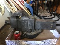
IMG_0121.jpg I bought this vise a few days ago and when I got it to the garage it was night time and I had to take it apart so I could get it out of the trunk. I got it to the garage and put it back together and snapped a picture. As I was looking at the picture today I noticed that somebody at some point may have added a swivel to this Morgan Chicago 6" vise. I'm not a vise expert, so any input would be appreciated, thanks in advance.
 

Mslund1

Well-known member
Joined
Feb 9, 2019
Messages
133
Location
Michigan
IMG_0121.jpg I bought this vise a few days ago and when I got it to the garage it was night time and I had to take it apart so I could get it out of the trunk. I got it to the garage and put it back together and snapped a picture. As I was looking at the picture today I noticed that somebody at some point may have added a swivel to this Morgan Chicago 6" vise. I'm not a vise expert, so any input would be appreciated, thanks in advance.


Nope, that looks like a factory swivel base to me.

They’re made for either style, solid mount or swivel.

Awesome vise, I have its older cousin the 160

beba87b8396dae97756166bad0f2ed7b.jpg


Sent from my iPhone using Tapatalk Pro
 

Attachments

  • beba87b8396dae97756166bad0f2ed7b.jpg
    beba87b8396dae97756166bad0f2ed7b.jpg
    248.3 KB · Views: 2

Shiftless

Well-known member
Joined
Mar 9, 2014
Messages
14,580
Location
East Bay SFO
Thanks 2oolhound
Yes, that sounds like an excellent application for Fluid Film. I have an aerosol can of the stuff so it’s easy to just squirt it on something and smear it around with my fingers.
 

robelichr

Member
Joined
Apr 21, 2020
Messages
17
Location
Long Island, NY
Nope, that looks like a factory swivel base to me.

They’re made for either style, solid mount or swivel.

Awesome vise, I have its older cousin the 160

beba87b8396dae97756166bad0f2ed7b.jpg


Sent from my iPhone using Tapatalk Pro
Thanks Mslund1, the reason I was confused was the part of the base under the dynamic jaw. All the swivel vises that I have seen where the stationary jaw sits on the swivel they are symmetrical. This vise the stationary jaw that meets the swivel is oval shaped and has what looks like a mounting hole. Did any other vise manufactures do this?
 

Attachments

  • beba87b8396dae97756166bad0f2ed7b.jpg
    beba87b8396dae97756166bad0f2ed7b.jpg
    248.3 KB · Views: 2

robelichr

Member
Joined
Apr 21, 2020
Messages
17
Location
Long Island, NY
Thanks again to all of you. Most of the vises I've come across have not been as big as this vise. All the smaller vises I've seen had a round base and a round swivel. I guess that when you get to the larger size vises that there are more options.
 

2oolhound

Well-known member
Joined
Dec 18, 2010
Messages
5,918
Location
BC Canada
That 3rd hole is used for mounting without the swivel as it's under the slide where you can't use a lock down nut like you do on the sides. Many vises are like that.
 

Halbert

Member
Joined
Apr 19, 2020
Messages
13
Location
PA
the above lewis no 10 vise. Here are. edit and after pictures.

Right after evaporust.
fc10bb7fdd40605bfc497167ef77c746.jpg

After one coat of black metal oil.
c1cc7cbe0af83857403431bfd76940f3.jpg

after the second coat of black metal oil. I tried my best to file/sand off any finish on the lettering after I let this dry for a few days.
9332c8cd5387d498bfc0f9614fc3f086.jpg

I let it dry for about 5 days and then sprayed 2 coats if clear guard clear coat.

this is after it dried.
28132495304372e8bdb6875579219891.jpg
37d48d1b8ba98bc25756999422c8e28c.jpg
5725f3ed634b78a295b41a3b8d0e43cd.jpg

This looks fantastic. I'd never heard of black metal oil. Is it similar to applying bluing?
 

Attachments

  • 37d48d1b8ba98bc25756999422c8e28c.jpg
    37d48d1b8ba98bc25756999422c8e28c.jpg
    142.7 KB · Views: 2
  • 28132495304372e8bdb6875579219891.jpg
    28132495304372e8bdb6875579219891.jpg
    132.1 KB · Views: 2
  • 9332c8cd5387d498bfc0f9614fc3f086.jpg
    9332c8cd5387d498bfc0f9614fc3f086.jpg
    125.9 KB · Views: 2
  • c1cc7cbe0af83857403431bfd76940f3.jpg
    c1cc7cbe0af83857403431bfd76940f3.jpg
    108.6 KB · Views: 3
  • fc10bb7fdd40605bfc497167ef77c746.jpg
    fc10bb7fdd40605bfc497167ef77c746.jpg
    95.1 KB · Views: 3
  • 5725f3ed634b78a295b41a3b8d0e43cd.jpg
    5725f3ed634b78a295b41a3b8d0e43cd.jpg
    109.1 KB · Views: 1
To avoid these ads, REGISTER NOW!
Top Bottom