To avoid these ads, REGISTER NOW!

Above 1200 Sq/FT The Lone Beech Garage (60x46x16)

Wokspaces above 1200 squarefeet.
OP
S

sbosecker

Well-known member
Joined
Sep 25, 2012
Messages
3,539
Location
Peachtree City, GA
Friday - October 16, 2020

I know I spend too much time on eBay & Craigslist. I don't have a problem - I can quit whenever I want to.

Anyway...

I had been watching what was was advertised as a Lista Cabinet for over a month. It looked a bit beat up but the price seemed fair and, at current gas prices, it wasn't too far away - about 75 miles.

Yesterday I realized I could actually use this cabinet. I need to get more organized in the metal/auto shop areas of the LBG. I was pretty sure this cabinet would fit between the JET Mill and the Rockwell Lathe and could serve as storage cabinet for tooling.

Even though I thought the advertised price was fair, I knew the item had been for sale for quite a while. I sent the seller a query asking if there was any flexibility in the price. After a bit I received a response with a 22% reduction in price.

A half hour later I was on my way to Wadley Alabama. It was a pleasant fall afternoon and I was enjoying traveling through rural Georgia & Alabama. After about 40 minutes of driving I was in country I had never seen before and it's almost always a pleasure to see new things.


20201015-01.jpg 20201015-02.jpg

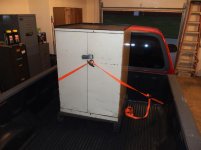
Four hours later I was back home with my prize. The rack in the bottom of the cabinet holds NMTB 30 tooling - which I don't have. This rack can be removed easily.
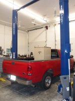

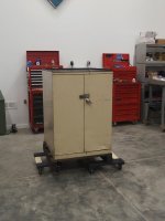

20201016-03.jpg 20201016-04.jpg 20201016-05.jpg

This afternoon I unloaded the cabinet. In its previous life it had been hit low in the front leaving some pretty good dents. The damage was worse on the right side.
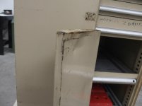


20201016-06.jpg

I removed the right door and turned it upside down.
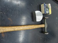


20201016-07.jpg

I got out a hammer and dolly.


Continued in next post...
 
Last edited:
To avoid these ads, REGISTER NOW!
OP
S

sbosecker

Well-known member
Joined
Sep 25, 2012
Messages
3,539
Location
Peachtree City, GA
Continued...


20201016-11.jpg 20201016-12.jpg

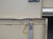
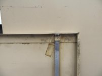
While the bottom was very rough, the top had issues as well. Before & after of the top edge of the right door. A lot more whacking was done on the lower front face to iron it out.


20201016-13.jpg

The left door got similar treatment and, while it doesn't look like new, it looks much better.

I removed the hasp and worked a bit on the latching mechanism. The doors now operate well. The drawers are filthy but roll smoothly.

Although perfectly functional as is, I think a thorough cleaning and some paint would do wonders for the cabinet.

Scott
 
Last edited:

shortykorte

Well-known member
Joined
Sep 1, 2014
Messages
8,039
Location
Tallahassee, Fl
Great score. That looks perfect for between the lathe and mill. The pullout shelves are going to be great for big things like vises, angle plates and lathe chucks.


Sent from my iPhone using Garage Journal
 
OP
S

sbosecker

Well-known member
Joined
Sep 25, 2012
Messages
3,539
Location
Peachtree City, GA
Sunday - October 18, 2020


20201018-01.jpg

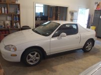
Last Thursday evening, when I acquired the Lista Cabinet, I just left it in the bed of the pickup and parked it in the house garage for the evening. So the next morning I used my wife's 1997 Honda del Sol to get to a doctor's appointment. As I drove the car on Friday morning I tried to engage the Cruise Control but it didn't engage.


20201018-02.jpg

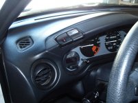
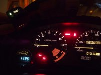
The Cruise Control's Main Switch is located on the left side of the dashboard. When the switch is pushed down, the Cruise Control is armed and the "CRUISE" light in the switch should illuminate. None of that happened on Friday morning.

Note: The red light in the "dummy switch" next to the Cruise Control's Main Switch was part of a Alarm System installed by the previous owner.

I asked my wife if she had noticed the Cruise Control wasn't working and she stated she was not aware of this. She normally doesn't use the Cruise Control for her short 10 minute drive to work.


20201018-03.jpg

First Cruise Control component to check is the Cruise Control's Main Switch.

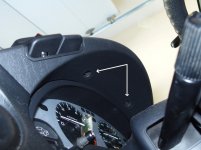
The section of the Dashboard that contains the Main Switch is held in place by 2 screws under the lip of the Dashboard. After these two screws are out only some clips along the top of this section of the Dashboard keep it in place.


20201018-04.jpg 20201018-05.jpg 20201018-06.jpg

A bit of pulling on the Dashboard and it comes away from the Instrument Panel. At this point the wiring for 3 switches are all that tie the Dashboard to the Instrument Panel.


20201018-07.jpg

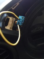
The switches are unplugged from their wires and the Dashboard is free.


Continued in next post...

KEYWORDS: 1997 del Sol Cruise Control
 
Last edited:
OP
S

sbosecker

Well-known member
Joined
Sep 25, 2012
Messages
3,539
Location
Peachtree City, GA
Continued...


20201018-11.jpg 20201018-12.jpg

The Dashboard is now free. The Blue switch is the Cruise Control Switch. The Cruise Control Switch & the Dummy Switch are held in a bezel that is held in place with a metal (a little rusty) clip on both sides of the bezel.


20201018-13.jpg 20201018-14.jpg

Squeezing those metal clips allows the bezel to be pulled free of the Dashboard.


20201018-15.jpg 20201018-16.jpg 20201018-17.jpg

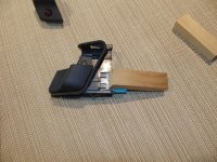
The individual switches have 4 plastic clips - 2 on the top & 2 on the bottom - that have to be depressed at the same time to remove the switch from the bezel. I found it impossible to squeeze them all down with my fingers at the same time and be able to put any force on the switch to move it.

I used a couple pieces of scrap wood to pinch the plastic clips down - this allowed me to remove the switches from the bezel.


Continued in the next post...

KEYWORDS: 1997 del Sol Cruise Control
 
Last edited:
OP
S

sbosecker

Well-known member
Joined
Sep 25, 2012
Messages
3,539
Location
Peachtree City, GA
Continued...


20201018-21.jpg

My Shop Manual had indicated the sequence of Cruise Control components to be tested to troubleshoot this system.


20201018-22.jpg 20201018-23.jpg

As mentioned previously, the Main Cruise Control Switch was first on the list.


20201018-24.jpg

The testing consisted of checking continuity between pins on the Cruise Control Switch - both with the switch in the On and also in the Off position.

I did all the tests and got continuity in all the tests except for the test between the A pin and the B pin. I wouldn't think this would keep the Cruise Control from working but the manual says if any continuity test fails one should replace the switch.

These switches are not available from Honda any more. Now to try to find a switch from either eBay or a junk yard.

Scott

KEYWORDS: 1997 del Sol Cruise Control
 
Last edited:

Matt Johnson

Well-known member
Joined
May 2, 2014
Messages
59
Location
Washington State
20201018-23.jpg

I did all the tests and got continuity in all the tests except for the test between the A pin and the B pin. I wouldn't think this would keep the Cruise Control from working but the manual says if any continuity test fails one should replace the switch.

First let me say that it's been 20 years since I've worked on that generation of Honda's electrical system, but in all honesty is one of the most straight forward produced (little computer/control module or other bs for simple systems).

Based on the diagram above the Pinouts should be -
A = Ground for "Active" indicator lamp
B = Switch Output when "Active"
C = Unclear, either Power or Ground for Lamp likely from dash dimmer circuit
D = Opposite Power or Ground to complete circuit with Pin C
E = Switch Input

I would have to agree with you, Pin A to Pin B should only allow power to complete the circuit & illuminate the bulb when the switch is "activated"/closed from Pin E.

It's great & handy that you have the factory Honda DelSol manual.
Though you indicated this outlined the first step of the diagnosis process was to check continuity at the switch, did you happen to first check any fuse location?

The following may or may not be outlined in the manual.
You should be able to insert a jumper into the dash wiring harness pin housing (with the switch removed) connecting Pin E to Pin B.
This would effectively close/bypass the switch feature of the system.
Then test drive & use the steering wheel controls (IIRC the vehicle has to be 30+ MPH, or there about, to allow cruise to take over).

Another thing I personally would do, after seeing the corrosion on the metal retaining clips & with the knowledge that you wife doesn't routinely activate the switch.
It maybe possible that the switch contacts are simply corroded or have some slight film on them.
I'd take the switch apart, check & clean as needed.
Note - there will likely be at least 1 spring in the assembly, so take precaution to keep all parts in close order for ease of reassembly.

I hope that helps & I wish you well!

Matt
 
OP
S

sbosecker

Well-known member
Joined
Sep 25, 2012
Messages
3,539
Location
Peachtree City, GA
First let me say that it's been 20 years since I've worked on that generation of Honda's electrical system, but in all honesty is one of the most straight forward produced (little computer/control module or other bs for simple systems).

Based on the diagram above the Pinouts should be -
A = Ground for "Active" indicator lamp
B = Switch Output when "Active"
C = Unclear, either Power or Ground for Lamp likely from dash dimmer circuit
D = Opposite Power or Ground to complete circuit with Pin C
E = Switch Input

I would have to agree with you, Pin A to Pin B should only allow power to complete the circuit & illuminate the bulb when the switch is "activated"/closed from Pin E.

It's great & handy that you have the factory Honda DelSol manual.
Though you indicated this outlined the first step of the diagnosis process was to check continuity at the switch, did you happen to first check any fuse location?

The following may or may not be outlined in the manual.
You should be able to insert a jumper into the dash wiring harness pin housing (with the switch removed) connecting Pin E to Pin B.
This would effectively close/bypass the switch feature of the system.
Then test drive & use the steering wheel controls (IIRC the vehicle has to be 30+ MPH, or there about, to allow cruise to take over).

Another thing I personally would do, after seeing the corrosion on the metal retaining clips & with the knowledge that you wife doesn't routinely activate the switch.
It maybe possible that the switch contacts are simply corroded or have some slight film on them.
I'd take the switch apart, check & clean as needed.
Note - there will likely be at least 1 spring in the assembly, so take precaution to keep all parts in close order for ease of reassembly.

I hope that helps & I wish you well!

Matt

Matt,

Thank you for that very thoughtful post.

I did check the under the dash fuses mentioned in the Troubleshooting Chart. I also looked in the Shop Manual at the function of the 3 mentioned Under-Hood fuses and their functions seemed to preclude that they had failed as all the systems associated with them were functional.

The corrosion on the clips wasn't as bad as it looked in the pictures and, many years ago, I had asked my wife just to keep the Main Cruise Control Switch engaged at all times. This technique allowed the Cruise Control to always be armed and the operator's hand wouldn't have to reach up on the dash to start the sequence of using the Cruise Control. I don't know if I could take the switch apart without breaking it but while on the subject of switch anatomy...


20201020-01.jpg

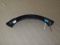
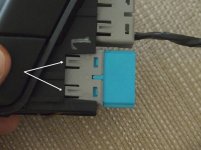
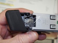
It looks like there may be access to the 2 light bulbs inside the switch (white arrows) - any knowledge on replacing those?

The black arrows point to a couple of clips (another pair on opposite side)...
are those clips the key to getting the switch apart?

I really like your technique of jumping the B & E receptacles of the Wiring Harness's Female connector to effectively "close" the Main Cruise Control's switch. That should either find the main switch guilty or exonerate it.

A late search (on my part) of the Internet found many people fixing this issue with an adjustment of the clutch switch or replacement of the "pedal pad". Those two fixes often cured their Cruise Control problems. The Shop Manual's troubleshooting chart has the clutch switch only being checked for a failure of the Cruise Control to disengage when the clutch is depressed. It would be easy enough to check that with the Main Switch reinstalled.

That's on my short list. HA!

Thank you again for the benefit of your experience.

Best regards,

Scott
 
Last edited:

gilr

Well-known member
Joined
Jul 26, 2008
Messages
300
Location
Richmond, VA
Hi Scott, I recall you replaced the pedal pad on the Del Sol recently and I'm sure if the break switch is activated it prevents the Cruise Control from activating or will de-activate it when in Cruise mode. So will the clutch switch. I'd check the adjustment of the break switch first to see if that is why the Cruise doesn't activate. There is an adjustment procedure in the manual, I'm sure. and I'd start there. My daughter's Odyssey minivan had a similar problem and it was the adjustment of the brake switch.

Gil
 

Matt Johnson

Well-known member
Joined
May 2, 2014
Messages
59
Location
Washington State
...I don't know if I could take the switch apart without breaking it but while on the subject of switch anatomy...
...

It looks like there may be access to the 2 light bulbs inside the switch (white arrows) - any knowledge on replacing those?

The black arrows point to a couple of clips (another pair on opposite side)...
are those clips the key to getting the switch apart?

I really like your technique of jumping the B & E receptacles of the Wiring Harness's Female connector to effectively "close" the Main Cruise Control's switch. That should either find the main switch guilty or exonerate it.

A late search (on my part) of the Internet found many people fixing this issue with an adjustment of the clutch switch or replacement of the "stop pad". Those two fixes often cured their Cruise Control problems. The Shop Manual's troubleshooting chart has the clutch switch only being checked for a failure of the Cruise Control to disengage when the clutch is depressed. It would be easy enough to check that with the Main Switch reinstalled.

I'm happy to help & offer assistance when I feel my insight might be beneficial.
Again, on this specific topic, it's been along time & in all honesty I'm much more experienced in VW/Audi brand systems. So take my input as food for thought rather than being from a subject expert. (my disclaimer, hahaha)

I had honestly forgot about the bulbs (your White Arrows) being removable/replaceable, as most newer vehicles for this type of switch that's not an option & require purchasing a complete unit (typically when they transitioned to LED but not always).
You can insert a flat tip screw driver into the slot of each bulb & turn 1/8 to 1/4 to unlock & remove (sometimes they will unlock but not release, you have to turn upside down & give a good tap to dislodge).
Once you have the bulb/s out you can see the contacts & check continuity using your meter.

The Black Arrows you noted look to be the correct ones for starting the switch disassembly process.
Of which the bulbs have to be removed (IIRC) to allow the switch to slide apart.
Typically the Tabs @ Black Arrows involve inserting a small flat tip or similar to "gently lift" the grey part of the housing over the blue part's tabs.

With the Switch Bypass by Jumping, if you'd like you can always put a Low Amp Fuse inline on your jumper wire to protect the circuit.
But I think with where you're at in the process currently, I'd throw a jumper in it & drive.

I also agree with your & Gil's logic of the clutch & brake switches being areas of potential diagnosis, though without seeing a schematic/wiring diagram I'm not sure when they specifically influence the circuit.
So leads back to "jump it" on the dash harness pin housing & check the function of the brake & clutch switches when driving.
As you indicated, I think that these 2 just tell the cruise control module to disengage & only come into play after the Vehicle Speed Sender output has said "yep we've hit 30 MPH" (may actually be 27mph the more I think about it).

I'm happy to offer some advice & hope that helps!

Matt
 
OP
S

sbosecker

Well-known member
Joined
Sep 25, 2012
Messages
3,539
Location
Peachtree City, GA
Hi Scott, I recall you replaced the pedal pad on the Del Sol recently and I'm sure if the break switch is activated it prevents the Cruise Control from activating or will de-activate it when in Cruise mode. So will the clutch switch. I'd check the adjustment of the break switch first to see if that is why the Cruise doesn't activate. There is an adjustment procedure in the manual, I'm sure. and I'd start there. My daughter's Odyssey minivan had a similar problem and it was the adjustment of the brake switch.

Gil


Gil,

Thanks for your thoughts!

It wasn't lost on me that I had been putzing around under the dash working on the Brake Switch Pedal Pad just before I noticed the Cruise Control wasn't working.

That was one of the reasons I queried my bride if she had noticed the Cruise Control wasn't working. I was hoping for either "Yeah, it just stopped working" or "Oh yeah, I meant to tell you that it hasn't worked for some time" but she was unable to provide either of those since she doesn't engage the Cruise Control that often.

I'd ruled out the Brake Switch since my repair had fixed the "Brake Lights Are Always On" problem. The logic being:

1. There's just one Brake Switch
2. It's a binary on/off situation
3. The Brake Lights now work properly so the switch is working properly.

Perhaps that's flawed in some way but that's what I was thinking.

I don't know what else the Clutch Switch controls (if anything) so I'm more inclined to give it the stink eye first. I'll be getting deeper into this in the near future.

Thanks again for posting your suggestions!

Best regards,

Scott
 
OP
S

sbosecker

Well-known member
Joined
Sep 25, 2012
Messages
3,539
Location
Peachtree City, GA
I'm happy to help & offer assistance when I feel my insight might be beneficial.
Again, on this specific topic, it's been along time & in all honesty I'm much more experienced in VW/Audi brand systems. So take my input as food for thought rather than being from a subject expert. (my disclaimer, hahaha)

I had honestly forgot about the bulbs (your White Arrows) being removable/replaceable, as most newer vehicles for this type of switch that's not an option & require purchasing a complete unit (typically when they transitioned to LED but not always).
You can insert a flat tip screw driver into the slot of each bulb & turn 1/8 to 1/4 to unlock & remove (sometimes they will unlock but not release, you have to turn upside down & give a good tap to dislodge).
Once you have the bulb/s out you can see the contacts & check continuity using your meter.

The Black Arrows you noted look to be the correct ones for starting the switch disassembly process.
Of which the bulbs have to be removed (IIRC) to allow the switch to slide apart.
Typically the Tabs @ Black Arrows involve inserting a small flat tip or similar to "gently lift" the grey part of the housing over the blue part's tabs.

With the Switch Bypass by Jumping, if you'd like you can always put a Low Amp Fuse inline on your jumper wire to protect the circuit.
But I think with where you're at in the process currently, I'd throw a jumper in it & drive.

I also agree with your & Gil's logic of the clutch & brake switches being areas of potential diagnosis, though without seeing a schematic/wiring diagram I'm not sure when they specifically influence the circuit.
So leads back to "jump it" on the dash harness pin housing & check the function of the brake & clutch switches when driving.
As you indicated, I think that these 2 just tell the cruise control module to disengage & only come into play after the Vehicle Speed Sender output has said "yep we've hit 30 MPH" (may actually be 27mph the more I think about it).

I'm happy to offer some advice & hope that helps!

Matt


Matt,

Again - Thanks for the benefit of your experience!

I'll be returning to the del Sol repair soon but today I decided to try to fix the F150's Temperature/Compass display.

I'm getting tired of most of my ancient vehicles having wires hanging out everywhere and looking like a Hydra.

Best regards,

Scott
 

gilr

Well-known member
Joined
Jul 26, 2008
Messages
300
Location
Richmond, VA
Hi Scott,

There is a separate set of contacts in the break switch for the cruise control that may have failed, your manual should show the diagram for this. The break switch can be adjusted for depth to allow the break lights to light and to interrupt the cruise control, so it is possible to be that. The clutch switch will also shut down the cruise to prevent the cruise control from over revving the engine when the clutch is depressed. Either of these can interfere with the cruise control operation and prevent it from engaging if one of these contracts are defective. I would certainly try to jump the contact to enable the cruise first as Matt suggested before condemning the other possibilities. Let us know what you find.

Gil
 
OP
S

sbosecker

Well-known member
Joined
Sep 25, 2012
Messages
3,539
Location
Peachtree City, GA
Tuesday - October 20, 2020


Today I took a trip to a local salvage yard: LKQ Pick Your Part in Fayetteville, GA. I knew there was a salvage yard in that location but the format has changed since the last time I had visited. They were VERY organized with an online inventory of vehicles on their lot. The inventory included pictures and location.

Very nice!

I arrived with downloaded information on the location of several F150 pickup trucks (years 1999-2003) and one 1995 Honda del Sol. I walked into the main office and for $2 I was given a hunting permit. They checked out the tool bag I had brought (4 screw drivers - Phillips/Flat/T-10 Torx), gave me a quick brief on how to find the vehicle I was looking for and then off I went.

Of the roughly dozen F150's I looked at, most had already had the Temperature/Compass Display removed or the truck didn't have one to begin with.


20201020-11.jpg

However, two pickups did have the display and one of them was a 2000 (like mine) so I quickly removed that one and put it in my bag.


20201020-12.jpg

The del Sol had the Cruise Control Switch I was interested in. I considered waiting until I had determined if my car's switch was truly faulty but then decided to grab it while I was there.

All of this took about 20 to 30 minutes and I returned to the Office with my two parts. The gal who checked me out informed me that the del Sol had just come to the lot that day. I got the impression that she thought the parts from it would go quickly.

She checked her price sheet and charged me $15 for what I had brought to the counter.


20201020-13.jpg

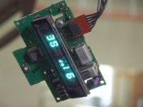
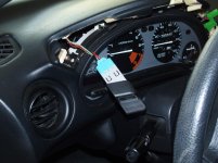
When I got home I plugged the Temperature/Compass Display into my truck's dangling cable. I turned on the truck and the instrument panel lit up but the dangling display stayed dark (arrow). A small disappointment but not much of a surprise.


20201020-14.jpg 20201020-15.jpg

Indeed, when I took the salvage yard display apart, I found the same solder joint problem as previous. Not quite as obvious when looking at it as my previous experience but when I touched the resistor it broke completely free.

I soldered the resistor and checked the others. They seemed fine. Time to check out the repair.


20201020-16.jpg

Cool.


20201020-17.jpg

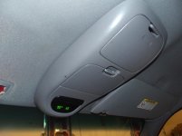
I removed the display from the truck and CAREFULLY carried it to a workbench. The display was mounted in the overhead trim and then the trim was re-attached to the ceiling of the truck.

One less Hydra in my fleet. HA!

Scott

KEYWORDS: 2000 F150 F-150 Temperature Display
 
Last edited:
OP
S

sbosecker

Well-known member
Joined
Sep 25, 2012
Messages
3,539
Location
Peachtree City, GA
Hi Scott,

There is a separate set of contacts in the break switch for the cruise control that may have failed, your manual should show the diagram for this. The break switch can be adjusted for depth to allow the break lights to light and to interrupt the cruise control, so it is possible to be that. The clutch switch will also shut down the cruise to prevent the cruise control from over revving the engine when the clutch is depressed. Either of these can interfere with the cruise control operation and prevent it from engaging if one of these contracts are defective. I would certainly try to jump the contact to enable the cruise first as Matt suggested before condemning the other possibilities. Let us know what you find.

Gil

Gil,

Thank you very much!!! Who'd a thunk it.

That's certainly worth pursuing as when I was trying to get the aftermarket Pedal Pad installed it wouldn't fit without modification.

Before said modification, I was really pushing on the Pedal Pad and I deformed the Pedal Pad housing on the Brake Pedal. The deformation was great enough that when I finally got the modified Pedal Pad in place, the brake lights remained on.

I bent the Pedal Pad Housing back enough to keep the brake lights off but - maybe - it needs more. There was still a slight bend in the housing when I got the brake lights to stay off but I figured it was good enough since the lights were off.

I'm moving my stink eye from the clutch pedal to the brake pedal. This may be the issue!

Best regards,

Scott
 
Last edited:
OP
S

sbosecker

Well-known member
Joined
Sep 25, 2012
Messages
3,539
Location
Peachtree City, GA
Thursday - October 22, 2020

Yesterday was a busy day of "life stuff" and today was better but still had plenty of that sort of thing to deal with.

The good news was that by mid to late afternoon today I had time to do a little troubleshooting on the del Sol's Cruise Control System.

The first thing to check was to use a jumper wire to connect the B & E terminals in the Dashboard Receptacle.


20201022-01.jpg 20201022-02.jpg

I used a jumper wire that I would normally use on an electronic breadboard to connect the B & E terminals in the Receptacle.

With the jumper wire in position, I took the del Sol for a test drive. I wasn't too disappointed when I attempted to engage the Cruise Control and nothing happened. Based on the troubleshooting that had been done on the switch earlier, the switch's on/off function seemed to be working fine.


20201022-03.jpg

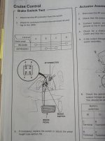
I had looked at the Cruise Control Brake Switch Test in my Shop Manual. While it was a 4 pin connector, it appeared that the test was a binary on/off test ...and since the brake light repair had worked I didn't have a lot of hope that the Brake Switch was the problem. Not to mention that the Shop Manual doesn't even list this as a possible fix for this particular Cruise Control Symptom .


20201022-04.jpg 20201022-05.jpg
20201022-06.jpg

Still... I had just messed with it during the Brake Light repair and it wasn't going to be that hard to test Gil's thesis that this was probably the issue.

I plugged in my original Main Cruise Control Switch, wrapped a nickel in painter's tape and stuck the mummified nickel onto the Brake's Pedal Pad.

I took the del Sol on another test drive ...got her up to about 40 mph and...


20201022-07.jpg

...pressed the SET button on the Steering Wheel.

The CRUISE CONTROL light illuminated and the Cruise Control held the engaged speed.

Golly!

...so a happy ending to today's troubleshooting!

A big THANKS to Gil & Matt!

I still have to adjust the Brake Pedal Stop and, before I reinstall the Dashboard, I'd like to see if I can figure out how to replace the obviously burned out bulb in the Main Cruise Control Switch.

Scott

KEYWORDS: 1997 del Sol Cruise Control Repair
 
Last edited:

gilr

Well-known member
Joined
Jul 26, 2008
Messages
300
Location
Richmond, VA
Many times when troubleshooting, you have to go back to the last thing you touched or worked on.....

Glad you were able to get it fixed!

Gil
 
OP
S

sbosecker

Well-known member
Joined
Sep 25, 2012
Messages
3,539
Location
Peachtree City, GA
Many times when troubleshooting, you have to go back to the last thing you touched or worked on.....

Glad you were able to get it fixed!

Gil

Agreed! Like I wrote, it certainly occurred to me but I talked myself out of it... since it seemed to be working. HA!

Last night I was trying to find out if the light bulbs in the junkyard switches (Aux Lights & Main Cruise Control) I had obtained could be used in my original Main Cruise Control Switch. Neither of the light bulbs in the junkyard Cruise Control Switch seem to be working so I was trying to locate information on the Aux Light Switch.

I didn't see anything in my Shop Manual's Index that referred to the Aux Light system so I started leafing through Manual's Electrical section (100+ pages) in an attempt to find information on that system.

Turns out the Aux Light System was only installed in the 1992-1995 models and I have a 1997 so I didn't find anything in my Manual.


20201023-01.jpg

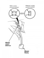
I did find this in the Brake Light section. Looks like there's different Brake Light Switch depending on whether the vehicle has Cruise Control installed.

That's what the FBI would call "a clue".

HA!

Best regards,

Scott
 
Last edited:
OP
S

sbosecker

Well-known member
Joined
Sep 25, 2012
Messages
3,539
Location
Peachtree City, GA
Saturday - October 24, 2020


With the del Sol's Cruise Control's issues diagnosed - if not completely cured - I turned my attention to the burned out bulb in the Cruise Control Main Switch.


20201023-11.jpg 20201023-12.jpg

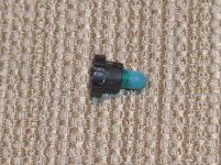
The bulbs are held in place by a base. The base is released by turning it about 30 degrees counter-clockwise, then a pair of tweezers can pull the entire bulb/base out.


20201023-13.jpg 20201023-14.jpg

This is what the bulb/base looks like. I spent quite a bit of quality Internet time tracking down information on this thing.

I did some Google Image searching for "Honda instrument bulb" and managed to find pictures of something similar to what I had in my switch. I learned they were called NeoWedge bulbs.

The only description in the shop manual for this bulb was "Indicator Light (0.84W)". I tried a variety of search terms with the .84 watt term included. Nothing was an outright "hit" but I noticed that much of what was helpfully offered by Google - particularly the Honda bulbs - were described something like "14V 80ma".

Hmmm... I think volts x amps = watts.

I divided .84 by 14 and got .06 or 60 milliamps. When I started searching for Honda NeoWedge 14V 60ma I started getting some hits that were a lot more promising.

Eventually I went down enough rabbit-holes to find a rabbit.

Here's a link to an exploded diagram of the dashboard of a 1997 del Sol.

LINK

It appears that while the Neo-Wedge Bulb that provides background illumination when the driver turns on the headlights is the same bulb for all the switches. However, there is no common Neo-Wedge bulb for the other bulb found in most of the switches. Every one of those is a different part number.

The part number for the Main Cruise Control Switch's "Indicator Light" is:

35852-SR2-901

Of course this bulb - as well as just about anything associated with that dashboard - is unobtanium from Honda. I did a Google search for that part number and didn't find any vendor selling an aftermarket bulb associated with that part number.

My only hope for an OEM bulb would seem to be eBay. I've got a saved search there for that part number.

I was hoping I could find a table of NeoWedge standards (dimensions) and I would compare the specified dimensions of the standards to my bulb. I was unable to find anything like that.

Usually I see these lamps advertise as T-1 or T-3 for what appears to be pretty much the same thing. Wedge bulbs (not NeoWedge) are listed specified as T for tubular and the number is the diameter of the lamp's tube in 1/8ths of an inch.
1/8 inch is pretty close to 3mm so maybe that's why I see T-1 & T-3 referring to bulbs that seem dimensionally similar.

Work-Arounds:

VIDEO 1

At about 9:20 this guy gives a source for LED bulbs that will supposedly work. I've ordered a white, a green & a blue one and we'll see, one, if it works and, two, which one works best for this application.

LINK2

This guy takes a 7219 Wedge Bulb and replaces the bulb in the NeoWedge with the 7219 bulb.


Scott

KEY WORDS: 1997 del Sol Cruise Control Repair Dashboard Switch Switches NeoWedge Neo-Wedge Bulb Bulbs Lamps LED 35852-SR2-901 35852SR2901 36775-SR2-A01 36775SR2A01 35851-SR2-003 35851SR2003 14V .06A 60MA
 
Last edited:
To avoid these ads, REGISTER NOW!
OP
S

sbosecker

Well-known member
Joined
Sep 25, 2012
Messages
3,539
Location
Peachtree City, GA
Sunday - October 25, 2020


Although I'm still waiting on my NeoWedge LED lamps for the del Sol's Main Cruise Control Switch, I thought I had enough time today to move the ball forward by getting Brake Switch - Pedal Pad Bracket realigned.

I removed the "mummified nickel" that had acted as a Pedal Pad extender and then I got to work trying to bend the Pedal Pad Bracket into the correct position.


20201025-01.jpg 20201025-02.jpg
20201025-03.jpg

The trick was to find some sort of "tool" that would allow me apply force to the Pedal Pad Bracket in the extremely limited space under the instrument panel.

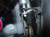
I first tried using a Starrett Machinist Vise. I placed the ends of the jaws so they were where the red arrows are. I got the Vise clamped in that position and then I pushed down on the Brake Pedal. After I did that, it appeared that Pedal Stop Bracket had moved and I thought it was probably good enough to have fixed the problem.

I took the del Sol for a test drive but found that the Cruise Control would not engage.

I brought the car back home and inserted myself, upside down, once again under the Instrument Panel. It appeared that the Pedal Pad Bracket was not completely flat against the Brake Pedal Switch. I tried positioning the Machinist Vise on the opposite side of the Pedal Pad but I just couldn't get both hands into position to achieve anything.

I decided to try a different approach. I rooted around in my scrap metal collection and found a 1/2-inch or so rod about 5 inches long. I placed one end in the vicinity of the green arrow and the other end against the floorboard. I then applied force on the Brake Pedal.

That seemed to do it. The Pedal Pad, as pictured above, was now perpendicular to the Brake Switch. Although it was a minor amount of movement compared to the position after the Vise adjustment, when I took the car for a test drive, the Cruise Control now worked properly.

Scott
 

gilr

Well-known member
Joined
Jul 26, 2008
Messages
300
Location
Richmond, VA
Scott,

I think you should be able to turn the brake switch to move it either in or out to adjust the spacing and not have to bend anything, check your manual for the procedure. I had to do that to my daughter's Odyssey to properly space the switch.

Gil
 
OP
S

sbosecker

Well-known member
Joined
Sep 25, 2012
Messages
3,539
Location
Peachtree City, GA
Scott,

I think you should be able to turn the brake switch to move it either in or out to adjust the spacing and not have to bend anything, check your manual for the procedure. I had to do that to my daughter's Odyssey to properly space the switch.

Gil


Gil,

I considered adjusting the Brake Switch but, since i perceived that the Switch's electrical connector was just about inaccessible to a normal human's hands, I abandoned that approach. As you know, the Brake Switch screws into a bracket and is locked into position with a Nut on the opposite side of the Bracket. If I needed to rotate that Brake Switch very much at all, I was going to need to unplug the electrical connector so the wires didn't twist up.

Since I had bent the Brake Pedal Pad's "Bracket Flange" as I was attempting to install the oversize aftermarket Pedal Pad, I decided to bend it back to where it was originally.

Everything associated with the Brake Switch seems to be working properly now. I'm waiting for some replacement NeoWedge lamps before I reinstall the Dashboard.

Best regards,

Scott
 
OP
S

sbosecker

Well-known member
Joined
Sep 25, 2012
Messages
3,539
Location
Peachtree City, GA
Thursday - October 29, 2020


Today my package from SuperBrightLED's arrived. Let's see if these things work in the del Sol's Cruise Control Main Switch.


20201029-01.jpg 20201029-02.jpg

I ordered a white, a blue and a green NeoWedge LED.


20201029-03.jpg 20201029-04.jpg

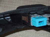
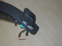
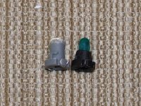
In the first picture the green LED is on the left and the original blub is on the right. This bulb lights up when the Main Cruise Control Switch is turned on and indicates the Cruise Control System is armed.

I put the green LED and the white LED into the junk yard Main Cruise Control Switch. In my first attempt neither of the LED's worked. I came back into the house, fussed a bit with the installation of the LED's and tried again.

This time the white LED worked but not the green one.

I went back to the bench and rotated the green LED 180 degrees in its mount and then returned to the del Sol.


20201029-05.jpg

Score!

I really like the look of the LEDs in broad daylight. They are a nice brightness ...and that's with the LED pointing up in the switch and not towards the front of the switch where the lettering and such are.

However I think the switch is probably too bright for use at night. It's located on the dashboard pretty much at eye level and I think it would be too aggressive. Using the "dashboard light dimmer" helps but, not surprisingly the LEDs are "out of sync" with all the rest of the incandescent lighting.

I would probably leave the LED's installed in the switch if I didn't have another option ...but I do have another option.

I've ordered a bunch of Elko 7219 T-1 Incandescent Wire Terminal Light Bulbs from Amazon. When these arrive I'm going to try replacing the existing bulb in its Neo Wedge "holder" with an Elko 7219.

We'll see how that goes.

Scott


KEY WORDS: 1997 del Sol Cruise Control Repair Dashboard Switch Switches NeoWedge Neo-Wedge Bulb Bulbs Lamps LED 35852-SR2-901 35852SR2901 36775-SR2-A01 36775SR2A01 35851-SR2-003 35851SR2003 14V .06A 60MA 7219
 
Last edited:
OP
S

sbosecker

Well-known member
Joined
Sep 25, 2012
Messages
3,539
Location
Peachtree City, GA
Friday - October 30, 2020

I attended an Estate Sale today while wearing a mask and being careful to maintain social distancing. I picked up a couple of useful things for the LBG.


20201030-01.jpg 20201030-02.jpg

The first item will help with shop safety: an Oily Rag Waste Can. I got this 10-gallon item for $15 and I was pretty happy with that. I suspect it will be getting a lot of use.


20201030-03.jpg

Then there were these pieces of steel. They're 3/4-inch thick and 6-inches wide. One is about 8-1/2 feet long and the other just a hair over 10 feet. All in all 285 pounds of steel for $54.

It's not all that unusual to find steel at the Estate Sales I attend but it is unusual to find it in this good of condition.

This sale was a target rich environment with lots of tools and other interesting things. I found most of the pricing to be strong but I was happy with the prices on the items I purchased.

A good day!

Scott
 

squirmdogg

Member
Joined
Jan 14, 2020
Messages
6
Location
Mooresville, NC
Good call on the oily rag can. Had one of those fires in my former shop while I was gone. Lid wasn’t put on a metal trash can we used. Fortunately, it was contained within the can and no damage elsewhere. Scared the bejesus out of me.


Sent from my iPad using Tapatalk
 
OP
S

sbosecker

Well-known member
Joined
Sep 25, 2012
Messages
3,539
Location
Peachtree City, GA
Good call on the oily rag can. Had one of those fires in my former shop while I was gone. Lid wasn’t put on a metal trash can we used. Fortunately, it was contained within the can and no damage elsewhere. Scared the bejesus out of me.

squirmdogg,

Spontaneous combustion can be devastating. Growing up on a farm the big concern was wet hay. It never happened when I was growing up but the old heads would talk about barns burning down due to a hay bale self-igniting.

Best regards,

Scott
 
OP
S

sbosecker

Well-known member
Joined
Sep 25, 2012
Messages
3,539
Location
Peachtree City, GA
Monday - November 2, 2020


20201102-01.jpg

The 7219 bulbs arrived in today's mail. These should be suitable replacements for one of the incandescent bulbs in the del Sol's Main Cruise Control Switch.

They are tiny things.


20201102-02.jpg 20201102-03.jpg 20201102-04.jpg

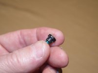
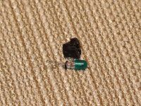
The first task was deconstructing the original NeoWedge bulb. I had to pick at the end of the wire that was wrapped around the NeoWedge base. Once both wires were free, I could pull the bulb from the base. The last step was removing the flexible, green sheath from the bulb.


20201102-05.jpg

Probably the most difficult task was putting the green sheath on the new 7219 bulb.

Did I mention these things were tiny?


20201102-06.jpg

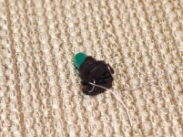
The next hardest thing was threading those fine terminal wires through the NeoWedge base. Once that was done I was in the home stretch and just needed to wrap the terminal wires around the base and trim them off.


20201102-07.jpg

I plugged the repaired switch into the del Sol's wiring and turned on the lights. The repair worked.

The green "Armed" light is a bit washed out in this picture but even the unwashed out reality is a diminished green compared to the vibrant green LED light of the previous repair attempt.

The incandescent solution does dim properly with the del Sol's other lighting when the dimmer switch is used.

I had to quit for the evening but I hope to get the Dashboard put back together tomorrow.

Scott


KEY WORDS: 1997 del Sol Cruise Control Repair Dashboard Switch Switches NeoWedge Neo-Wedge Bulb Bulbs Lamps LED 35852-SR2-901 35852SR2901 36775-SR2-A01 36775SR2A01 35851-SR2-003 35851SR2003 14V .06A 60MA 7219
 
Last edited:

Matias

Well-known member
Joined
Feb 28, 2015
Messages
616
Location
Finland
Nice work on the cruise control. A lot of investigation work and small orders, but must be satisfying to get it to work as intended.
 
OP
S

sbosecker

Well-known member
Joined
Sep 25, 2012
Messages
3,539
Location
Peachtree City, GA
Nice work on the cruise control. A lot of investigation work and small orders, but must be satisfying to get it to work as intended.

Matias,

You are exactly correct!

I get a kick out of trying to keep a car working the way it came out of the factory. I've got some older vehicles so I have many opportunities to be satisfied. HA!

I see you are from Finland. I flew into Helsinki from New York in August 1994 as a co-pilot on a Lockheed L-1011. We dropped the flight attendants off and picked up a new group that had laid over in Helsinki. We then flew on to St Petersburg Russia and stayed there for 48 hours. The flight attendants flew back to Helsinki and then on to New York. After 48 hours in Russia we pilots flew back to Helsinki and then on to New York.

So I've been to Finland (Twice!) but my total time in your country was less than 3 hours.

Best regards,

Scott
 

Matias

Well-known member
Joined
Feb 28, 2015
Messages
616
Location
Finland
Matias,
I see you are from Finland. I flew into Helsinki from New York in August 1994 as a co-pilot on a Lockheed L-1011. We dropped the flight attendants off and picked up a new group that had laid over in Helsinki. We then flew on to St Petersburg Russia and stayed there for 48 hours. The flight attendants flew back to Helsinki and then on to New York. After 48 hours in Russia we pilots flew back to Helsinki and then on to New York.

So I've been to Finland (Twice!) but my total time in your country was less than 3 hours.

Thanks Scott, I admit I had to google the L-1011 as I wasn't familiar with it. August is good, means that at least it should've been warm and not dark like now.
 
OP
S

sbosecker

Well-known member
Joined
Sep 25, 2012
Messages
3,539
Location
Peachtree City, GA
Sunday - November 15, 2020

It's been a while since I have been able to fit in some time in the shop. Last weekend my wife and I got a quick turnaround COVID test to ensure as best we could that we weren't a threat. With the test results negative for the both of us, we departed Saturday morning for the 8-hour drive to the Lone Beech Melon Farm in Knox County, IN.

On Sunday my brothers and our families celebrated my father's 90th birthday. I hadn't been home to see dad since February and I wasn't going to miss this very big birthday if at all possible.

So some good stuff has kept me out of the shop but today...

I started a little project.

I wanted a mobile base for my 8-inch Delta Wood Jointer. Yesterday I rummaged around looking at various bits of Estate Sale purchases, leftover materials from the Lone Beech Garage's construction and remnants from a very large homemade cabinet that was given to me.


20201115-01.jpg 20201115-02.jpg

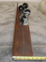
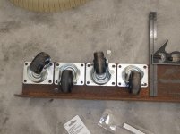
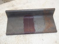
I found a piece of angle iron that had one flange that was 5-inches long. I'm pretty sure that item was purchased for small money at an Estate Sale. The Casters were from the free homemade cabinet that I got from the friend of a friend. The cabinet was VERY heavy so those are some decent casters.


20201115-03.jpg

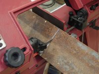
I didn't need the entire length of the angle iron for this project so I started to cut off what I needed. I thought my Harbor Freight 4x6 Horizontal Band Saw would have enough capacity to handle this but it came up about 3/8 of an inch short of being able to cut this material.


20201115-04.jpg

I propped up one end of the angle iron and finished the cut.


20201115-05.jpg

I used the "shim" and a small Kant-Twist Clamp and cut my material into 4 pieces.


20201115-06.jpg

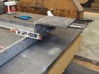
My intent is for these four "brackets" to be welded to the base which will make this a mobile base. HA!


20201115-07.jpg

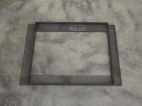
Pieces of left over angle iron from the LBG's Tornado Shelter "Lip" were cut to size to make the base. The pieces are not arranged correctly in the picture. This was just the easiest way to see if everything was essentially square.

I had used a woodworker's aluminum Bar Clamp as calipers to measure the base of the Jointer. The pieces of angle iron were then placed in the Horizontal Band Saw and cut to correct length.

The sawing did take a while but since gravity, with the assistance of a spring, is doing most of the work, I could walk away from the saw and do other things.

This was as far as I got today. I hope to accomplish more on this project tomorrow.

Scott
 
OP
S

sbosecker

Well-known member
Joined
Sep 25, 2012
Messages
3,539
Location
Peachtree City, GA
Monday - November 16, 2020

Managed to get a little more time in the shop today to work on the Delta Jointer Mobile Base.

The first order of business was to see if my planned approach to the way the base pieces fit together was going to work.


20201116-01.jpg 20201116-02.jpg

I took a cutoff from yesterday's work, marked it out and cut it on the Harbor Freight Horizontal Band Saw. I used my Magnet Base Task Light to help illuminate the cut line.


20201116-03.jpg

That seemed to work nicely!

What followed was basically marking out and tedious cutting of the angle iron. This wasn't quick work on the Band Saw but eventually I had made the 8 cuts that were required.


20201116-04.jpg

...and Bob's your uncle.

I probably will need to do a little grinding on a couple of the cuts but it won't take much.


20201116-05.jpg

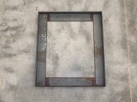
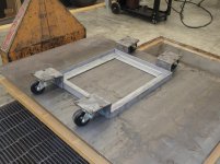
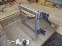
Here's a mockup - of sorts - that gives the basic idea of how these bits will eventually be welded together. The "base" section will be inverted from its present position relative to the caster brackets but I think the picture illustrates the idea.

I'm trying to decide if I should put some gussets on the sides of the caster brackets to stiffen them or if they'll be OK without any additional structure.

Scott
 

AZpilot

Well-known member
Joined
Sep 29, 2012
Messages
413
Location
Mesa, AZ
not being an engineer not sure why gussets would be needed. If welded should be fine. Welded on 3 sides? Then should be ok.
 
OP
S

sbosecker

Well-known member
Joined
Sep 25, 2012
Messages
3,539
Location
Peachtree City, GA
not being an engineer not sure why gussets would be needed. If welded should be fine. Welded on 3 sides? Then should be ok.


AZpilot,


Yeah... My concern - probably unfounded - is that the weight of the 8-inch jointer coupled with the moment arm out to the casters might cause the cantilevered 5-inch angle iron to deflect up a bit. A 1-inch wide rather thin piece of steel welded on each side of the 5-inch diving board would make it into a C-channel and stiffen it dramatically.

It wouldn't be that hard to weld those small pieces onto the caster brackets now but would be more challenging after the caster brackets are welded to the frame.

Best regards,

Scott
 
OP
S

sbosecker

Well-known member
Joined
Sep 25, 2012
Messages
3,539
Location
Peachtree City, GA
Tuesday - November 11, 2020


I managed to get quite a bit of the shop today. Didn't get to the welding phase on my Jointer Mobile Base project quite yet but today's work puts that in reach.


20201117-01.jpg

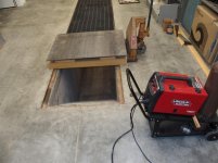
Quite a while ago I bought some 1/2-inch steel plate that I hope to use to make a welding table some day. It's been sitting on a pallet since purchased. I decided I could use the multi-tasking Tornado Shelter to achieve the equivalent of a welding table.


20201117-02.jpg 20201117-03.jpg 20201117-04.jpg

...but before welding can be done I need to get the steel bits cleaned up. I spent some time at the Blasting Cabinet with a couple of pieces and they turned out nice. However, I'm running the Blasting Cabinet with a 30 gallon air compressor (don't have the big boy operational yet) and that poor little thing just was having a hard time keeping up.

I needed to find a way to be more efficient cleaning up the steel.


20201117-05.jpg 20201117-06.jpg

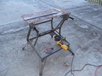
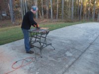
I sat up a WorkMate outside - it was a glorious fall day here today - and knocked the majority of the rust and mill scale off the steel with my angle grinder.


20201117-07.jpg

Final cleanup was done in the Blasting Cabinet. The combination of Angle Grinder & Blasting Cabinet really sped things up.

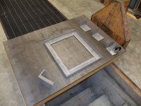
Note the piece of steel - mocked up as a gusset - on the Caster Bracket in the lower right. I may weld pieces like that to the Caster Brackets to stiffen them a bit.


Continued in next post...
 
Last edited:
OP
S

sbosecker

Well-known member
Joined
Sep 25, 2012
Messages
3,539
Location
Peachtree City, GA
Continued...

The next task was to drill holes in the Caster Brackets for bolts to fasten the Casters to the Brackets.


20201117-11.jpg 20201117-12.jpg

I applied some red layout fluid to the Caster Brackets to help the marks made by a Transfer Punch show up better.


20201117-13.jpg

Even with the layout fluid the initial marks made by the Transfer Punch were difficult to see. I struck each location with a center punch and that shows up much better.


20201117-14.jpg

A very large KantTwist Clamp was used to hold the Caster Bracket in position on the Drill Press Table. This variable speed Drill Press allowed me to drill a pilot hole first at around 2000 rpm and then drop the speed down to around 800 rpm to drill a 11/32" hole in the 1/4-inch thick bracket.


Accurately drilling the 16 holes required took longer than I thought it would. The time getting the drill bit lined up with the center punch mark and then getting the Caster Bracket clamped down added up.


20201117-15.jpg

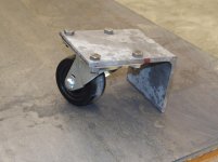
I went to my hardware stash and got a bunch of 3/4-inch long 5/16-inch bolts and some nuts to fasten the Caster to the Bracket.

After the first Caster Bracket I began to develop a rhythm... I had some CD's playing in the music box and I even took a few minutes off to go outside and watch the International Space Station go overhead at 7 o'clock.

It was a great evening!


20201117-16.jpg

In the end it all came together. I'll probably weld the Frame together tomorrow. I don't have enough scrap pieces of 1/8-inch thick x 1-inch wide steel to make all the gussets I would need for the Caster Brackets so I don't know if I'll get to that tomorrow or not.

Scott
 
Last edited:
OP
S

sbosecker

Well-known member
Joined
Sep 25, 2012
Messages
3,539
Location
Peachtree City, GA
Wednesday - November 18, 2020

Today I continued the Jointer Mobile Base project.

Welding began.


20201118-01.jpg

First some tack welds on the Frame.


20201118-02.jpg 20201118-03.jpg
20201118-04.jpg


It's been a while since I've done any welding so this was an adventure. I'm using flux core welding wire since that will allow my toy welder to better handle the 1/4-inch thick material I'm using.


20201118-05.jpg

Grinding the welds.


20201118-06.jpg 20201118-07.jpg

Welding the Caster Brackets to the Frame. I decided to go without any gussets.


Continued in next post...
 
Last edited:
OP
S

sbosecker

Well-known member
Joined
Sep 25, 2012
Messages
3,539
Location
Peachtree City, GA
Continued...


20201118-11.jpg

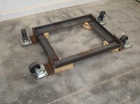
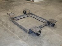
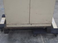
So I have a (seemingly) functional Mobile Base. Clearance off the floor is about 1/2-inch which is fine in my Woodshop. I'll try to see how the Jointer and Mobile Base mates up tomorrow.

Still some cleanup to do and then painting but the heavy lifting is over (I think).

When I left the shop for the evening, the Mobile Base was still radiating heat it had absorbed from the welding operations.

Scott
 

Jayman17

Well-known member
Joined
Feb 6, 2017
Messages
3,820
Location
Seattle, Wa
Scott, what a coincidence, I am making an exact duplicate of your mobile base right now. I picked up a free metal cabinet and repainted that. I made a butcher block oak top for it and will eventually mount a bench top vintage dp on top.
In the process of making the base, yours looks great.

Jay
 
To avoid these ads, REGISTER NOW!
Top Bottom