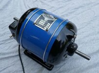
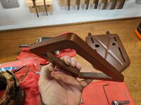
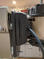
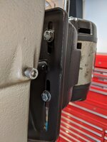
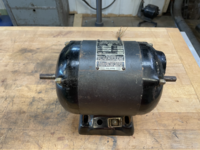
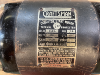
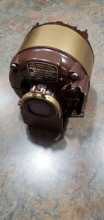
I was requested to outline some of my comparison information about Vintage Craftsman General Purpose Motors by a fellow GJ member. Most of this information was available on the forum prior to the 2021 forum update but has been lost or difficult to locate ever since.
I am not an electrician and my knowledge of motors in general is fairly limited, but I will endeavor to provide some relevant information here. If you are restoring a vintage piece of Craftsman powered tool equipment, chances are you will have one of these motors or a variation of one outlined here.
I welcome your comments, questions, input, and contributions to this thread so that we can all have a resource to assist others.
Craftsman sold most of their power tool equipment in the pre and post WWII eras without motors. You would buy a drill press or similar tool and mount a motor to the tool. Almost all of these tools were belt driven and required an ac motor ranging from ¼ - 2 HP depending on the tool and the needs of the user. These motors typically came in three RPM variations: 1725 RPM, 1750 RPM, and 3450 RPM.
Drill Presses and other tools used 1725/ 1750 RPM motors in 1/4HP, 1/3HP, 1/2HP, 1 HP, and 2HP; although ½ HP seems to be the most common. Table Saws, Sander, Jointers, and other tools used 3450 RPM motors in similar HP ratings. Almost all of these motors were thermally protected utilizing a Klixon Thermal protection switch incorporated into the motor housing.

Most of these motors were not wired with a power cord when purchased and it was left to the owner to wire the motor for their application. Further, most of these motors were reversible and often had dual shaft configurations.

The majority of these motors were capacitor start motors, but a few were split phase motors. Lastly, most of these motors utilized ball bearings; however, a few utilized sleeve bearings. I will try to break down these differences and explain some general design features of these motors before we start to look at the various motors themselves.
Like I said, I am not an electrician so speaking intelligently about horsepower or amperage are not in my skill set. I typically follow the recommend HP listed in the owner’s manual for the power tool I am rebuilding. Since we are talking about vintage machinery, most of the time these tools will include a motor that the previous owner (PO) affixed to the equipment. This is not a given that the PO utilized the correct motor and there are times where the PO used a non-Craftsman motor. I prefer to replace the motor in these instances with a period correct Craftsman motor.
Another thing to be aware of is that Craftsman did not make these motors. Craftsman contacted motor manufacturers to produce these motors for the Craftsman line of tools. This means that most of these motors were produced by GE, Dunlap, Emerson, Packard Electric, Sunlight Electric, Delco to name a few.
Your first starting point for vintage Craftsman powered tools and the motors is the Vintage Machinery site here:
On the Sears Craftsman page, you can find most of the user manuals and parts diagrams you need to rebuild your vintage tools (look for the publication reprints tab). There is a photo index of powered tools as well as a ton of information. One of the first things you should notice is the list of known makers. This list has links to the actual manufacturer of Craftsman power tool you are researching. Locate the model number of what you are looking for and the prefix should lead you to the manufacturer. For example, the 115.6962 motor has a prefix of 115 and was manufactured for Craftsman by the Sunlight Electrical Manufacturing Company or Packard Electric Company. This will aid in determining the age of your tool and possible date of manufacturing.
One of the largest Craftsman power tool communities here on GJ is the Classic Craftsman King Seeley Drill Press thread started by the Awesome FrankLee. In determining the age of these amazing drill presses (DP) we often look for date stamps on the motors associated with the DPs as well as the dates on the capacitors. In general, we can determine the date of manufacturing within a few years with this information along with design features known to evolve in the 4 decades these machines were made.
So you have a power tool and you need a motor, you locate the owner’s manual for your tool on Vintage Machinery and it says you need a ½ HP 1725 RPM motor or you already have a motor but you do not know what type motor you have. Do you need or have a split phase or capacitor start motor? What is the difference between the two and is one better than the other?
Split Phase vs Capacitor Start Motors
Induction motors use an electromagnetic process produced by the run windings in the stator to spin the rotor/ shaft. This rotation on most of the motors we will discuss is reversible to suit the needs of the user. Regardless, induction motors need something extra to interrupt the normal phase of the energized run windings to start the spinning of the rotor. For the motors we are discussing here, there are two methods to accomplish this. If there is no interruption in the run phase of the windings a rotor will likely just wiggle back and forth a very small amount and the motor will hum. On a capacitor start motor this normally means the capacitor is bad. On a split phase motor, this normally means there is a problem with the start phase windings (possibly a break in the winding).

A Capacitor start motor will have a capacitor attached to the motor. In the 115 series motor it is a sardine can size rectangle enclose in the base of the motor. On a 397 series motor, the capacitor may be inside the motor housing or attached to the outside of the stator band in a covered hump. There are motors with more than one capacitor, but we are not going to discuss those motors in this thread. In general terms, a capacitor start motor will start with more torque and more efficiency than a split phase motor. Further, if the capacitor is bad, you can replace it and most likely the motor will run fine.

A split phase motor interrupts the phase of the run windings by energizing a second set of windings in the stator. This second set of windings is referred to as the start phase windings. There will most likely not be a capacitor on these motors, and you should be able to see a physical difference between he two types of windings inside the stator. Regardless, if the motor refuses to start, it is likely there is a break in the start phase windings and fixing this will more than likely be difficult. For this reason, I prefer the capacitor start motor over the split phase motor.
Lastly, when you turn an induction motor on there is a centrifugal switch on the rotor that at a certain rotation speed disengages the start phase of the motor. On a capacitor start motor, this switch disconnects the capacitor. On a split phase motor this switch cuts power to the start phase windings. If you have a motor that will start but then starts to smoke, it is likely the centrifugal switch failing to cut power to the capacitor or start phase windings. When you turn off the motor, as it spins down you should hear a single click. That is the centrifugal switch returning to the start position. If you do not hear this click, you may a problem. I have taken these switches apart to clean, but I have had some bad experiences with switches that worked fine before I disassembled them and later failed to operate correctly. Now I don’t really mess with them and choose to leave them intact during my cleaning process.
Bearings- Ball bearings and Sleeve Bearings
Ball bearings come in an insane number of sizes, types, and variations for an equally insane number of applications. Before we deep dive into ball bearings, what type of ball bearings do you need for your motor? If you have located your owner’s manual on Vintage Machinery and you look at the parts diagram you may see a part number associated with the ball bearing. Something like Part No. 908502 Ball Bearing – New Departure. Well this is some help, but it will take a bit more to locate and order a replacement ball bearing for your motor. So, some intelligent people on Vintage Machinery built a Craftsman Replacement Ball Bearing List for us all to use. Here is the link:
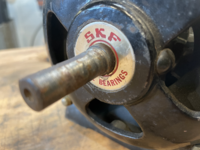
Ball bearings for these motors are typically single row, deep groove, shielded (one side) ball bearings. Some will have extended races, and some will have metric measurements but require a very specific 5/8” inner diameter. There are shielded, sealed and open versions of most of the bearings.
Shielded and Open Bearings
Shielded bearings have a metal shield covering the balls on one side and a double shielded bearing will have a metal shielded on both sides of the bearing. These are pictures of a New Departure 8502 Radial/Deep Groove Ball Bearing One Side Single Seal and One Side Open. This is the actual bearing that is used in the 115 motor and is Craftsman Part No. 908502. Note that typically an open sided ball bearing will have a felt or wool washer inside the motor that will protect the open side.


In the first pic notice the nomenclature stamped into the shield “ND 8502 MADE IN USA”. Often these bearing companies are no longer in business; however, you can still find new/ old stock of these bearings on ebay or you can find comparable bearings from other manufacturers.
Sealed Ball Bearings

Very similar to shielded bearings, sealed bearings use a synthetic material to seal the bearing. Plastics and other materials are normally used and are often black, red, green or blue in color. Sealed ball bearings are typically sealed on both sides and the nomenclature is stamped into the seal or on the edge of the race. In the picture above you can see this is an 88503 bearing. There is no manufacturer name on the bearing, and these are most likely made in china. This is a replacement bearing for the New Departure 88503 felt seal bearing used on Delta grinders. The original New Departure bearing was a one side shielded felt seal bearing. Also note this bearing is an extended race bearing. The race of a bearing is the metal wall on the outside and inside the bore of the bearing. On this bearing the extended race is the inner race, and this ensures a larger coverage of the rotor shaft.
So why are there shielded and sealed bearings? Well one difference is the tolerance the bearing has inside. Depending on application, a ball bearing is made with more or less tolerance to balance speed, use and friction. Another difference is friction itself. Typically, a sealed bearing will generate more friction and produce more heat. Over time this can shorten the life of the bearing but ensure a contaminate free interior. Again, there are millions of uses for ball bearings and most likely an equal number of bearing types. For motors and most other vintage tools, I prefer shielded bearings, but I have used sealed bearings in these applications with no ill effects. I am not a fan of the open ball bearing and when I replace an OEM bearing, I try to do so with a double shielded bearing.
Lastly, the biggest difference in shielded and sealed bearings is more than likely, the price. Sealed bearings are the most common and are almost always cheaper than shielded and even open bearings. For replacement bearings, if you locate new/ old stock on ebay you can pay about $40.00 for a new departure bearing but the same bearing from china may cost $4.00. I recommend you buy bearings from Accurate bearings here:

Bearing Supplier Leader In USA & International | Same-Day Shipping
Top US & international bearing supplier of electric motor bearings and power transmission parts with no minimum orders and same-day shipping. Accurate Bearing Company is the industry's value leader.
www.accuratebearing.com
You will need measurements for the bearing, and you can use this chart to figure out what you need.
If you are ordering bearings from an Asia manufacturer, Japanese manufacturers are higher quality than almost all the Chinese manufacturers. In the end, bearings are an extremely important component in your tool or motor and ensures a level of accuracy and smooth operation. If you plan on opening up a motor or tool to clean/ paint it, then go ahead and take the time to replace the bearings with quality bearings. This is a fairly simple and cheap thing you can do to tune up that tool.
Sleeve Bearings
Sleeve Bearings are simple a wool or felt wick stuffed into a cavity on the end frames of a motor. The wool or felt is lubricated with oil and there is a thin metal shield between the wick and the rotor shaft.

In this picture you can make out the thin metal shield that is the bore for the rotor shaft. behind the shield you can make out the felt wick.

In this pic you can see a rubber cap in the bottom of the pic below the data plate. on a sleeve bearing motor there will be two of these rubber caps, one on each end frame to lubricate each sleeve bearing. I am sure there is some chart out there that tells you how often you should lubricate the sleeve bearings, but I just do it every year and that seems to work for me.
You can imagine that if you over lube the sleeve bearings and the motor is place vertically, it will more than likely leak oil. The mess in general and the less efficient nature of a sleeve bearing makes this my least desirable type of motor to use. It seems to me that the sleeve bearings and split phase motors both seem to be cost cutting methods in motor design; however, like I said, I am not an electrician.
Now let’s talk Craftsman motors.

115.6962 Motor

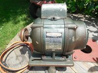
These are probably the most common and iconic vintage Craftsman motors. There are several motors numbers in this family that are essentially the same motor but in different HPs and RPMs. They are capacitor start ball bearing motors and although there are several similar models, I will talk specifically about the 115.6962 Motor. Most Craftsman general purpose motors were never equipped with on/ off switches; however, it is not uncommon to find an on/off switch in one side of the base and the power cord projecting from the other side of the base.
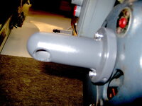
This motor is 32.5 pounds and is 12 ½” long from shaft ends. The housing is 8 5/8” long and 6 ¼” in diameter. The dual rotor shafts are non-keyed ½” shafts; however, the bearings engage the rotor shaft at a wider part and require a 15mm bore.

In this pic you can see the two end frames, they are made of cast iron as is the base. The terminal cover, switch shield, air cone, and condenser shield are all made of sheet steel. The two felt retainer discs are also in the pic as well as the rotor.
This is the centrifugal switch on the rotor of a 115 motor

This is the stator of a 115 motor. Notice the Klixon thermal protection switch (red button) and the lead wires running to the terminal board and switch assembly for the centrifugal switch.

The lead wires in many of these motors are very stiff and brittle. They have a fabric heat shielding on them that is probably asbestos or similar dangerous material. Exercise care when working with these wires to not break them, if they break close to the windings, it will be very hard to replace them. If you do need to replace a lead wire or extend a broken one, you need to use a high heat lead wire like 16-gauge stranded silicone insulated wire.

This is a pic of the terminal end frame. note the back side of the Klixon, terminal board, and switch assembly for the centrifugal switch in the center. When the motor is at rest or spinning slowly the centrifugal switch is extended on the rotor shaft and is in contact with this switch allowing power to the capacitor (or in a split phase motor, to the start phase windings). Once the rotor spins to a specific speed, the fingers on the centrifugal switch spread and compress the switch causing it to disengage the switch assembly.

This pic is a outside looking in of the terminal board. Notice the two lead wires visible, these can be reversed to reverse the direction of the motor rotation.

In this pic you can see (from left to right) the end frame, open side of the ball bearing, spring washer, fiber gasket, end cap, felt seal, and felt seal cover. One of the cool design features of these 115 motors is that you can access the bearing without opening the motor.

This is another pic of a terminal end frame; however, notice the metal rectangle on the right side. This is the capacitor on these old 115 motors. These are commonly referred to as sardine can capacitors and are no longer produced. If your capacitor is bad, you will need to replace it with a similar spec round capacitor. This is one of the drawbacks of these motors, there is very little room in the base of the motor and a round capacitor will not fit into the base without some modification. A search for Hoorn here on the GJ should provide some pics for how he fabricated a spacer for a motor to fit a round capacitor.

This pic is the data stamped on one of these sardine can capacitors. Should you need to replace the capacitor make sure you get a comparable one with similar rated MFD and voltage. Also, note the date of manufacture 5-2-50. Chances are this motor was purchased with the drill press it was affixed to and could help in determining the age of the drill press.
One of the largest benefits to the 115 motor is that it cleans up nicely. Just cleaning and repainting are fairly simple but the stator band on these motors was removable and often the original is too far gone.

The original stator band was a polished steel band with satin 1/8” lines on it. In the pic above you can see some of the original finish that was left under the data plate. I prefer to use a piece of sheet aluminum cut to the same size.

Next, I polish the aluminum

Then I apply 1/8” vinyl masking and scuff the exposed aluminum with a scotch-brite pad.

The finished product is fairly close to the original.

With new bearings, a fresh coat of paint and a newly fabricated stator band, this motor looks and runs great.
That covers this update, I will expand on other motors in the coming days.
Thanks for the interest.
Last edited: