To avoid these ads, REGISTER NOW!

The Vintage Craftsman GP Motor Thread

11b30b4

Well-known member
Joined
Jul 16, 2020
Messages
1,029
Location
GA
full


I was requested to outline some of my comparison information about Vintage Craftsman General Purpose Motors by a fellow GJ member. Most of this information was available on the forum prior to the 2021 forum update but has been lost or difficult to locate ever since.

I am not an electrician and my knowledge of motors in general is fairly limited, but I will endeavor to provide some relevant information here. If you are restoring a vintage piece of Craftsman powered tool equipment, chances are you will have one of these motors or a variation of one outlined here.

I welcome your comments, questions, input, and contributions to this thread so that we can all have a resource to assist others.

Craftsman sold most of their power tool equipment in the pre and post WWII eras without motors. You would buy a drill press or similar tool and mount a motor to the tool. Almost all of these tools were belt driven and required an ac motor ranging from ¼ - 2 HP depending on the tool and the needs of the user. These motors typically came in three RPM variations: 1725 RPM, 1750 RPM, and 3450 RPM.

Drill Presses and other tools used 1725/ 1750 RPM motors in 1/4HP, 1/3HP, 1/2HP, 1 HP, and 2HP; although ½ HP seems to be the most common. Table Saws, Sander, Jointers, and other tools used 3450 RPM motors in similar HP ratings. Almost all of these motors were thermally protected utilizing a Klixon Thermal protection switch incorporated into the motor housing.

full


Most of these motors were not wired with a power cord when purchased and it was left to the owner to wire the motor for their application. Further, most of these motors were reversible and often had dual shaft configurations.

full


The majority of these motors were capacitor start motors, but a few were split phase motors. Lastly, most of these motors utilized ball bearings; however, a few utilized sleeve bearings. I will try to break down these differences and explain some general design features of these motors before we start to look at the various motors themselves.

Like I said, I am not an electrician so speaking intelligently about horsepower or amperage are not in my skill set. I typically follow the recommend HP listed in the owner’s manual for the power tool I am rebuilding. Since we are talking about vintage machinery, most of the time these tools will include a motor that the previous owner (PO) affixed to the equipment. This is not a given that the PO utilized the correct motor and there are times where the PO used a non-Craftsman motor. I prefer to replace the motor in these instances with a period correct Craftsman motor.

Another thing to be aware of is that Craftsman did not make these motors. Craftsman contacted motor manufacturers to produce these motors for the Craftsman line of tools. This means that most of these motors were produced by GE, Dunlap, Emerson, Packard Electric, Sunlight Electric, Delco to name a few.

Your first starting point for vintage Craftsman powered tools and the motors is the Vintage Machinery site here:


On the Sears Craftsman page, you can find most of the user manuals and parts diagrams you need to rebuild your vintage tools (look for the publication reprints tab). There is a photo index of powered tools as well as a ton of information. One of the first things you should notice is the list of known makers. This list has links to the actual manufacturer of Craftsman power tool you are researching. Locate the model number of what you are looking for and the prefix should lead you to the manufacturer. For example, the 115.6962 motor has a prefix of 115 and was manufactured for Craftsman by the Sunlight Electrical Manufacturing Company or Packard Electric Company. This will aid in determining the age of your tool and possible date of manufacturing.

One of the largest Craftsman power tool communities here on GJ is the Classic Craftsman King Seeley Drill Press thread started by the Awesome FrankLee. In determining the age of these amazing drill presses (DP) we often look for date stamps on the motors associated with the DPs as well as the dates on the capacitors. In general, we can determine the date of manufacturing within a few years with this information along with design features known to evolve in the 4 decades these machines were made.

So you have a power tool and you need a motor, you locate the owner’s manual for your tool on Vintage Machinery and it says you need a ½ HP 1725 RPM motor or you already have a motor but you do not know what type motor you have. Do you need or have a split phase or capacitor start motor? What is the difference between the two and is one better than the other?

Split Phase vs Capacitor Start Motors

Induction motors use an electromagnetic process produced by the run windings in the stator to spin the rotor/ shaft. This rotation on most of the motors we will discuss is reversible to suit the needs of the user. Regardless, induction motors need something extra to interrupt the normal phase of the energized run windings to start the spinning of the rotor. For the motors we are discussing here, there are two methods to accomplish this. If there is no interruption in the run phase of the windings a rotor will likely just wiggle back and forth a very small amount and the motor will hum. On a capacitor start motor this normally means the capacitor is bad. On a split phase motor, this normally means there is a problem with the start phase windings (possibly a break in the winding).

full


A Capacitor start motor will have a capacitor attached to the motor. In the 115 series motor it is a sardine can size rectangle enclose in the base of the motor. On a 397 series motor, the capacitor may be inside the motor housing or attached to the outside of the stator band in a covered hump. There are motors with more than one capacitor, but we are not going to discuss those motors in this thread. In general terms, a capacitor start motor will start with more torque and more efficiency than a split phase motor. Further, if the capacitor is bad, you can replace it and most likely the motor will run fine.

full


A split phase motor interrupts the phase of the run windings by energizing a second set of windings in the stator. This second set of windings is referred to as the start phase windings. There will most likely not be a capacitor on these motors, and you should be able to see a physical difference between he two types of windings inside the stator. Regardless, if the motor refuses to start, it is likely there is a break in the start phase windings and fixing this will more than likely be difficult. For this reason, I prefer the capacitor start motor over the split phase motor.

Lastly, when you turn an induction motor on there is a centrifugal switch on the rotor that at a certain rotation speed disengages the start phase of the motor. On a capacitor start motor, this switch disconnects the capacitor. On a split phase motor this switch cuts power to the start phase windings. If you have a motor that will start but then starts to smoke, it is likely the centrifugal switch failing to cut power to the capacitor or start phase windings. When you turn off the motor, as it spins down you should hear a single click. That is the centrifugal switch returning to the start position. If you do not hear this click, you may a problem. I have taken these switches apart to clean, but I have had some bad experiences with switches that worked fine before I disassembled them and later failed to operate correctly. Now I don’t really mess with them and choose to leave them intact during my cleaning process.

Bearings- Ball bearings and Sleeve Bearings

Ball bearings come in an insane number of sizes, types, and variations for an equally insane number of applications. Before we deep dive into ball bearings, what type of ball bearings do you need for your motor? If you have located your owner’s manual on Vintage Machinery and you look at the parts diagram you may see a part number associated with the ball bearing. Something like Part No. 908502 Ball Bearing – New Departure. Well this is some help, but it will take a bit more to locate and order a replacement ball bearing for your motor. So, some intelligent people on Vintage Machinery built a Craftsman Replacement Ball Bearing List for us all to use. Here is the link:


Ball bearings for these motors are typically single row, deep groove, shielded (one side) ball bearings. Some will have extended races, and some will have metric measurements but require a very specific 5/8” inner diameter. There are shielded, sealed and open versions of most of the bearings.

Shielded and Open Bearings

Shielded bearings have a metal shield covering the balls on one side and a double shielded bearing will have a metal shielded on both sides of the bearing. These are pictures of a New Departure 8502 Radial/Deep Groove Ball Bearing One Side Single Seal and One Side Open. This is the actual bearing that is used in the 115 motor and is Craftsman Part No. 908502. Note that typically an open sided ball bearing will have a felt or wool washer inside the motor that will protect the open side.

full


full


In the first pic notice the nomenclature stamped into the shield “ND 8502 MADE IN USA”. Often these bearing companies are no longer in business; however, you can still find new/ old stock of these bearings on ebay or you can find comparable bearings from other manufacturers.

Sealed Ball Bearings

full


Very similar to shielded bearings, sealed bearings use a synthetic material to seal the bearing. Plastics and other materials are normally used and are often black, red, green or blue in color. Sealed ball bearings are typically sealed on both sides and the nomenclature is stamped into the seal or on the edge of the race. In the picture above you can see this is an 88503 bearing. There is no manufacturer name on the bearing, and these are most likely made in china. This is a replacement bearing for the New Departure 88503 felt seal bearing used on Delta grinders. The original New Departure bearing was a one side shielded felt seal bearing. Also note this bearing is an extended race bearing. The race of a bearing is the metal wall on the outside and inside the bore of the bearing. On this bearing the extended race is the inner race, and this ensures a larger coverage of the rotor shaft.

So why are there shielded and sealed bearings? Well one difference is the tolerance the bearing has inside. Depending on application, a ball bearing is made with more or less tolerance to balance speed, use and friction. Another difference is friction itself. Typically, a sealed bearing will generate more friction and produce more heat. Over time this can shorten the life of the bearing but ensure a contaminate free interior. Again, there are millions of uses for ball bearings and most likely an equal number of bearing types. For motors and most other vintage tools, I prefer shielded bearings, but I have used sealed bearings in these applications with no ill effects. I am not a fan of the open ball bearing and when I replace an OEM bearing, I try to do so with a double shielded bearing.

Lastly, the biggest difference in shielded and sealed bearings is more than likely, the price. Sealed bearings are the most common and are almost always cheaper than shielded and even open bearings. For replacement bearings, if you locate new/ old stock on ebay you can pay about $40.00 for a new departure bearing but the same bearing from china may cost $4.00. I recommend you buy bearings from Accurate bearings here:


You will need measurements for the bearing, and you can use this chart to figure out what you need.


If you are ordering bearings from an Asia manufacturer, Japanese manufacturers are higher quality than almost all the Chinese manufacturers. In the end, bearings are an extremely important component in your tool or motor and ensures a level of accuracy and smooth operation. If you plan on opening up a motor or tool to clean/ paint it, then go ahead and take the time to replace the bearings with quality bearings. This is a fairly simple and cheap thing you can do to tune up that tool.

Sleeve Bearings

Sleeve Bearings are simple a wool or felt wick stuffed into a cavity on the end frames of a motor. The wool or felt is lubricated with oil and there is a thin metal shield between the wick and the rotor shaft.

full


In this picture you can make out the thin metal shield that is the bore for the rotor shaft. behind the shield you can make out the felt wick.

full


In this pic you can see a rubber cap in the bottom of the pic below the data plate. on a sleeve bearing motor there will be two of these rubber caps, one on each end frame to lubricate each sleeve bearing. I am sure there is some chart out there that tells you how often you should lubricate the sleeve bearings, but I just do it every year and that seems to work for me.

You can imagine that if you over lube the sleeve bearings and the motor is place vertically, it will more than likely leak oil. The mess in general and the less efficient nature of a sleeve bearing makes this my least desirable type of motor to use. It seems to me that the sleeve bearings and split phase motors both seem to be cost cutting methods in motor design; however, like I said, I am not an electrician.

Now let’s talk Craftsman motors.

full


115.6962 Motor

full


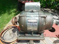
These are probably the most common and iconic vintage Craftsman motors. There are several motors numbers in this family that are essentially the same motor but in different HPs and RPMs. They are capacitor start ball bearing motors and although there are several similar models, I will talk specifically about the 115.6962 Motor. Most Craftsman general purpose motors were never equipped with on/ off switches; however, it is not uncommon to find an on/off switch in one side of the base and the power cord projecting from the other side of the base.

This motor is 32.5 pounds and is 12 ½” long from shaft ends. The housing is 8 5/8” long and 6 ¼” in diameter. The dual rotor shafts are non-keyed ½” shafts; however, the bearings engage the rotor shaft at a wider part and require a 15mm bore.

full


In this pic you can see the two end frames, they are made of cast iron as is the base. The terminal cover, switch shield, air cone, and condenser shield are all made of sheet steel. The two felt retainer discs are also in the pic as well as the rotor.

This is the centrifugal switch on the rotor of a 115 motor

full


This is the stator of a 115 motor. Notice the Klixon thermal protection switch (red button) and the lead wires running to the terminal board and switch assembly for the centrifugal switch.

full


The lead wires in many of these motors are very stiff and brittle. They have a fabric heat shielding on them that is probably asbestos or similar dangerous material. Exercise care when working with these wires to not break them, if they break close to the windings, it will be very hard to replace them. If you do need to replace a lead wire or extend a broken one, you need to use a high heat lead wire like 16-gauge stranded silicone insulated wire.

full


This is a pic of the terminal end frame. note the back side of the Klixon, terminal board, and switch assembly for the centrifugal switch in the center. When the motor is at rest or spinning slowly the centrifugal switch is extended on the rotor shaft and is in contact with this switch allowing power to the capacitor (or in a split phase motor, to the start phase windings). Once the rotor spins to a specific speed, the fingers on the centrifugal switch spread and compress the switch causing it to disengage the switch assembly.

full


This pic is a outside looking in of the terminal board. Notice the two lead wires visible, these can be reversed to reverse the direction of the motor rotation.

full


In this pic you can see (from left to right) the end frame, open side of the ball bearing, spring washer, fiber gasket, end cap, felt seal, and felt seal cover. One of the cool design features of these 115 motors is that you can access the bearing without opening the motor.

full


This is another pic of a terminal end frame; however, notice the metal rectangle on the right side. This is the capacitor on these old 115 motors. These are commonly referred to as sardine can capacitors and are no longer produced. If your capacitor is bad, you will need to replace it with a similar spec round capacitor. This is one of the drawbacks of these motors, there is very little room in the base of the motor and a round capacitor will not fit into the base without some modification. A search for Hoorn here on the GJ should provide some pics for how he fabricated a spacer for a motor to fit a round capacitor.

full


This pic is the data stamped on one of these sardine can capacitors. Should you need to replace the capacitor make sure you get a comparable one with similar rated MFD and voltage. Also, note the date of manufacture 5-2-50. Chances are this motor was purchased with the drill press it was affixed to and could help in determining the age of the drill press.

One of the largest benefits to the 115 motor is that it cleans up nicely. Just cleaning and repainting are fairly simple but the stator band on these motors was removable and often the original is too far gone.

full


The original stator band was a polished steel band with satin 1/8” lines on it. In the pic above you can see some of the original finish that was left under the data plate. I prefer to use a piece of sheet aluminum cut to the same size.

full


Next, I polish the aluminum

full


Then I apply 1/8” vinyl masking and scuff the exposed aluminum with a scotch-brite pad.

full


The finished product is fairly close to the original.

full


With new bearings, a fresh coat of paint and a newly fabricated stator band, this motor looks and runs great.

full


That covers this update, I will expand on other motors in the coming days.

Thanks for the interest.
 
Last edited:
To avoid these ads, REGISTER NOW!

Davefr

Well-known member
Joined
Jan 7, 2010
Messages
11,839
Location
OR
Wow, what a great post!! I love your idea of making a replacement stator band. Those can often be pretty rusty.

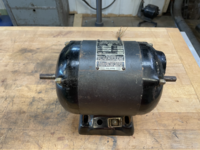
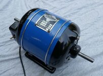
Here's an earlier CM motor. I really like the color scheme.
 

Attachments

  • P1090160.jpg
    P1090160.jpg
    85.4 KB · Views: 136
  • P1090161.jpg
    P1090161.jpg
    109 KB · Views: 123
  • P1090162.jpg
    P1090162.jpg
    101.6 KB · Views: 81
OP
1

11b30b4

Well-known member
Joined
Jul 16, 2020
Messages
1,029
Location
GA
Davefr, that is an amazing looking motor. Do you know the model number and who manufactured it? All I can see on the data tag is the cage code and it looks like it was possibly made by Dunlap.
 

Cruzan80

Well-known member
Joined
Jul 22, 2015
Messages
4,273
Location
Denver, CO
Not Dunlap, it is an earlier CM motor. I know WT made some for Craftsman, can get codes off mine once I dig them out.
 

Davefr

Well-known member
Joined
Jan 7, 2010
Messages
11,839
Location
OR
Davefr, that is an amazing looking motor. Do you know the model number and who manufactured it? All I can see on the data tag is the cage code and it looks like it was possibly made by Dunlap.
It's Cat No 5608D. I have no idea who made it.
 

JoCoSawdust

Well-known member
Joined
Nov 19, 2018
Messages
2,416
Location
Eastern NC
Fantastic thread 11B! I don't know where you find time to do this but your archiving skills are unsurpassed. I've often thought about starting a similar thread but 1) I **** at archiving stuff and 2), I'm lazy in the evenings. This will be a great source for guys just getting into the game. There's a lot of great info on these motors out there but most threads are incomplete. I've spent a lot of time searching to learn what I needed to know.

As far as the OEMs, the quick answer on the 115s is that Packard made them. Splitting hairs, GM bought Packard Electric Co. in 1932 then consolidated more by adding Sunlight Electric in 1943 (ref: Vintage Machinery site).

Dave, +1 on a beautiful motor! I've got one of those in the queue. Mid-to-late 30s. I've been told they were made by Diehl although I've seen no evidence of that with my own eyes. They seem to have produced a lot more 3450 rpm versions of those than 1725s. I need a 1725 version of that motor for my WT bandsaw but it's proving to be an elusive *******.

11B, with your permission, I'd like to add pics of a few of my motors on here. There's a surprising number of variations out there, especially in the early days.

Now....to get to reading this thing!!
 
Last edited:
OP
1

11b30b4

Well-known member
Joined
Jul 16, 2020
Messages
1,029
Location
GA
Cruzan, you may be correct. I look forward to any additional information you can shed on this model of motor.

Davefr, yep that is the only relevant number I see on the data plate and that is a rather unique data plate and CM logo. Regardless, I love the very sleek look of that motor and the high gloss paint and color choice really pop. I believe that motor in 1725 or 1750 RPMs would be a perfect match for a Craftsman Mohawk DP.

JoCoSawdust, thank you brother. I know I get long winded on these types of post but there is always someone out there who needs that additional information. You are correct, I would have killed to have this information presented in a similar format back when I started messing with rebuilding vintage machinery.

Lastly, you do not need my permission to add to this thread. I welcome any and all additions, afterall, I only have a few of these different types of motors and would like to see this thread grow to cover most of the vintage CM motors.


Update:

full


397.19821 Motor

full


This motor came attached to my 103.22500 belt disc sander. Once I cracked this motor open it immediately became my favorite Craftsman motor. I posted as much in my sander rebuild thread and it is actually why I was asked to make this thread.

According to Vintage Machinery, the 397 prefix tools were manufactured for Craftsman by the Delco Products Corporation. This seems to include a huge number of the block and bench grinders and it makes sense that they would also produce motors. I am sure many of us have seen some pics of people just using 115 series motors as grinders and polishers, after all, a grinder is basically just a motor with threaded shafts on each end.

This motor is 20 pounds and is 13 ½” long from shaft ends. The housing is 9 1/4” long and 6 ¼” in diameter. The dual rotor shafts are ¼” keyed and are 5/8” shafts; however, the bearings engage the rotor shaft at a wider part and require a 17mm bore. On my motor the bearings were Hoover brand 77203 double shielded ball bearings measuring 40mm x 12mm with a 17mm bore.

full


This is a ½ HP 3450 RPM 115 V 60 Cyc 10-amp thermal protected capacitor start motor. Oddly, the data tag states, “Develops 1 HP”. I do not know if this is common on all motors that they “develop” more horsepower than they are rated at, but I have not seen this on any of the other motors I have. Anyway, it also has continuous duty ball bearings.

Here is a pic of the original tag.

full


And this is a pic of the replacement tag that Mattblast and I worked to develop.

full


This motor actually has a removeable base, but the stator band is not removable. The stator is tac welded into the rolled steel stator band. On newer motors of similar design, the base would also be welded to the stator band. Unfortunately, I did not take a bunch of good pics of this motor when I rebuilt it. At the time I was rebuilding another 115 motor and the blet disc sander all at the same time so this pic is a bit confusing; however, in this pic you can sort of make out the cleaned up rotor with the centrifugal switch and bearings resting on the yellow parts bin on the left side. Above the rotor are the two freshly painted end frames. The end frames on this motor are cast aluminum or similar material.

full


So why the heck is this my favorite motor? First, it is much lighter than the cast iron motors and when you are bent over and trying to mount a motor to a pedestal column, that is a large consideration. Second, I love the efficient design. The materials used are certainly a cost cutting effort by the manufacturer, but they are also just as solid and sound as the older cast iron motors. By the time this motor was in production, stamped steel was in wide use and casting was seeing less use in all industries. This is a pic of the inside of the terminal end of the motor.

full


Notice the capacitor is enclosed inside the motor housing. I like this design because the exterior of the motor remains fairly streamlined. Also notice the terminal board on the right side is affixed to the stamped steel stator baffle by bent steel prongs. There is an effort made in this design to eliminate loose parts such as the bolts and screws that would fasten the terminal board to the motor in other designs such as the 115 motor. Even the switch that engages with the centrifugal switch is minimal in its design. It is just that ¼” wide copper protrusion coming from the terminal board. Another design feature is that most of the wire connectors are blade quick connectors unlike older model motors that use ring and spade connectors.

full


In this pic we see the outside o the terminal end frame. Note the Klixon thermal protection switch in red near the top. Unlink almost all other craftsman general purpose and tool motors, the 397 motor comes with an on/ off switch built in.

full


This is a pic of the same end with the terminal cover removed.

full


This is a pic of the inside of the terminal end frame. You can see the Klixon switch installed and bore opening for the bearing.

full


This is a pic of the stator masked off and a painted stator band. Cleaning up this motor and repainting it was a snap and is the final reason this is my favorite motor. It may not be the nicest looking vintage Craftsman motor, but it is damn simple and extremely easy to work on. Anything short of rewinding is a user lever task.

full


These 397 motors clean up nicely and run great. I can not say they will last as long as the cast iron 115 motors, but they are a sold motor and I love them.

That covers this update, I will expand on other motors in the coming days.

Thanks for the interest.
 
Last edited:

Hoorn

Well-known member
Joined
May 19, 2020
Messages
1,140
Location
Glendora, CA
11b, brilliant outline, fantastic pictures that are big, clear and detailed. Not only will this help so many GJ'ers with their 115 and 397 motors, but it will inspire others to roll up their sleeves and bring a few of these classic motors out from the dark corner of the garage for some rehab.

Because you mentioned my capacitor mod, I'll toss those pics on here so GJ'ers don't have to search them out.

Tip o' the cap 11b, GREAT thread. Can't wait to see JoCo's contributions.
 
OP
1

11b30b4

Well-known member
Joined
Jul 16, 2020
Messages
1,029
Location
GA
Hoorn, thank you and yes please add the pics of the capacitor spacer modification to the 115 motor.

Shiftless, thank you.

Davefr, several people on FrankLee’s Craftsman Drill Thread have them. It is a really cool motor idea, but I would have preferred a wider range of variable speeds. Speeds lower in range around 150 and 200 RPMs would make is usable for band saws for cutting metal and other applications. Regardless, it is a cool motor.


Update:

full


113.19352 Motor

full


These motors are fairly common. They are smaller and weight less than a lot of the other Craftsman comparable models. The 113 prefix indicates that these motors were produced by the Emerson Electric Company. It is not uncommon to find these motors paired with Emerson Era Drill Presses like the 4th generation DP I have in my collection. However, this 113 motor came paired with a 1963 150 series DP. This is also the motor that taught me to leave the centrifugal switch alone.

full


This 113 motor is a ½ HP, 1725 RPMs, single split phase sleeved bearings general purpose motor. Based on the data plate the motor was built in 1963 and played a part in determining the age of the drill press it was attached with. In the pic above you can also see the rubber plug cap where you add oil to the sleeve bearings. The motor is a single shaft reversable rotation motor with a ½” non-keyed shaft. The motor is 10 3/8” long from shaft end to end frame and weighs 17.5 pounds. The motor housing is 8 ¾” long and 6” in diameter.

full


This motor also demonstrates the growing conformity in AC motors across many industries. Today there are a number of “standards” that AC motors fall into and they really began to expand across the manufacturers in the mid 60s. On this 113 motor this conformity is evident in the frame base.

full


These standardize frame sizes were developed to ensure a wide range of motors could be mounted to an equally wide range to tools and other equipment as well as consumer appliances. Indeed, these standards are now prominently dominated by the heating and cooling industry as well as other appliances such as washing machines. If you look at web sites such as Granger and Zoro you can find hundreds of motors. Normally you would search for a motor based on application, HP, RPMs, physical size, mounting position (horizontal, vertical, or any) and mounting frame size (normally expressed in NEMA standards).

Here is a link to chart of the NEMA frame dimensions:


In the pic below, the 113 motor is mounted on the motor mount for a 150 drill press. If you look closely you can see that there is a frame base between the motor and the motor mount. On the end closest, you can make out a rubber hub ring. The hub ring isolates the vibration of the motor from the tool or appliance it is mounted on. The hub rings fit on the motor end frames and sit in the cradle of the NEMA frame. Next you should see two metal quarter radius metal clamps that connect with a bolt and nut at the apex of the hub ring. These metal clamps secure the motor to the NEMA frame. The frame is made from stamped steel.

full


This is the inside of the terminal cover on the terminal end of the motor. The end frames are cast aluminum and have stamped steel inserts for the sleeve bearings.

full


This is the inside of the terminal end frame and you can see the sleeve bearing. Also notice that this motor does not incorporate a Klixon thermal protection switch or on/off switch.

full


This is a pic of the centrifugal switch on the rotor. The springs and weights on these centrifugal switches are calibrated to expand or compress the switch at a certain rotation speed. To disassemble the switch you need to pull on the springs and I can only assume I stretch one or both to a point that threw the switch out of calibration. Once I cleaned all the parts on this motor, I reassembled the switch and began to fail to disengage the start phase. I was seeing smoke about 20 seconds after I powered up the motor. I eventually got the motor to operate properly when sitting on my bench but when I mounted it vertically, the smoke came back and I eventually decided to replace this motor with the trusty 115 motor. Besides, like I have previously said, I am also not a fan of the sleeve bearing.

full


Speaking of sleeve bearings, these two pics show all the washer seals that are on each end of the rotor shaft to keep all that oil from dripping out of the motor.

full


full


For a motor that is in direct contact with saw dust and metal shavings this just seems way to messy to me.

Like many of the other Craftsman GP motors this one is also reversable.

full


Here is a good pic of the stator. The stator band is tac welded to the stator and is made from stamped steel. Notice the run phase windings are a reddish copper color and the start phase windings are thinner and are a goldish color. The colors are not that important because different manufacturers use different colors of lacquer to coat the winds or they will use clear lacquer. For me the easiest way to see the difference between the two types of windings is the thickness of the wires used. As far as I know, the thinner windings are always the start phase. It is probably a bit late into this thread to mention it but there are a ton of videos on YouTube that explain every aspect of induction motors and you should take the time to educate yourself before you decide to crack open a motor.

full


Anyway, I am not a fan of this motor, but it does what it is expected to do as long as you don’t mess with the centrifugal switch. They do clean up nicely and as you will see in the next motor, I am not completely against using them.

full


full


113.19665 Motor

full


This is another 113 motor but this one is in 1/3 HP 1725 RPMs. It is a split phase sleeve bearing general purpose motor that is mounted to my 103 series band saw. It is a single shaft reversible motor with a ½” non keyed shaft. It is 9 ¼” from shaft end to end frame. The motor housing is 7 ¾” long and 6” in diameter. Keep in mind that this motor also uses a NEMA cradle frame and the frame will be a different dimension than the motor. The motor weighs 17.5 pounds which is a significant weight savings compared to a 115 cast iron motor.

full


This is the data plate for this motor and notice the rubber plug cap to oil the sleeve bearings. My best guess is that the K60 marking is a date code and given the age of the band saw it accompanied, this motor was probably made in 1960. If you are interested in how to remove these data plate for cleaning and painting the motor, check out my 103 band saw rebuild thread. Links to all the threads I start are on my workshop thread in my signature.

full


This motor was actually vertically mounted into a homemade drum sander that accompanied my band saw so it did not come with a NEMA frame. I found a frame that fit the motor and used the rubber end rings and clamps from the 113.19352 motor since I was not using it. You can find replacement rings and clamps online from a number of sites.

full


These are the end frames being painted. I did not mess with fully stripping them since the paint was in good shape, so I just masked the sleeve bearings and over-sprayed them, lazy, I know.

full


This is a pic of the terminal board with the terminal cover removed.

full


This is the inside of the terminal end frame and again notice there is no Klixon thermal protection switch. Also, you can see the inside of the stator and identify the start phase windings and run phase windings. Like the other 113 motor this stator band is tac welded to the stator and is made from stamped steel. The end frames are cast aluminum with stamped steel inserts for the sleeve bearings.

full


In this pic, I am reassembling the motor. Notice the rotor in the top left and I did not disassemble the centrifugal switch on this motor so, naturally, it runs perfectly once I assemble it. Also, on the right side you can see the rubber end rings, oil plugs, terminal cover, mounting ¼ radius clamps and the long stator studs.

As with all Craftsman motors, it cleans up nicely and looks great repainted.

full


Well that is the update so far. I look forward to yall contributing to the thread. I have a few more motors to cover but it will eb a while before I break them open.

Again, thanks for the interest.
 

Hoorn

Well-known member
Joined
May 19, 2020
Messages
1,140
Location
Glendora, CA
As 11b laid out, capacitor replacement for the 115 motor can pose a problem. Unless you have spare motors with which you can pull an old sardine can style capacitor from, your only other option is a modern, round capacitor. Since the original capacitor location is under the base, even the smallest round capacitors are wide enough so the base can't sit flat on the motor mount, it is anywhere from 1/4" too 3/8" proud.

I got a 1/2" thick piece of hardwood and cut it to the same dimensions as the bottom of the base to use as a spacer. I left as much wood as possible while cutting the inside square for strength. I painted it several times with primer and then hammered paint to give it a "cast iron" texture, then finished with the same color as the base. The closest brown I found for the power bronze machines is Montana Gold Shock Dark Brown which also has a matte finish. Once "clamped" between the motor mount and the base, it doesn't move around at all. You will need longer screws than OEM to compensate.

At any rate, the spacer blends into the base and keeps the motor streamlined and without the need to fabricate a round metal carrier on the outside.
 

Attachments

  • 65165.jpeg
    65165.jpeg
    477.5 KB · Views: 128
  • 65167.jpeg
    65167.jpeg
    321.5 KB · Views: 122
  • 65161.jpeg
    65161.jpeg
    420.8 KB · Views: 128
  • 65110.jpeg
    65110.jpeg
    313.8 KB · Views: 126
  • 65111.jpeg
    65111.jpeg
    422.4 KB · Views: 122
  • 65101.jpeg
    65101.jpeg
    301.7 KB · Views: 106
  • 65170.jpeg
    65170.jpeg
    327.5 KB · Views: 113
Last edited:

JoCoSawdust

Well-known member
Joined
Nov 19, 2018
Messages
2,416
Location
Eastern NC
Great details on the motor internals 11B. This thread can become the go-to source for Craftsman branded motors.

Excellent job on the capacitor housing Hoorn. Hopefully I never have to do that but if I do.........

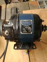
I'm trying to get my ducks in a row to post some useful info in here. I'm horrible at taking pictures as I go through something. For now, here's a couple of split phase motors as mentioned by 11B upthread. Different branding, different model numbers but pretty much the same motor. 1/3hp ball bearings. The Companion 115.5454 on the left is from 1939. With the polished steel stator band (aluminum reproduction in the picture) and brass acorn nuts, I think it's a very elegant motor. The Dunlap 115.6759 on the right is from 1944 and has a painted steel stator band. It originally had hex nuts instead of acorns securing the end bells. I strayed from the original paint scheme (all black) and regret it. The switch on the Dunlap is an aftermarket switch as this one was missing the original, as seen on the Companion. The only internal differences I found on these were the centrifugal switch (slightly smaller on the Companion) and the thermal cut out switch. The T switch in the Companion lacked the bakelite (or whatever) housing we're used to seeing. It was all exposed copper.

Both of these motors use New Departure 8013 bearings which are still available from Accurate Bearing. With as many motors as I've been going through lately, I've become a fan of flushing and repacking original bearings unless the originals are just trashed. My wife's vacuum sealer in her kitchen comes in handy to get that fresh grease into the nooks and crannies. This, of course, happens very, very late at night under cover of darkness.

I like finding these old 1/3hp split phase motors. They're great for smaller machines, freeing up my larger motors for where they're needed. There's also the added benefit of not having to worry about a flat cap. So far, I've only found one of these I couldn't save due to a trashed start winding.

IMG_0788.JPGIMG_0939.JPG
 
Last edited:

Cruzan80

Well-known member
Joined
Jul 22, 2015
Messages
4,273
Location
Denver, CO
JoCo, curious as to your estimation of the age of the Companion motor on the left. I have one as well, with lots of bright shiny chrome. I know Companion was phased out for Dunlap circa 1939, but then made a resurgence in the late 50's/60's? Cord is disintegrating, and the motor is buried.

When I finally get some floor space cleaned up, will take some pics and show off some of the oddballs I have. Sears appliance motor on a spray compressor (later 40's), sears lathe motor, etc.
 

JoCoSawdust

Well-known member
Joined
Nov 19, 2018
Messages
2,416
Location
Eastern NC
Should be stamped on the data plate Cuzan. The Companion is mounted on a DP now and I can't really get an angle for a decent pic. I'll see if I can snap a pic of the Dunlap date. Looking forward to seeing your motors.
 

Modern Garage

Well-known member
Joined
Mar 26, 2015
Messages
583
Location
Southern Minnesota
Here are the pics from my Sears Motor thread from last year if they're any help. At that time we determined the blue Companion motor was from approx 1937 and the stamping at the border of the tag was apparently meaningless. The other motor date codes seemed to be reliable.
Joe
 

Attachments

  • 0812201825a.jpg
    0812201825a.jpg
    150.6 KB · Views: 86
  • 0812201826.jpg
    0812201826.jpg
    162.6 KB · Views: 83
  • 0813200915.jpg
    0813200915.jpg
    330.4 KB · Views: 76
  • 0813200915a.jpg
    0813200915a.jpg
    232.5 KB · Views: 73
  • 0813200916.jpg
    0813200916.jpg
    281 KB · Views: 71
  • 0813200917.jpg
    0813200917.jpg
    299.6 KB · Views: 85

exmaxima1

Well-known member
Joined
Jun 25, 2011
Messages
6,343
Location
Midwest
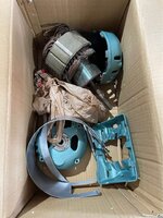
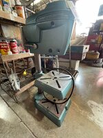
There's a local ad for a drill press with Sears motor, but it's in pieces and I don't want that much of a challenge. In fact I don't even know if it's a Dunlop or a Craftsman DP, but there is indication that the motor might be a Dunlop.

Can you tell from the pics?
 

Attachments

  • cmchallenge1.jpg
    cmchallenge1.jpg
    129.5 KB · Views: 84
  • cmchallenge2.jpg
    cmchallenge2.jpg
    130.9 KB · Views: 80

JoCoSawdust

Well-known member
Joined
Nov 19, 2018
Messages
2,416
Location
Eastern NC
I'm guessing it's a split phase motor from the lack of holes to secure the bottom plate to the base in order to capture the capacitor. Probably a Dunlap or Companion branded 115.
 

JoCoSawdust

Well-known member
Joined
Nov 19, 2018
Messages
2,416
Location
Eastern NC
Great motors Modern Garage. That blue Companion is one of my holy grail motors. Pretty sure it was made by Diehl. I have a 1/2 Diehl motor that also has that mysterious stamping in the border of the data plate.
 

JoCoSawdust

Well-known member
Joined
Nov 19, 2018
Messages
2,416
Location
Eastern NC
Cruzan, about the best image I could get last night. Glad I looked as the Dunlap pictured above is a 44, not a 41 as I originally posted. I've been told that the letter indicates month, the next number the day and the last two numbers the year. Don't know if I believe that or not as "M" is the 13th letter of the alphabet so it doesn't jive. I see a lot of "M"s and a lot of "H"s in this spot. I do think the last two digits of the 115 motors in the space on the data plate indicated year of production. Always up for being proven wrong. IMG_0013.jpg
 
To avoid these ads, REGISTER NOW!

Cruzan80

Well-known member
Joined
Jul 22, 2015
Messages
4,273
Location
Denver, CO
Thanks JoCo. I have also heard the a variation that the month is the first number, and year last two. The letter (IIRC) was shift based?
 

JoCoSawdust

Well-known member
Joined
Nov 19, 2018
Messages
2,416
Location
Eastern NC
This will be the next motor I tear down and hopefully I'll have the discipline to take proper pics. Life is going to have me out of my shop for an extended time so it'll be a while but I wanted to throw this on here.

This is a Diehl-made 1/2hp cap start reversing motor. No date codes on it but I'm guessing mid to late 1930s. The main exterior differences between this and a Packard/Sunlight motor are the curvature of the base where the switches are located and the bearing caps on each end bell. This will be a fun one to do when I have the time.

tempImageCNYy7B.pngtempImageBO2fwM.png
tempImage9rfzq3.pngtempImageemcpUv.png
 

Attachments

  • tempImageP2unIe.png
    tempImageP2unIe.png
    2.3 MB · Views: 65
OP
1

11b30b4

Well-known member
Joined
Jul 16, 2020
Messages
1,029
Location
GA
Wow, you guys have some really cool looking motors. I love the older Craftsman (30s and 40s) motors. Thank you all for sharing.

I finished rebuilding another 115 motor for my 150 drill press. here is a pic of the motor with the sardine can capacitor.

full


And this is that motor assembled.

full


113.19063

full


The 113.19063 is a beast of a motor. This motor is a 1 HP capacitor start, 3450 RPM, 115/230-volt, 60 cycles motor and is reversable with dual shafts. The motor weighs 45.5 pounds and is 13 ¼” to each end of the shaft. The housing is 9 ½” long and 7 ¾” in diameter and the keyed shafts are 5/8”.

full


full


I am not sure about the age of this motor. I suspect it is a mid- 50s motor but the stamping on the data plate says 15A 33. I will look more closely at the capacitor tonight and see if there is a date on it. This motor was attached to my 113.27520 10” table saw. I relaced the cord and powered up the motor to see if it run and it worked perfectly.

full


One of the unique features of this motor aside from its size is the capacitor and where it is housed. In this pic you can see (through all the saw dust) capacitor is housed inside the terminal end frame. Both of the end frames are made from cast iron and the stator band rolled steel about ¼” thick.

full


The base on this motor is removable and previous owner did a fine job of splicing in the toggle switch (not really).

The original bearings for this motor were New Departure 77503 (double shielded). The bearings are 40mm x 11mm with a 17mm bore.

full


I disassembled the motor and placed all the metal parts in simple green for degreasing. I will add some pics as I work on the rebuild.
Working on this motor was a lot of fun and I learned a bit more about motors. Specifically, that for anything around the 1HP range you need a 1HP rated switch. The switch in this motor was only rated for ¾ HP and when I reassembled it, the switch was permanently on. I could move the switch to he off position, but the motor stayed on. This is because the switch was fused in the open connection position and is a common issue with switches not rated for the voltage and amps of a 1 HP motor.

I removed the data plate from the stator band and needed to redrill the panel screw holes.

full


I filled in the old holes with PC-7 and once the stator is painted you will never know anything was done to it.

I reached out to MattBlast to have the data plate reproduced. We worked together to build the graphics and I am very pleased with the final product. Here is a side by side of the new and old data plates.

full


Anyway, here are the parts being primed and painted.

full


full


full


And here is the finished motor:

full


Thanks for the interest.
 
Last edited:
One&Done

New member
Joined
Aug 9, 2021
Messages
1
Just wanted to say thanks to the OP. Your pictures helped me get a motor back together that's been strowed out on a shelf for a while because I didn't document the teardown like I should have.
I couldn't remember for the life of me where all those little washers went on the shafts.

I did make the mistake of removing the sleeve bearings so I could soak the housings in cleaner & when I put it back together, the shaft wouldn't spin. I fought with it for hours before I finally put a wooden dowel in the lathe & turned it down enough to fit inside the bearings with some bearing length pieces of 600 grit sandpaper wrapped around the dowel & glued.

It was a makeshift hone of sorts, I'm not equipped for that sort of problem, but after a little hand lapping with the dowel like I was trying to start a fire, she loosened up nicely lol.

Just throwing that info out there for anyone thinking of breaking one down that far, I'd bypass that step & tape over them like you did. They must have been pressed in at the factory with the housing assembled & then finish honed in place.

Also, I didn't have any trouble with the centrifugal switch on this motor after taking it apart, not sure what we done different but it still works as it should.

This is my first post, love the site & I apologize for being long winded, but I thought maybe some of my experiences with this type of motor could help the next guy.
 

Attachments

  • 20210810_203901.jpg
    20210810_203901.jpg
    251.6 KB · Views: 56
  • 20210810_203846.jpg
    20210810_203846.jpg
    252.6 KB · Views: 64
OP
1

11b30b4

Well-known member
Joined
Jul 16, 2020
Messages
1,029
Location
GA
One&Done, thank you and I am glad you got the bearings sorted out. I had considered removing the pressed in sleeve bearings on one of the 113.19352 motor but the centrifugal switch was giving me such a problem I opted to not mess with the sleeve bearings. For cleaning those end frames I just decided to soak them in simple green and fully degrease the wool in the bearings. This worked and I rinsed the wool out for a long time to make sure I got all the simple green out. Then I soaked them in a mild dish soap water mix to fully clean the wool. Rinse again and then it was paper towels pressed into the shaft bores of the bearings for several days to fully dry them out. I replaced the paper towels several times each day for about a week. Once I was sure the wool was dry, then I masked and painted the end frames. It all worked out but removing the bearings, if it can be done without causing damage would be my choice. I just know I would end up bending something and the sleeve bearings would leak after I tried something like that.

Anyway, thank you for your contribution and great job on that motor rebuild.
 

Nutria

Well-known member
Joined
Jun 23, 2015
Messages
798
Location
Eastern Sierra
The dual shafts sometimes present a problem: an unused shaft can be in a position to wrap up a pants leg. Craftsman made a cover for an unused shaft.
CMan motor shaft cover.jpg

Some of the early motors came with a wood shaft cover that spun on the end of the shaft. Not a complete solution, but at least the keyway is covered. I turned this one from some cherry for a 115.6962 motor on an old Craftsman wood lathe.

IMG_4774.jpeg

I also found a couple of towel rod brackets that work for more exposed situations. This Pinocchio nose is on another 6962 motor on an Atlas bandsaw. As it was a towel rod bracket, it comes complete with a nostril on the bottom.

IMG_4398.jpeg
IMG_4399.jpeg
 
Last edited:
OP
1

11b30b4

Well-known member
Joined
Jul 16, 2020
Messages
1,029
Location
GA
Nutria, I know frank had linked a source for these shaft cover at one time and I will ask him about it. I would like to know of a reasonably price option.


113.12540

full


full


This is another 113 motor that is a Craftsman Emerson 113.12540 ½ HP 1725 RPM capacitor start motor and is thermally protected with a Klixon CEJ69CB switch. It is a ball bearing motor and is reversable. This motor is mounted to my Craftsman 113.24611 Commercial Emerson Gen 4 15.5” Drill Press. Oddly, the dual rotor has different shaft sizes on each end. One end is a non-keyed ½” shaft and the other is a 5/8” keyed shaft. I like this design and it makes the motor usable. The motor weights 21 pounds and comes with a NEMA 56 cradle frame. I forgot to take measurements before I started to rebuild it so I will add them once I finish the rebuild.

full


This motor was likely made in June of 1977 and has the reversing wiring diagram on the data label.

This motor came with two SKF 6203 double shielded ball bearings 40mm x 12mm with 5/8” bore.

full


I made this wiring diagram (sort of) to aid in reassembly once I clean and paint everything. I am guessing most of the novices (like me) would like to see something like this diagram for all of these motors. I will try to get around to making a few more as time goes on. Many of the older motors with fabric shielded lead wires will not be as easy to differentiate the wire colors but I will see what I can do.

full


Anyway, more pics once I finish the rebuild.

Thanks for the interest.
 

TexTJ209

Well-known member
Joined
Feb 16, 2012
Messages
167
Location
Tejas
Tex, I have never seen a cast long C logo on a craftsman motor in the wild ever. That is AWESOME.

I've actually seen a few more attached to tools since I got this one, you start to recognize the big bulbous shape of this particular motor ha. Notice it's actually a Long C Craftsman within a Heritage badge so it's all kinds of weird. Even the capacitor housing is cast, it's a tank!
 

BobbiK

Member
Joined
May 25, 2022
Messages
5
Here's one of my odder motors. 702.199 (possibly 702.1990) made by American Electric Motors, Inc. Heritage era, obviously. :)

Last photo is next to a 40s era more standard motor, it's a big beast.

110193617_10118467951958114_3158219181068511531_n.jpg
111284433_10118467952172684_8581812585791926971_n.jpg
110107427_10118467952432164_7041253285142001199_n.jpg
Hi. I just got done rebuilding this same motor model 702.1991. Painted the body red, bell housings silver metallic, capacitor housing black, and did the long C logo with black letters on a red background. Had to create a terminal block so motor voltage can be switched to 220 v if needed. But I don't know what this motor came off of. Mounting holes are 5" x 3 7/8". 3/4" shaft. I bought it for $20 from a guy parting out an old lathe but he didn't know what the motor came off of. Your motor appears to be on what looks like a Craftsman table saw motor mount. Do you know what the motor came off of?
 

Attachments

  • 20220524_214715.jpg
    20220524_214715.jpg
    295.7 KB · Views: 66
  • 20220524_214658.jpg
    20220524_214658.jpg
    317.2 KB · Views: 59
  • 20220524_203237.jpg
    20220524_203237.jpg
    186.8 KB · Views: 59
  • 20220514_213036.jpg
    20220514_213036.jpg
    242.9 KB · Views: 53
  • 20220524_214721.jpg
    20220524_214721.jpg
    224.2 KB · Views: 70

TexTJ209

Well-known member
Joined
Feb 16, 2012
Messages
167
Location
Tejas
Hi. I just got done rebuilding this same motor model 702.1991. Painted the body red, bell housings silver metallic, capacitor housing black, and did the long C logo with black letters on a red background. Had to create a terminal block so motor voltage can be switched to 220 v if needed. But I don't know what this motor came off of. Mounting holes are 5" x 3 7/8". 3/4" shaft. I bought it for $20 from a guy parting out an old lathe but he didn't know what the motor came off of. Your motor appears to be on what looks like a Craftsman table saw motor mount. Do you know what the motor came off of?

Guy I got it from said it was from a table saw, but no idea what model. The only other one of these I've seen in the wild was under a late 40s Craftsman builder's saw.
 

JEFinCLE

Well-known member
Joined
Nov 21, 2020
Messages
101
Location
Medina Ohio
Timely resurrection of this thread...I am a couple days away from re-assembly of a 1941 Craftsman motor that I haven't been able to find an exact match for on VM. I believe it is this motor from the 1941 catalog:

Motor catalog cut.jpg

Here's the nameplate:


Dm_FFWF3wT-OlHiCfiXDoT4K=w1245-h1660-no?authuser=0.jpg

As best I can see, the model number is 115.8345 -- could be 115.6345, but neither have a manual on VM. It does have the "remote" forward/reverse/off switch as in the catalog listing. I've painted the band with Rustoleum Midnight Blue, which is a very close match to the original. I painted the end bells and base with black wrinkle finish and they came out pretty well.

I would be interested in learning more about how to recreate the nameplate. 11b's always look so perfect.

The motor came off a 1941 floor model 15" drill press with the table/head lift. It is in pretty remarkable shape and should make a great piece if I can force myself to not get in a rush and take shortcuts. I've already created more work for myself by not letting the paint fully cure for a couple days before I removed the masking from the nameplate. I don't "need" this drill press, so maybe I can contain myself.
 
OP
1

11b30b4

Well-known member
Joined
Jul 16, 2020
Messages
1,029
Location
GA
JefinCLe, message MattBlast here on the forum. speak to him first then he will most likely want you to remove the existing badge, flatten it, can it as a PDF or jpg and email it to him. Get some rough measurements as well. When you get the replacement data plate, you can attach it with pop rivets.
 
To avoid these ads, REGISTER NOW!
Top Bottom