To avoid these ads, REGISTER NOW!

Electronic troubleshooting

Snapped-off

Well-known member
Joined
Feb 22, 2012
Messages
4,812
Location
Indiana
Not lighting related but I thought this may be the best place to put this.

UPDATE: A new, working track piece was sourced on ebay. This thread has come to an end. The original chip on board is assumed to be cooked well done.

I'm trying to troubleshoot a toy.
Screenshot_20211129-143102_Chrome.png
There are 4 red switches on the track, and a switch on the spinning tree. When a switch is closed it's supposed to play sounds. Of course there's no sound.

Here's where I'm at so far:
Batteries - good

Battery switch - good, sends 4.5vdc out when closed

Switches - good, continuity on all of them when closed

Wires - good, visual and continuity

Speaker - good

PCB - circuit looks fine overall

Resistors - good

Capacitors - good

Diode - good

Chip on Board - suspect

Here's the PCB:
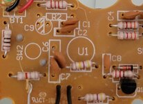
20211129_141836.jpg

I'm determined to get sound out of this thing. Thanks to anyone that can educate.
 
Last edited:
To avoid these ads, REGISTER NOW!

californiaHank

Well-known member
Joined
Nov 20, 2015
Messages
487
Resistors can have 3, 4, 5, or 6 bands.

Three band ones are mainly obsolete - they're 20% tolerance which isn't found much anymore.
For these, the last band is the multiplier and the first two are the first two significant digits, read left to right.

For modern resistors, with 4 or 5 bands -
The last band is the tolerance, for example silver means 10% and gold means 5%
The second from last band is the multiplier, for example black means multiply by 1 and brown means multiply by 10 and red means multiply by 100
The other bands are the significant digits, read left to right.

6 band resistors are special high precision ones - they're like 5 band ones, but have an added band for temperature coefficient.

In some cases. you can't measure a resistor accurately without removing it from the circuit, because other circuit elements that are connected in parallel with the resistor will influence the results.

Modern, low power resistors rarely fail, and when they do, there's usually some obvious sign of failure like cracking or discoloring from overheating.

Small ceramic capacitors, like the ones in your picture don't often fail in low voltage circuits, either.

From your picture, it seems to be an older, simple circuit. I don't know what's on the board outside the picture, but of what I can see, I'd check the voltages on transistor (Q1) in the lower left corner first, and maybe the diode that's mounted above it.
 

APEowner

Well-known member
Joined
Oct 2, 2009
Messages
4,166
Location
Sunny, New Mexico
Resistors almost never go bad without some kind of physical damage and measuring them in circuit is tricky because the rest of the circuit can effect your readings. However, the first two bands are the value, followed by the multiplier. So, brown, black, black is 10 times 1 or 10 ohms. the red, red red is 22 x 100 or 2,200 or 2.2k.

Here's a good calculator Digi-Key calculator

Ceramic caps also rarely fail without some kind of obvious damage although that's more common than a resistor going bad. You really can't test them in circuit for the same reason that you shouldn't test resistors in circuit except more so.

I'd start with a careful look at the bottom of the board under a magnifying glass. You're looking for broken traces and bad solder joints.
 

paulsomlo

Well-known member
Joined
Jul 16, 2013
Messages
3,909
Location
Northern Colorado
I wouldn't bother testing the resistors or the caps - unless they look burnt. The failure rate on passive components is pretty low, especially on ceramic caps. I would start by visually checking for broken solder joints on the backside of that PCB, then checking for broken wires. If you really want to check the caps and resistors, just verify that the resistors are not shorted or open (more likely), and that the caps are not shorted. Then you can look at the diode and transistor.
 
OP
S

Snapped-off

Well-known member
Joined
Feb 22, 2012
Messages
4,812
Location
Indiana
I see where I was going wrong with the multiplier stripe. That all makes sense now.

I'll skip the resistors and capacitors for now.

Should I have 4.5vdc at the transistor? (3 AA) The diode should only be open one way right?

I looked over the circuit and didn't see any breaks or burnt spots but I'll look it over with a magnifying glass. All the soldered joints looked good and felt strong.

The only things not in the picture are where the switch wires are soldered to the pcb. I have continuity on all wires and contact points from the switch to the board, and I've visually checked all the wires. Everything looks fine there.
 
OP
S

Snapped-off

Well-known member
Joined
Feb 22, 2012
Messages
4,812
Location
Indiana
Ok update, it plays music now. I went to check voltage at the transistor and when I touched it, it got audible. I gently wiggled it and now it plays music. I stopped there.

Weak connection at the transistor? Should I resolder it? It doesn't feel loose at all but I can bend it back and forth on the pins.
 

paulsomlo

Well-known member
Joined
Jul 16, 2013
Messages
3,909
Location
Northern Colorado
Ok update, it plays music now. I went to check voltage at the transistor and when I touched it, it got audible. I gently wiggled it and now it plays music. I stopped there.

Weak connection at the transistor? Should I resolder it? It doesn't feel loose at all but I can bend it back and forth on the pins.
Wouldn't hurt to reflow the solder, just don't overdo it and overheat the part. If it's still intermittent after that, there may be a mechanical fault where the leads enter the transistor.
 

californiaHank

Well-known member
Joined
Nov 20, 2015
Messages
487
Ok update, it plays music now. I went to check voltage at the transistor and when I touched it, it got audible. I gently wiggled it and now it plays music. I stopped there.

Weak connection at the transistor? Should I resolder it? It doesn't feel loose at all but I can bend it back and forth on the pins.

I agree with the others who suggest that it's likely a bad solder joint between the transistor lead and the board. You should be able to fix it with a bit of fresh rosin core solder and a bit of heat. As the others have said, use enough heat to allow the solder to flow freely into the joint to make a good mechanical connection, but not so much that you cook the (somewhat heat sensitive) transistor.
 

Metal-Marc

Well-known member
Joined
Aug 31, 2009
Messages
7,248
Location
Foothills of the Adirondacks
If it were me, I'd remove the old solder before flowing new solder so you don't end up with a big solder blob on the board.

Practice a bit on a scrap board if you're not familiar with soldering. Too much heat for too long will cook the transistor or lift the copper trace on the board.
 
OP
S

Snapped-off

Well-known member
Joined
Feb 22, 2012
Messages
4,812
Location
Indiana
If it were me, I'd remove the old solder before flowing new solder so you don't end up with a big solder blob on the board.

Practice a bit on a scrap board if you're not familiar with soldering. Too much heat for too long will cook the transistor or lift the copper trace on the board.
I'm comfortable soldering in general, just have never done it on a pcb. There's already two big blobs on the bottom side, I'll probably **** them off the board and put some new down.
 

Metal-Marc

Well-known member
Joined
Aug 31, 2009
Messages
7,248
Location
Foothills of the Adirondacks
I'm comfortable soldering in general, just have never done it on a pcb. There's already two big blobs on the bottom side, I'll probably **** them off the board and put some new down.

Just in case you've never done it. Put a bit of new solder on the blob, then **** it up right away. The new resin helps to **** the old solder.
 
OP
S

Snapped-off

Well-known member
Joined
Feb 22, 2012
Messages
4,812
Location
Indiana
I agree with the others who suggest that it's likely a bad solder joint between the transistor lead and the board. You should be able to fix it with a bit of fresh rosin core solder and a bit of heat. As the others have said, use enough heat to allow the solder to flow freely into the joint to make a good mechanical connection, but not so much that you cook the (somewhat heat sensitive) transistor.

Just in case you've never done it. Put a bit of new solder on the blob, then **** it up right away. The new resin helps to **** the old solder.
Do you guys recommend I just try reflowing what's there or remove the old and add new?
 
OP
S

Snapped-off

Well-known member
Joined
Feb 22, 2012
Messages
4,812
Location
Indiana
Update #2.

Back home from leave, so I finally got the chance to mess with this.

I'll need a replacement transistor because one of the pins is broken. Is there any way to identify what I need?

Under magnification I can't make out the numbers on the top row but the bottom row has C-E48.

This is basically just a switch to the speaker right? Do I just need to find an E48 4.5v transistor?
 

walta

Well-known member
Joined
Jan 13, 2017
Messages
2,313
Location
Dutzow Missouri
Please post the best photo of the number you can get.

The C and the 48 seem likely to be correct the dash and E seem very unlikely to be correct.


Walta
 
To avoid these ads, REGISTER NOW!

walta

Well-known member
Joined
Jan 13, 2017
Messages
2,313
Location
Dutzow Missouri
I think the top line was the number and the lower line is date and lot # info.

Often the manufacture will try to use the same part wherever possible so the other transistors on the board may be the same type one may be more legible

Walta
 
OP
S

Snapped-off

Well-known member
Joined
Feb 22, 2012
Messages
4,812
Location
Indiana
I think the top line was the number and the lower line is date and lot # info.

Often the manufacture will try to use the same part wherever possible so the other transistors on the board may be the same type one may be more legible

Walta
This is the only transistor on the board unfortunately.
 
OP
S

Snapped-off

Well-known member
Joined
Feb 22, 2012
Messages
4,812
Location
Indiana
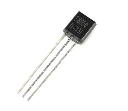
Is it an S8050?

Is there any way to tell what voltages I need? Or do I absolutely need the transistor number?

All the voltages are foreign to me.

This one listed has a base of 5v, which I assume will work with the 4.5v from the batteries. Collector is 30v. Does that mean it can handle up to 30v? Or it needs 30v coming in?
 

californiaHank

Well-known member
Joined
Nov 20, 2015
Messages
487
It's more complicated than that. Voltages on a transistor datasheet are usually maximum voltages for various operating parameters.

My (wild assed) guess is that the transistor was used as an amplifier rather than as a switch, and that the generator of of the 'music' is U1, which is some some sort of IC mounted on the other side of the board (that we can't see). Not knowing more about the circuit it's hard to know what to tell you.

Maybe you will be lucky, and the transistor actually is an S8050, which is typically used as a low power audio amplifier. Is one of the leads from the transistor wired to the speaker and another connected to the battery? If that's true, an S8050 might make sense in that circuit.
 

Max

ALLIANCE MEMBER
Joined
Jun 16, 2018
Messages
3,351
Location
Georgia
Nobody uses a special transistor for a toy like that. It it most likely that a general purpose transistor will work just fine.

The Vbe spec is a maximum, as is the Vce spec. The part you refetenced looks like a good fit to your needs _assuming_ that the original transistor is a NPN. Can you measure the old transistor, or draw a schematic of the circuit?
 
OP
S

Snapped-off

Well-known member
Joined
Feb 22, 2012
Messages
4,812
Location
Indiana
Nobody uses a special transistor for a toy like that. It it most likely that a general purpose transistor will work just fine.

The Vbe spec is a maximum, as is the Vce spec. The part you refetenced looks like a good fit to your needs _assuming_ that the original transistor is a NPN. Can you measure the old transistor, or draw a schematic of the circuit?
What would I need to measure? This is not my area of expertise. I can understand and make sense of most of this stuff after reading it. But it's hard to do any research because I have no idea what I need to look for.
 

Max

ALLIANCE MEMBER
Joined
Jun 16, 2018
Messages
3,351
Location
Georgia
Generally you can use an ohmmeter to measure the BE and BC junctions. One direction will show low resistance and the other high resistance as you are testing the diodes at the junction. Depending on which direction is low resistance you can determine NPN or PNP.

Unfortunately looking at the pics it looks like the leads were cut off of the original transistor. So measuring it is out. And since you don’t know the transistor type for sure, you also don’t know which pins are the emitter, base, or collector either.

The good news is that we can probably figure it out from the schematic. You need to follow the traces from each lead of the transistor and see where they go. One will likely go to a speaker, the other to the plus or minus of the battery, and the other to the IC. There may series or parallel resistors in the oath as well. Can you draw a schematic?
 

californiaHank

Well-known member
Joined
Nov 20, 2015
Messages
487
Yes, trace the circuit.
Where's the speaker connected? Where's the battery connected?

Is one side of the speaker connected to negative power?
Is pin 1 of the transistor connected to the other side of the speaker (probably through a capacitor)?
If that's all true, it's likely an NPN with the same pinout as the S8050, so probably an S8050 would work.
 
Last edited:
OP
S

Snapped-off

Well-known member
Joined
Feb 22, 2012
Messages
4,812
Location
Indiana
Bear with me, I'm working with a phone. I don't think me drawing an electrical schematic would be of use to anyone. I'm a bit slow with this pcb. It's not as common sense to me as pipes and valves.

Yellow - transistor
Cyan - speaker
Red/Black - battery
20211214_120441 (2).jpg

So, I'm assuming the left yellow is the emitter going to the speaker, bottom yellow is the base going to the U1 brain, and the right is the collector which is going to the negative battery connection. But it also jumps down to U1.

Side question: what would U1 be? Would there be a small chip under the black dome?
 

Max

ALLIANCE MEMBER
Joined
Jun 16, 2018
Messages
3,351
Location
Georgia
Yes there is likely a small chip under the black dome. Your guesses for the connections are spot on. Since the collector is going to - it is very likely a NPN. Does the other side of the speaker go to battery plus? If so its a NPN.
 
OP
S

Snapped-off

Well-known member
Joined
Feb 22, 2012
Messages
4,812
Location
Indiana
Does the other side of the speaker go to battery plus? If so its a NPN.
Yes, I guess it ends up there. The left Cyan goes straight down into 2 capacitors (3 vertical connections) that are tied together, and continues down the pcb, which does jump to the battery +.

Just now realizing, is NPN - + - ? And PNP the opposite?
 
OP
S

Snapped-off

Well-known member
Joined
Feb 22, 2012
Messages
4,812
Location
Indiana
There is a good description here: https://www.electronicshub.org/transistor-as-a-switch/

And thinking about it more, you likely have the connections swapped between the emitter and collector. Its been about 20 years since I last designed with BJTs so I am rusty. :)
Isn't the collector the input, and the emitter the output? I have to look it up again.

I guess I was backwards. Emitter is input.

Does it change depending on if it's npn or pnp?
 

Max

ALLIANCE MEMBER
Joined
Jun 16, 2018
Messages
3,351
Location
Georgia
Don’t think of input and output. When the transistor is biased correctly, think of the current into the base (once it’s biased on) controlling the collector to emitter current. The load (a speaker in this case) could be connected to either the collector or emitter.
 
OP
S

Snapped-off

Well-known member
Joined
Feb 22, 2012
Messages
4,812
Location
Indiana
Don’t think of input and output. When the transistor is biased correctly, think of the current into the base (once it’s biased on) controlling the collector to emitter current. The load (a speaker in this case) could be connected to either the collector or emitter.
:eyecrazy: Alright, I guess this is deeper than I'm comprehending.
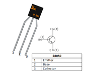
So, say the left yellow is the collector, and the right is the emitter, this is a NPN? I'll go ahead and try the S8050.

Assuming the original is physically the same, the collector was going to the load.
S8050-Pinout.png
 

Max

ALLIANCE MEMBER
Joined
Jun 16, 2018
Messages
3,351
Location
Georgia
You have to look at the schematic symbol. If you note, the arrow is pointing to the outside of the circle - that makes it a NPN. A PNP will point to the inside…
 

californiaHank

Well-known member
Joined
Nov 20, 2015
Messages
487
I also think that some of the discussion has the collector and emittter reversed.
Some transistors in that package style have the C and E leads reversed, so you need to be careful when you're not sure of the part number.

I'm guessing that it's an NPN connected as a common emitter amplifier.

The emitter is connected to the common (negative) battery terminal.
You apply a small input voltage between the base and common and you get a larger output voltage between the collector and common.

The small input signal from the mysterious 'U1' is fed between the base and common (negative).
The larger output signal to the speaker is seen between the collector and common (negative).

So expect ...
Emitter connected to the common negative (with nothing in between).
Collector connected to speaker. Other side of speaker to common negative.
Often there's a cap between the collector and the speaker, but your circuit doesn't seem to have one there.
 
To avoid these ads, REGISTER NOW!
Top Bottom