To avoid these ads, REGISTER NOW!

Electronic troubleshooting

Max

ALLIANCE MEMBER
Joined
Jun 16, 2018
Messages
3,351
Location
Georgia
In circuit resistance tests are iffy. The problem is that other components can be in parallel to the junction you are trying to test and screw up the results. So I would not trust those tests.

I think we’ve got the wrong NPN type, or the collector and emitter are reversed, or both. If you can send me your address privately I can send you some transistors to try. Otherwise I can make a list of the next set of parts to try…
 
To avoid these ads, REGISTER NOW!

FordTruckWench

Well-known member
Joined
Jan 8, 2015
Messages
539
Location
California
I'm not sure it was necessary to have the entire circuit and path out all the switches and the rest of the resistors and caps.

Could you confirm this:

Here's what I see of the relevant part of the circuit:

Start at what is likely the V+ power rail (it goes to a number of other places).
--to--
A resistor of unknown designation and unknown value (one stripe is red, the rest indistinguishable).
--to--
One side of the speaker (black wire).
Other side of the speaker (other black wire).
--to--
An unused circuit board hole/pad.
--to--
One side of the transistor - presumably collector.
Other side of the transistor - presumably emitter.
--to--
Resistor R6 who's value is 47 *10^something (yellow violet, the rest indistinguishable)
--to--
Ending at what is likely the GND power rail (it goes almost everywhere).

And then the base circuit:

From the COB.
--to--
R7 (220 ohm, i.e. red red brown), C8, and the middle pin of the transistor.

The other side of C8 goes to the presumed GND power rail.
The other side of R7 goes to the anode (i.e. unbanded side) of the small diode.
The diode's cathode (i.e banded side) goes to the presumed GND power rail.

----

I cannot figure out the purpose of the diode! The best answer I can come up with is that the diode biases the transistor's base to 0.7 volts. In other words right at the turn on / turn off point. The COB output might be a digital PWM output. C8 would act as a low pass filter turning the digital signal into a variable voltage.
 

FordTruckWench

Well-known member
Joined
Jan 8, 2015
Messages
539
Location
California
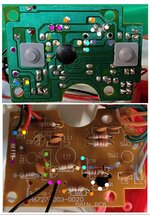
Hey Wrench, I'm not sure if this helps or not. I think this is better than me sketching out a schematic.

I think this confirms what I saw in the previous pictures.

At this point it might be interesting to power up the device, and measure voltage along the current path through the speaker. In particular, the gray dotted resistor, the violet dotted speaker leads, the transistor, and the orange dotted resistor. Measure relative to BT1 (battery?) ground - the blue dot.
 
OP
S

Snapped-off

Well-known member
Joined
Feb 22, 2012
Messages
4,810
Location
Indiana
I think this confirms what I saw in the previous pictures.

At this point it might be interesting to power up the device, and measure voltage along the current path through the speaker. In particular, the gray dotted resistor, the violet dotted speaker leads, the transistor, and the orange dotted resistor. Measure relative to BT1 (battery?) ground - the blue dot.
Yes BT is to the batteries.

I'll get some readings in a bit. I suspect this new transistor is shorted internally. I'm going to remove it from the board and test it properly now that I understand how to test them.
 
OP
S

Snapped-off

Well-known member
Joined
Feb 22, 2012
Messages
4,810
Location
Indiana
So, any updates or doa?
Not yet, waiting on some stuff. Max was kind enough to send me some transistors to try out along with a transistor socket to make testing easier.

I'm pretty sure I cooked the new transistor during installation. I'm going to desolder it today or tomorrow and test it to confirm and I'll update then.

Aside from that, the next update will be next week/whenever the parts show up.
 
OP
S

Snapped-off

Well-known member
Joined
Feb 22, 2012
Messages
4,810
Location
Indiana
Small upgrade to replace the iron I have that's probably older than me. I'd like to find a small case to keep it in.
20211229_130427.jpg
 
  • Like
Reactions: Max

RPH

Well-known member
Joined
Dec 17, 2006
Messages
4,190
Location
Michigan Thumb
You don’t need a case. You need a bench for electronic work. Just another reason for more tools!
 
OP
S

Snapped-off

Well-known member
Joined
Feb 22, 2012
Messages
4,810
Location
Indiana
Update.

The transistor passed the diode test. There's no short present internally. The board however has a short between CE, which I'm not sure is supposed to exist. I don't see any obvious damage between the 2 points.

Also gotta add, this little weller station is incredible compared to the iron i was using. It was up to temp in seconds compared to about a minute for the old non adjustable iron. Removing the transistor from the board was a breeze.

20211231_133925.jpg
 

RPH

Well-known member
Joined
Dec 17, 2006
Messages
4,190
Location
Michigan Thumb
78F0C3BD-FA7C-49C0-9FAB-9FAC75A704DE.jpeg

Clean the solder up around the transistors legs. Both sides. It maybe shorted right there. But keep the hunt on!
Transistor looks like a solder bridge across two legs.
 
Last edited:
OP
S

Snapped-off

Well-known member
Joined
Feb 22, 2012
Messages
4,810
Location
Indiana
78F0C3BD-FA7C-49C0-9FAB-9FAC75A704DE.jpeg

Clean the solder up around the transistors legs. Both sides. It maybe shorted right there. But keep the hunt on!
Transistor looks like a solder bridge across two legs.
Current state is cleaned up. The transistor is off the board and there is a short between CE points on the board.

I definitely had some excess solder there but there was a gap all the way around. Wouldn't the solder have to be physically touching?

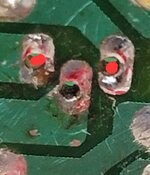
Short across the red points.
20211231_171741.jpg
 
Last edited:

Max

ALLIANCE MEMBER
Joined
Jun 16, 2018
Messages
3,351
Location
Georgia
Just for grins please pull the batteries and test again. How many ohms is the short?
 

FordTruckWench

Well-known member
Joined
Jan 8, 2015
Messages
539
Location
California
Batteries out, still shorted with 39 ohms.

The measurement current is likely running around "backwards", i.e. you are powering up the circuit.

Leave the transistor out, hook the battery up, turn the power switch on. Now measure voltages at the gray dots, the violet dots, the white dots, and the orange dots.
 
To avoid these ads, REGISTER NOW!
OP
S

Snapped-off

Well-known member
Joined
Feb 22, 2012
Messages
4,810
Location
Indiana
The measurement current is likely running around "backwards", i.e. you are powering up the circuit.

Leave the transistor out, hook the battery up, turn the power switch on. Now measure voltages at the gray dots, the violet dots, the white dots, and the orange dots.
Just to clarify, from say orange to orange or battery to orange?
 
OP
S

Snapped-off

Well-known member
Joined
Feb 22, 2012
Messages
4,810
Location
Indiana
From battery negative to each of the points. This will actually result in some duplicate measurements, for example, one of the gray dots and one of the violet dots are the same point in the circuit.
So there's battery voltage at both gray and violet/pink, and at the left white which is presumed to be the collector pad.

Nothing at orange. I guess if there was a short, I should also see voltage present at the emitter (right) and orange?
 

Max

ALLIANCE MEMBER
Joined
Jun 16, 2018
Messages
3,351
Location
Georgia
If there was a short the voltage would be identical. Since it isn’t identical I expect you are seeing the effect of the battery voltage on the ohmmeter.
 
OP
S

Snapped-off

Well-known member
Joined
Feb 22, 2012
Messages
4,810
Location
Indiana
If there was a short the voltage would be identical. Since it isn’t identical I expect you are seeing the effect of the battery voltage on the ohmmeter.
Maybe I need to put the meter down.

I do need to find some more stuff to solder though. This new weller is slick.
 

FordTruckWench

Well-known member
Joined
Jan 8, 2015
Messages
539
Location
California
So there's battery voltage at both gray and violet/pink, and at the left white which is presumed to be the collector pad.

Nothing at orange. I guess if there was a short, I should also see voltage present at the emitter (right) and orange?

The presumed emitter appears to ground via the orange dot resistor. I think the color bands are yellow - violet - gold - gold, i.e. 4.7 ohms 5%. In other words, a very low resistance. If there were a short between the emitter and collector pads, you wouldn't see battery voltage on the collector pad.

Two more tests (both with battery attached on turned on):

1) Jumper across the emitter and collector pads. You should hear the speaker click as you apply and remove the jumper.

2) Measure the voltage on the base pad (relative to battery ground.) Measure both DC and AC. Press the buttons to make the toy play sound. Measure the voltage again while the toy is supposed to be playing sound.
 
OP
S

Snapped-off

Well-known member
Joined
Feb 22, 2012
Messages
4,810
Location
Indiana
Two more tests (both with battery attached on turned on):

1) Jumper across the emitter and collector pads. You should hear the speaker click as you apply and remove the jumper.

2) Measure the voltage on the base pad (relative to battery ground.) Measure both DC and AC. Press the buttons to make the toy play sound. Measure the voltage again while the toy is supposed to be playing sound.
Nothing from CE. There's only static if the base and collector are shorted which I've been avoiding.

Readings are negligible. Ranging from
10-16mV. Nothing changes when closing any of the switches.
 

FordTruckWench

Well-known member
Joined
Jan 8, 2015
Messages
539
Location
California
Nothing from CE. There's only static if the base and collector are shorted which I've been avoiding.

Nothing at all when you jumper C to E? I'd expect a single click from the speaker when you touch the jumper, and another click when you pull the jumper away. If you can physically look at the speaker, you should be able to see the cone move in or out.

Hmmm. So a new test:

Put your meter in current (amps) mode. WARNING: A meter in current mode is dangerous! It works by essentially being a short. If you leave it in current mode, forget, and pick it up at some future time expecting to measure voltage, then you can blow up stuff!

Hook the meter up across the transistor's C and E pads, i.e. between the violet-to-white trace, and the white-to-orange trace. And oh, have the battery hooked up and turned on for the toy. Probing this way, the meter should show the current going through the speaker. Don't expect a high current, but there should be some non-zero current.

I'm wondering if R6 was knocked loose in the same calamity that damaged the transistor...
 
OP
S

Snapped-off

Well-known member
Joined
Feb 22, 2012
Messages
4,810
Location
Indiana
Nothing at all when you jumper C to E? I'd expect a single click from the speaker when you touch the jumper, and another click when you pull the jumper away. If you can physically look at the speaker, you should be able to see the cone move in or out.

Hmmm. So a new test:

Put your meter in current (amps) mode. WARNING: A meter in current mode is dangerous! It works by essentially being a short. If you leave it in current mode, forget, and pick it up at some future time expecting to measure voltage, then you can blow up stuff!

Hook the meter up across the transistor's C and E pads, i.e. between the violet-to-white trace, and the white-to-orange trace. And oh, have the battery hooked up and turned on for the toy. Probing this way, the meter should show the current going through the speaker. Don't expect a high current, but there should be some non-zero current.

I'm wondering if R6 was knocked loose in the same calamity that damaged the transistor...
Getting 130 mADC from CE, and the speaker is giving some static.
 

FordTruckWench

Well-known member
Joined
Jan 8, 2015
Messages
539
Location
California
Getting 130 mADC from CE, and the speaker is giving some static.

Good!

Just curious, what's the battery voltage? I'm suspecting 3 volts (two AA or AAA cells.)

I think the next step is to solder in a socket, and then install an NPN transistor in the socket (with the E closest to where the board is labeled Q1, and the B in the middle position.)
 
OP
S

Snapped-off

Well-known member
Joined
Feb 22, 2012
Messages
4,810
Location
Indiana
Good!

Just curious, what's the battery voltage? I'm suspecting 3 volts (two AA or AAA cells.)

I think the next step is to solder in a socket, and then install an NPN transistor in the socket (with the E closest to where the board is labeled Q1, and the B in the middle position.)
4.5v, 3 AA

That's the plan. Should have a care package in a couple days.

:beer:
 

RPH

Well-known member
Joined
Dec 17, 2006
Messages
4,190
Location
Michigan Thumb
I did plenty repairs to board problems when I worked. Some repairs were not economically viable but I would get on the trail. It was hard to stop as you will deem it to work. Also one learns a lot about the circuits operation. Stay on it. The satisfaction of fixing it will be worth it.
 
Last edited:

RPH

Well-known member
Joined
Dec 17, 2006
Messages
4,190
Location
Michigan Thumb
Great, I figured the next episode of “How the Electrons Flow” was due. Have fun and get it working. Then tell us what you found.
 
OP
S

Snapped-off

Well-known member
Joined
Feb 22, 2012
Messages
4,810
Location
Indiana
Great, I figured the next episode of “How the Electrons Flow” was due. Have fun and get it working. Then tell us what you found.
I think we need either a new scriptwriter or a new main character.

The transistor socket leads are too big for the board holes. I was really looking forward to trying them.

I had 3 different NPNs to try out, and none of them worked. 2 PNPs but i haven't tried them since we know the original is a NPN.

I will say my soldering/desoldering skill has vastly improved.

This show may be headed for the chopping block. :Help:

I'm going to do another visual once over of all the wires and components.
 

RPH

Well-known member
Joined
Dec 17, 2006
Messages
4,190
Location
Michigan Thumb
Get a small drill and enlarge the hole. Most likely solder is in it. Always kept small drills available. Wrap it tape if you don’t have a holder. It’s only solder! Stay with it though, look at what you learned.
 
To avoid these ads, REGISTER NOW!
Top Bottom