To avoid these ads, REGISTER NOW!

Electrical motor help (yes, I've searched)

American Locomotive

Well-known member
Joined
Jan 8, 2017
Messages
11,014
Location
Rhode Island
I'm going to be honest Zeke, none of us understand at all what you're doing. You're all over the place, and everything you are saying is full of contradictions.
Looking at the diagram I figured it should to to the new 2,3,4 (since 2 and 4 were already a pair) and that's where it should go. Well that turned out the lights, my first direct short.
You said 2 and 3 were a pair, not 2 and 4. Why are you tying wires 2, 3 and 4 together? I did not say to tie wires 2, 3 and 4 together. That will result in bypassing one of the windings.
And by moving wires as diagramed, I ended up with presumably a wire from switch terminals 1 or 2 with no home.
If you followed what I showed EXACTLY, there is no possible way to end up with a wire without a home.
So I give up. I can't do this. I'll hire it out. Best thing I can do is take the motor switch with conduit and all to the shop. Then I'll bring it back as complete assembly and bolt it back on. Thanks to all.
This is not hard. The problem is you're making it way harder than it needs to be by not paying attention to the details and keeping track of what's going on.

Here is a re-drawn diagram of what YOU provided us. You said this diagram allowed the motor to work, albeit with reduced power. Remember, we're IGNORING any and everything to do with the switch connections at this point.
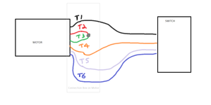
240v.png

Here are the changes you SHOULD have to make to allow for 120v operation. Whatever wire originally attached to T1 at the motor still connects to T1 at the motor. The T2 wire is just joining it. Whatever wire still originally went to the T4 wire is still connected to it. T3 is just joining it. Everything else stays the same! As you can see, there is no possible way you could have ended up with an extra wire with no where to go.
120v.png

Now it's entirely possible my revised diagram above is not correct for 120v operation. However since you keep ending up with the wrong wires connected together and extra wires floating around - I do not believe you are connecting the motor as shown.
 
Last edited:
To avoid these ads, REGISTER NOW!

dogdog

Well-known member
Joined
Nov 15, 2011
Messages
12,711
The cap voltage rating is the operating voltage of that cap... you mentioned it earlier already, the run coil don't see more than 120V.. when in high voltage mode... the W1 is in series with W2, supposedly it will act as voltage dropper.. so 1/2 of 240 is 120. that the run coil sees and the cap sees. me. if I have to buy a new cap, I'll get one that is 300V rated... but old cap 110V would still works works. Don't trust me though, I have not touch those stuff in ages.


KVL still applies to inductor as well as resistors I think...


I would verify your current hook up first if it is me... W1 W2 W3 and make sure W1 and W2 is in series ( high voltage setup) before trying...
you cap still can go kaboom (well a pop and some bad smell of that carcinogen liquid pcb) if it happens your W1 and W2 are parallel... your Run coil will also be in parallel, and Cap probably sees 240V-ish... that is a scenario you would try to avoid...

Nope never done it, so can't say ya / nay.

You keep saying 2 caps. I know about 2 caps on HVAC, mostly dual. I have one large old cap outside the motor like a lot of old motors. I can pretty well say by reading that it's a start cap.

Dual Cap capacitor are just two capacitor build into one and shares a common end. Nothing to do with old caps that have questionable liquids inside as dielectric, pcb was used in the old days... especially older motors... it might not be the case, but you do have a 1944 motor according to you.

PCBs (polychlorinated biphenyls)

PCBs as in this https://www.riverkeeper.org/campaigns/stop-polluters/pcbs/


?
where did you see me saying two caps. I said if you blow it up (in a specific scenario you can when applying 240v to it, normal case you won't), worse case is you buy a new one, and I would get a higher volt rated instead. The worse case scenario.

The link is for KVL (Kirchhoff's Voltage Law )... other than ohm's law in electrical-ma-stuffs. Inductors can function as voltage dividers in a circuit..

I was hoping you would read through that post in practicalmachinist site (there is another post with better 120v and 240v configuration drawings), this diagram (the 120V configuration, the low voltage setup) and identify your W1 and W2 and W3 then get it configured like this diagram from that practical machinist post. Understand how these winding works really helps you in troubleshooting. Otherwise it's just probing with a device.

Aeito.png
 
Last edited:
OP
Z

Zeke

Well-known member
Joined
Aug 13, 2009
Messages
17,176
Location
Long Beach CA, the sewer by the sea.
Look guys every wire had a connection — it was one on one in the shown 240v configuration. What did I do? I disconnected 2 & 3 as directed. Wire #2 needed to got to #1. Fine, #1 comes out of the motor, tuck that away. Note: #1 was connected to terminal 1 (let's call that S1) No one said to include the wire from S2 to #1. You said concentrate on the motor, not the switch. That was mentioned in two contexts: one, bench the the motor with no switch and two, it was mentioned the switch was wired fine, just make the swaps. So I left the connection to S1 out of the connection. Follow me so far? NO one said to make a 3 wire connection, just connect 1 to 2 on the motor. Done.

So then there's #3 sitting there looking for a home. You say connect to 4 on the motor, which in the 240v scheme was connected to the middle lug on the switch (S4) making it hot in one direction and connected to the 120v neutral side in the other position. That is evident showing the red lines.

I'm showing how it was wired when it ran in both directions but started surging under load. And for good measure I'm showing the switch wiring diagram and trying to use the marked schematic as a guide.

You can call me stupid, you can say I'm making conflicting statements, I don't care. I followed advice to the letter. I may have goofed up a couple of times, but eventually I did what was suggested.

In conclusion, the suggestion to undo 2,3 and make both 1,2 and 3,4 pigtails, left a wire out given the directions to make these changes. Actually it wasn't clear what to do with T-4 from S4 either.


100_0403[1].JPG100_0404[1].JPG284698-05e5d5c5735bb47e158438f064cb8b1a.jpg100_0403[1].JPG100_0404[1].JPG
 

dogdog

Well-known member
Joined
Nov 15, 2011
Messages
12,711
It's hard to diag and trouble shoot over the web... but I would be interested in the result what was the fix.. corroions/ break in wires, leaky insulation or just mis-configurations.
 

Bert_

Well-known member
Joined
Dec 24, 2016
Messages
9,776
Location
NW Iowa
I've never heard anyone mention the word stupid. I think we are all just getting frustrated because there is a lack of clear communication. I'm not always sure what connections you are trying.

I think the problem is that what might be very obvious to someone who works on motors often is not very obvious to someone that is new to it.

If you try one of the connection methods posted here just be clear about exactly how you wired it and describe what the result was. Draw a diagram if it helps, this stuff is not always clear when described with words.
 

Bert_

Well-known member
Joined
Dec 24, 2016
Messages
9,776
Location
NW Iowa
Current we know that this connection makes the motor run. It surges and doesn't have much power, which makes me think it's wired for high voltage.KIMG1620.JPG

So based on that and the ohm readings you gave us a while back I think the picture below must be the correct connection for low voltage.KIMG1621.JPG

If any part of my post doesn't make sense please tell me so we can both understand what's going on. I labeled each connection at the motor with a letter. Each letter represents a wire nut connection.
 
Last edited:

American Locomotive

Well-known member
Joined
Jan 8, 2017
Messages
11,014
Location
Rhode Island
You can call me stupid, you can say I'm making conflicting statements, I don't care. I followed advice to the letter. I may have goofed up a couple of times, but eventually I did what was suggested.
No one called you stupid. But you need to be more clear on what you've done, because it's leaving us confused. In our diagrams, we're drawing a 3 way junction.
new.jpg
You can see at that junction point, three wires need to come together. T2, T1 and the wire coming from the switch that originally went to T1. When you see that little circle, it means every wire intersecting that circle is connected together at that point.

Bert's diagrams below show it even more clearly.

Current we know that this connection makes the motor run. It surges and doesn't have much power, which makes me think it's wired for high voltage.View attachment 1616495

So based on that and the ohm readings you gave us a while back I think the picture below must be the correct connection for low voltage.View attachment 1616496

If any part of my post doesn't make sense please tell me so we can both understand what's going on.
 
OP
Z

Zeke

Well-known member
Joined
Aug 13, 2009
Messages
17,176
Location
Long Beach CA, the sewer by the sea.
Well, one thing I see right off the bat is a 4-wire configuration. Let me look at my switch again and see what I've got. I can't see a thing wrong with (Bert's) diagram above. It jives with how the switch works. Forward rotation (CW) would make T-1 and T-2 hot returning neutral through t-3 and T-4. Reverse would make T-4 and T-3 hot returning neutral current through T-1 and T-2 as then they would be switched to T-5 and the jumper. I know it's AC we're dealing with, and the only difference I had was L-1 and L-2 were hot/neutral respectively. And because T-6 is tied to a constant hot regardless of F or R position, it always returns current via T-5 and the jumper.

With T-2,T-3 wired together, it would definitely seem that I had the coils in series. What that means to me at this point is that I'm (OK, not stupid) but ignorant of high and lower voltage schematics.

Gentlemen, I'll give her another go before I head out to the motor shop. They quoted me a $40 diagnosis charge which might be worth the time and money if I fail again.
 

FredWanaker

Well-known member
Joined
Mar 27, 2021
Messages
1,470
Location
NorCal
Zeke. my suggestion is put the switch down until you know the wiring that makes the motor runs right. Just put it out of your head for now. You don't put the roof on or the windows in to pour the foundation.

What would really help me, and I think some other people here too. Can you clearly confirm what you wrote earlier

1. There are six wires, T1, T2, T3, T4, T5, T6 coming out of the motor and they are not connected to each other as far as you can see.

with the ohm meter -

2. That the resistance between T1 and T3 is about 2.7 ohms

3. That the resistance between T2 and T4 is about 2.4 ohms

4. That T3 and T6 showed continuity that went away as the cap charged. It should also go away if you open the centrifugal switch.

5. That T5 shows never shows continuity to anything even the motor case ground. However if it does show continuity to something, what?

6. That you have been working with 120V only and not 240V
 
OP
Z

Zeke

Well-known member
Joined
Aug 13, 2009
Messages
17,176
Location
Long Beach CA, the sewer by the sea.
Fred, that is 100 % affirmative. IDK why you want me to not use the switch. I'm not going to know if R works, or vice versa. Your own drawing shows the current path changing. I've connected the motor on the bench several ways and ether got a hum or nothing. I would need a new schematic telling me what wire to leave capped off so that I'm only dealing with one rotation.

American, you said "You can see at that junction point, three wires need to come together. T2, T1 and the wire coming from the switch that originally went to T1. When you see that little circle, it means every wire intersecting that circle is connected together at that point." It would have been helpful if you drew the original wire back into the drawing. I didn't go to school and study EE. I don't read electrical schematics with omissions in mind even if they are obvious to you.
 
To avoid these ads, REGISTER NOW!

FredWanaker

Well-known member
Joined
Mar 27, 2021
Messages
1,470
Location
NorCal
Zeke. The reason you want to get the motor running right in one direction on its own is to make it easy to get the switch right. You lost where the wires went when you moved it or the prior guy screwed up. None of the diagrams provided made it work right. So you start over with just the motor and the six wires. Once it works right then you easily add reverse and then the switch. Answer this - where does T5 go? It is a wire. It has a marking, where does it go? It isn't just out there doing nothing. Where does it go?
 

American Locomotive

Well-known member
Joined
Jan 8, 2017
Messages
11,014
Location
Rhode Island
Zeke. The reason you want to get the motor running right is to make it easy to get the switch right. You lost where the wires went. None of the diagrams provided made it work right. So you start over with just the motor. Once it works right then you easily add the switch. Answer this - where does T5 go? It is a wire. It has a marking, where does it go? It isn't just out there doing nothing. Where does it go?
He found the original diagram, and got the motor working right. It starts up and goes both ways. It's just configured for the wrong voltage.
Fred, that is 100 % affirmative. IDK why you want me to not use the switch. I'm not going to know if R works, or vice versa. Your own drawing shows the current path changing. I've connected the motor on the bench several ways and ether got a hum or nothing. I would need a new schematic telling me what wire to leave capped off so that I'm only dealing with one rotation.
I'm going to say you have the switch connected correctly. It starts the motor, it makes it go either direction. So the switch can be left alone. When we look at your wiring diagram that you had, it makes sense. Another important thing to remember is that there isn't a "clockwise" wire and a "counter clockwise" wire. You actually need all the wires hooked up to just go one direction only.

Imagine if the start coil and the run coil in the motor each have an "A" side and a "B" side. Putting "hot" to both A-sides, and "Neutral" to both B-sides will make the motor spin one way. Putting "Hot" to the A-side of the start winding, and "Hot" to the B-side of the run winding, will cause the motor to spin the other way. What your switch is doing, is flipping the connections around to one of the windings. Basically, if both windings are "going the same direction", the motor will spin one way. If the start and run windings are going "opposite" each other, the motor will spin the other way.

So there will never be any capped off wires. The motor always needs all of the wires connected to work.
American, you said "You can see at that junction point, three wires need to come together. T2, T1 and the wire coming from the switch that originally went to T1. When you see that little circle, it means every wire intersecting that circle is connected together at that point." It would have been helpful if you drew the original wire back into the drawing. I didn't go to school and study EE. I don't read electrical schematics with omissions in mind even if they are obvious to you.
I'm not an EE either. But look at my schematics - I didn't omit the original wire - It's still there in the drawing!
100_0402[1].JPG

We're all trying to help you, but there seems to be some disconnect between the information we're presenting you, and how you're interpreting it. Perhaps we made some assumptions about your knowledge of electrical schematics. But it's important we all get on the same page about standard electrical schematic notation. If you see a wire intersect another wire with a circle - that means each wire you see there needs to be joined together. What can we do to make the diagrams more clear?
 
OP
Z

Zeke

Well-known member
Joined
Aug 13, 2009
Messages
17,176
Location
Long Beach CA, the sewer by the sea.
We're fine.
Zeke. The reason you want to get the motor running right in one direction on its own is to make it easy to get the switch right. You lost where the wires went when you moved it or the prior guy screwed up. None of the diagrams provided made it work right. So you start over with just the motor and the six wires. Once it works right then you easily add reverse and then the switch. Answer this - where does T5 go? It is a wire. It has a marking, where does it go? It isn't just out there doing nothing. Where does it go?
T-5 is connected to what I now refer to as S3 in order to not confuse the ID's of wires labeled originating from the motor and wires of the same number coming from the switch. My mistake in interpreting is that I wasn't differentiating the "T" wires from wires coming from the switch terminals. So when someone say connect a and b, I connected a and b only with no regard to what a or b was initially connected to.

---------------------------------------------------------------------------------------------------------------------

Frankly, I'm beginning to understand this. I have had zero experience with motors other than being able to follow simple schematics typically found on a label somewhere on a motor. Things like "switch 5 and 8 to change rotation direction," or do "such and such" to go from 240v to 120. Never have I seen a drum switch before and this motor has no schematics. After reading on other forums about South Bend wiring, it seems that GE and SB never did provide that information. It's given SB owners the fits all along. This is partly due to the fact that this was made during WWII and parts were used at random as they became available. So there are a dozen iterations of these and major confusion occurs even amongst SB owners because it's a bit rare that any 2 people are actually comparing identical machines.

Therefore, there are a lot of people who convert to a DC motor with VFD. They do this to drill presses a lot as well. Depending on the source and age of a DC motor with a VFD, it can result in inconsistent torque. I believe I read that if you spend enough money to buy a quality set up (and not something from an ancient treadmill) that you will get even torque throughout the motor's recommended range. It's not cheap.

But, I digress. Anyway, I have always thought what Steven Stills wrote when he said, "Love the one you're with." And if you have 5 RPM ranges due to the cone pulleys, why mess with that? Only the best machinists know he exact rate of cut expressed as inches per minute vs. RPM. I'll be very happy if I get this thing to run and start making chips. If I find that I need something more sophisticated later on, I'll deal with that in the future.
 

FredWanaker

Well-known member
Joined
Mar 27, 2021
Messages
1,470
Location
NorCal
Zeke - Ok, I guess I was confused because you wrote when you measured the wires early on:

1-5=0
2-5=0
3-5=0
4-5=0
6-5=0

where 0 equals infinity.

When the motor by itself runs correctly at the correct speed and doesn't surge, I'd like to know what that wiring is for each direction. Figuring out the switch should be easy then.
 
OP
Z

Zeke

Well-known member
Joined
Aug 13, 2009
Messages
17,176
Location
Long Beach CA, the sewer by the sea.
Well, hallefrickenlujah. What can I say but my sincere and humble thanks.

No more to see here, so we move on. When I get a few things cleaned up, buttoned up and sorted, I'll share a pic of OUR pride and joy. You all deserve much more than I have to offer. This thread has to be a classic for 2022.

Thank you.
 

dogdog

Well-known member
Joined
Nov 15, 2011
Messages
12,711
dogdog, why else would I be rejoicing?:giggle: Clearly we don't quite understand each other's subtleties.:sick:
You helped me out a ton along with Bert and American
It’s hard to explain. At this point I am just curious about the cause and fix. The Sherlock in me gave up. The Holmes in me still curious lol. Communication is not my strong suite.

good to know, I am still clueless about the fix.
 
OP
Z

Zeke

Well-known member
Joined
Aug 13, 2009
Messages
17,176
Location
Long Beach CA, the sewer by the sea.
It’s hard to explain. At this point I am just curious about the cause and fix. The Sherlock in me gave up. The Holmes in me still curious lol. Communication is not my strong suite.

good to know, I am still clueless about the fix.
Well, it was pretty simple. I followed your T-1,2 and T-3,4 connection advice but I added back the hot and neutral that I had wired into the switch box to save space in the motor box which is close to 2" x 2 x 1.75. IOW, not a lot of room for conventional wire nuts, even the slimmest ones. Turns out that the wires from the box make the circuit (Of course they do).

So, it was T-1,2+S1 and T-3,4+S4 that did it. T-5,6 run through the switch and the circuit is the same polarity in either F or R. For clarification, I'm calling polarity the same as wiring a table lamp. You want hot leg to the base of the socket and the neutral to the socket threads. the start winding does not connect but one way in the switch. IDT it matters if 5,6 are reversed in the switch box. But don't quote me on that and I'm not going to fool with it.

When the polarity is reversed on the run windings, the motor turns the other way. Now if we start talking about magnetic fields and polarization, I have to duck out 'cause I know nothing. I know a little more than I did, actually. I think it was you that said it's not hard, read the diagram. But for a while I was trying to peel an apple with a popsicle stick.

BTW, I like your S and H metaphor.

For me, this has been an epic thread. I have 50,000}+ posts spread out but I'll never forget this.
 
To avoid these ads, REGISTER NOW!
Top Bottom