
American Locomotive
Well-known member
I'm going to be honest Zeke, none of us understand at all what you're doing. You're all over the place, and everything you are saying is full of contradictions.
Here is a re-drawn diagram of what YOU provided us. You said this diagram allowed the motor to work, albeit with reduced power. Remember, we're IGNORING any and everything to do with the switch connections at this point.
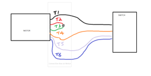
Here are the changes you SHOULD have to make to allow for 120v operation. Whatever wire originally attached to T1 at the motor still connects to T1 at the motor. The T2 wire is just joining it. Whatever wire still originally went to the T4 wire is still connected to it. T3 is just joining it. Everything else stays the same! As you can see, there is no possible way you could have ended up with an extra wire with no where to go.

Now it's entirely possible my revised diagram above is not correct for 120v operation. However since you keep ending up with the wrong wires connected together and extra wires floating around - I do not believe you are connecting the motor as shown.
You said 2 and 3 were a pair, not 2 and 4. Why are you tying wires 2, 3 and 4 together? I did not say to tie wires 2, 3 and 4 together. That will result in bypassing one of the windings.Looking at the diagram I figured it should to to the new 2,3,4 (since 2 and 4 were already a pair) and that's where it should go. Well that turned out the lights, my first direct short.
If you followed what I showed EXACTLY, there is no possible way to end up with a wire without a home.And by moving wires as diagramed, I ended up with presumably a wire from switch terminals 1 or 2 with no home.
This is not hard. The problem is you're making it way harder than it needs to be by not paying attention to the details and keeping track of what's going on.So I give up. I can't do this. I'll hire it out. Best thing I can do is take the motor switch with conduit and all to the shop. Then I'll bring it back as complete assembly and bolt it back on. Thanks to all.
Here is a re-drawn diagram of what YOU provided us. You said this diagram allowed the motor to work, albeit with reduced power. Remember, we're IGNORING any and everything to do with the switch connections at this point.
Here are the changes you SHOULD have to make to allow for 120v operation. Whatever wire originally attached to T1 at the motor still connects to T1 at the motor. The T2 wire is just joining it. Whatever wire still originally went to the T4 wire is still connected to it. T3 is just joining it. Everything else stays the same! As you can see, there is no possible way you could have ended up with an extra wire with no where to go.
Now it's entirely possible my revised diagram above is not correct for 120v operation. However since you keep ending up with the wrong wires connected together and extra wires floating around - I do not believe you are connecting the motor as shown.
Last edited:

![100_0403[1].JPG](https://www.garagejournal.com/forum/data/attachments/1462/1462717-e7f282680272d8dd45f98b2943e773f9.jpg "100_0403[1].JPG")
![100_0404[1].JPG](https://www.garagejournal.com/forum/data/attachments/1462/1462718-fde46982c93a6c18cd8b10d5c0a569f7.jpg "100_0404[1].JPG")
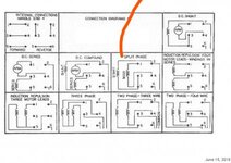


![100_0402[1].JPG](https://www.garagejournal.com/forum/data/attachments/1463/1463102-6a33d5c3d687fa92e3f4d9ddc563add9.jpg "100_0402[1].JPG")
 Clearly we don't quite understand each other's subtleties.