To avoid these ads, REGISTER NOW!

What's wrong with my old Craftsman grinder?

agent max

Member
Joined
Aug 5, 2022
Messages
12
Location
Tennessee
I have this older Craftsman variable speed bench grinder, and recently it stopped working. Specifically, when I turn the switch on, nothing happens. I took it apart and tested:
  • the capacitors on the control board,
  • the starting capacitor,
  • the diodes,
  • the potentiometer for the speed control,
  • and the switch.
Sure enough, three of the capacitors were bad. I ordered higher-amperage replacements from Mouser Electronics, removed the old ones, and soldered the new ones in. Everything else seemed to be fine.

So I went ahead and tested it, and nothing happened. Went off to Google and found a thread on this exact forum about a similar issue, and one reply suggested the problem could be a bad triac. Ordered a replacement BTA12-600B from Mouser, as well as a BTA16-600B just in case the problem was a low amperage rating on the triac.

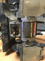
Installed the new triac- the 16-amp one- and still nothing happened. Well, now I'm stuck. I'd rather not buy a new one because I'm short on funds right now, and I hate throwing stuff away if there's a chance I can fix it. If anyone has any ideas, throw 'em out there, no matter how stupid. Photos are attached (hopefully).

"Turn it off and back on again" and "Is it plugged in" don't count. :p
 

Attachments

  • 35E0BEB6-6EA3-4DF9-83B5-B88E1CF1B3AF.jpeg
    35E0BEB6-6EA3-4DF9-83B5-B88E1CF1B3AF.jpeg
    337.1 KB · Views: 61
  • 0A70D3EB-3902-4931-A4C0-43B2B808BA47.jpeg
    0A70D3EB-3902-4931-A4C0-43B2B808BA47.jpeg
    306.4 KB · Views: 63
  • F803287C-14A8-4814-9970-8C5F31281FA2.jpeg
    F803287C-14A8-4814-9970-8C5F31281FA2.jpeg
    308.8 KB · Views: 58
  • 335876D6-EB77-4562-8A5C-B21B5D25DBEC.jpeg
    335876D6-EB77-4562-8A5C-B21B5D25DBEC.jpeg
    312.9 KB · Views: 61
  • 6149D917-16D1-4A63-B91C-11E3855966EB.jpeg
    6149D917-16D1-4A63-B91C-11E3855966EB.jpeg
    328.5 KB · Views: 64
To avoid these ads, REGISTER NOW!

tool_scrounge

Well-known member
Joined
Jul 20, 2010
Messages
4,176
Location
Southern California
Hmm.. If that link to the other post is correct, this is a brush DC motor. One option might be to swap the drive board for an industrial DC motor drive, such as the Minarik drives in the ebay listings below:


But if you go that route is would be nice to know more about the motor.
 

tool_scrounge

Well-known member
Joined
Jul 20, 2010
Messages
4,176
Location
Southern California
The label lists in wall current at 2A at 120V. I was not sure what if the motor current is the same. On some DC motor drives I have seen, the listed AC input current to the motor drive can be higher than the max motor current. For example, the first Minarik motor amp listed above uses 3A input for a max current of 1.5A to the motor stator and 0.5A to the motor field (if the motor has one). If there are only 2 wires running to the motor, there is no field winding. The max motor currents are potentiometer adjustable on the driver board.
 

dogdog

Well-known member
Joined
Nov 15, 2011
Messages
12,711
1) it might be an universal brushed motor, so check the brushes make sure they are still good, check the “commutator ?” For carbon tracks, clean the grooves without destroying any wires. Similar to your vacuum motor. The ac ones.

2) you see there is a capacitor. Normally ac universal motor doesn’t need capacitor like ac induction motors. So you mentioned 3 caps? Is it there as a voltage dropper? Or just a ripple smoothing

3) you have ac input there? Carefully measure the input ac voltage and compare to the ac output ? At max? Usually if it is a triac type output ac output are not clipped at max. If you have oscilloscope it would be easier to see. Multimeter ac mode you should see average or peak. I think.
 
To avoid these ads, REGISTER NOW!
OP
A

agent max

Member
Joined
Aug 5, 2022
Messages
12
Location
Tennessee
1) it might be an universal brushed motor, so check the brushes make sure they are still good, check the “commutator ?” For carbon tracks, clean the grooves without destroying any wires. Similar to your vacuum motor. The ac ones.

2) you see there is a capacitor. Normally ac universal motor doesn’t need capacitor like ac induction motors. So you mentioned 3 caps? Is it there as a voltage dropper? Or just a ripple smoothing

3) you have ac input there? Carefully measure the input ac voltage and compare to the ac output ? At max? Usually if it is a triac type output ac output are not clipped at max. If you have oscilloscope it would be easier to see. Multimeter ac mode you should see average or peak. I think.
1: I'm not sure what you mean by "universal brushed motor." I do know that it's a DC motor, that's what the board is for- pulsing the AC from the wall into DC that the motor can use.

2: Yes, the big capacitor is the start capacitor. I think those are pretty common with large DC motors. I'm not sure what the other capacitors are for, probably part of the AC-DC circuit.

3: The grinder plugs into the wall, if that's what you mean. How would I measure the output AC voltage?
 

dogdog

Well-known member
Joined
Nov 15, 2011
Messages
12,711
1: I'm not sure what you mean by "universal brushed motor." I do know that it's a DC motor, that's what the board is for- pulsing the AC from the wall into DC that the motor can use.

2: Yes, the big capacitor is the start capacitor. I think those are pretty common with large DC motors. I'm not sure what the other capacitors are for, probably part of the AC-DC circuit.

3: The grinder plugs into the wall, if that's what you mean. How would I measure the output AC voltage?

why do you think this is a DC motor? is it because it have a brush? go look at your corded ac grinder... it also have brush, does that mean it's DC motor.... is there another large bridge rectifier that wasn't show after the board output?

what kind of dc motor uses a start capacitor? Large DC motor? that is new to me. Never seen one. in PMDC or non PMDC motors.
measure the voltage carefully since you are dealing with AC. I don't know how to advise you to check and measure those if you don't know.
in few of your pictures, you have input and output in that circuit board.

anyways, since you mentioned that you have took out few components and messing with it, your best bet it to verify that the board still works and that is to verify the output voltage of that controller, ideally you should be measuring the output with an oscilloscope to verify that it is clipped properly... you do know a triac output clipped AC right ? another word in other part of the world is called Phase fired controller (I think)... not A DC converter? Dunno.
 
OP
A

agent max

Member
Joined
Aug 5, 2022
Messages
12
Location
Tennessee
what kind of dc motor uses a start capacitor? Large DC motor? that is new to me. Never seen one. in PMDC or non PMDC motors.
measure the voltage carefully since you are dealing with AC. I don't know how to advise you to check and measure those if you don't know.
in few of your pictures, you have input and output in that circuit board.

anyways, since you mentioned that you have took out few components and messing with it, your best bet it to verify that the board still works and that is to verify the output voltage of that controller, ideally you should be measuring the output with an oscilloscope to verify that it is clipped properly... you do know a triac output clipped AC right ? another word in other part of the world is called Phase fired controller (I think)... not A DC converter? Dunno.
Well, I have almost no idea what I'm talking about here, so sorry if I'm accidentally confusing you. I thought it was a DC motor, but now I'm not sure. I also have no idea what PMDC motors are. I know a bit about electronics, but not that much.

Now I see what you mean by input and output right there on the board. I'm not sure if I want to stick my multimeter into a hot circuit though. I guess I might have to, if that's the only way to test it. I don't have an oscilloscope (although I wish I did, for my ham radio stuff), or I'd use that.
 

dogdog

Well-known member
Joined
Nov 15, 2011
Messages
12,711
on that board, the right before the output is a triac. so it will be outputting clipped AC... if that piped to a full bridge rectifier.. usually a larger square thing, if it is then it is used as DC mode on that brushed motor, if not then it is just AC motor. (I have a craftsman sander that is DC, and it only have a bridge rectifier and a switch inside.. but that bridge rectifier makes it runs DC more torque and screams I want to break apart and explode every time I used it. ) anyways, you'll have to decode that, nothing so far in your pic says DC... don't confuse DC PWM, you would have seen a transistor or MosFET marked as Q1 instead of TR1 there on that board.

you'll see on that board it also have a 3 pin connector label "sensor" that is usually a hall sensor. to sense rotation for the board controller.

the large capacitor you will have to figure out what it is used for.. if it is AC mode and used as a filter for these dirty AC or DC (suppressing arcing), or AC mode for voltage dropper.... if it is NOT for voltage dropper, and your motor is in AC mode (means it doesn't have a rectifier else where before the motor) ... you might be able to just by pass the board and use it as full speed grinder (this is when you need to make sure that capacitor is not a voltage dropper). like the none-speed control model I have. ( I have that grinder looking same one without the speed controller, can't confirm if the motor is the same) at least you have a grinder to use at this point even if it is not variable speed.
 
To avoid these ads, REGISTER NOW!
Top Bottom