
You are using an out of date browser. It may not display this or other websites correctly.
You should upgrade or use an alternative browser.
You should upgrade or use an alternative browser.
Reorganization, it's like a renovation.
- Thread starter GirlnAgarage
- Start date
- Status
- Not open for further replies.
OP
GirlnAgarage
Well-known member
Glad to see you posting again. You are quite the inspiration with you're great work ethic!
Your example doesn't leave a person with any viable excuses for not getting things done!
Glad the move is working for you. JT
") Thanks JT
Thanks JT The grounded plug is very doable, and highly recommended!
Ground the green to the motor (dedicated screw). Run he black through the switch, then back to the motor, and the white to L1 or L2 (Typically) of the motor.
Good to hear. I believe I shall go this route for rewiring.
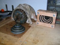
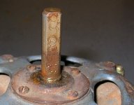
Worked tried the pulley again with the screwdriver, it won't budge
 I soaked the shaft & set screw hole area with PB Blaster now too. At most the entire rotor assembly/shaft moves with the force of the pry ~ 1-2mm. I don't want to force more. Unless I can get the shaft pinned down with something through the pulley hole so the shaft don't move.
 I'm beginning to wonder if a puller is worth trying to fab up. I don't have much clearance between the pulley and end cap screws, ~1/8" and a hair more. And the pulley is soft aluminum.
I'm also wondering if there's another way to skin this cat. Instead of pulling on the pulley, tap out the shaft. I realize the support for both still comes at the same point at the bottom of the small pulley, but
 I'm wonderng if motor disassembly is possible, to strip it down to the rotor assembly, the end cap and the pulley so that the load is easier to control or rig up. Ok, just thinking out loud. Not certain what else to do at this point. It needs more muscle and pounding, but there's not really anywhere to apply that too.
Attachments

xtremek
Well-known member
Two of the thickest pieces pieces of flat stock at the back of the pulley, the stock spanning a gap in a vise or other support with the motor in the middle of the span. Some warming of the pulley with a torch and then tapping on the motor shaft?
OP
GirlnAgarage
Well-known member
Thanks guys.
Going to try some torsional force on the pulley, see if I can break it loose. It was suggested over on the OWWM site that there may be set screw burs binding up the works. What I'll try is put the other end of the shaft in a padded vise and try to twist the pulley. I'll try a gloved hand first. If that doesn't work I'll try an oil filter wrench. If this method won't budge it I may move to the next plan, building a puller jig. As I joked there, building a tool will be the most elaborate part of this motor refresh.
Going to try some torsional force on the pulley, see if I can break it loose. It was suggested over on the OWWM site that there may be set screw burs binding up the works. What I'll try is put the other end of the shaft in a padded vise and try to twist the pulley. I'll try a gloved hand first. If that doesn't work I'll try an oil filter wrench. If this method won't budge it I may move to the next plan, building a puller jig. As I joked there, building a tool will be the most elaborate part of this motor refresh.
OP
GirlnAgarage
Well-known member
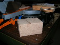
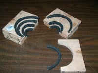
Tried turning the pulley on the shaft, didn't work. My patience ran out so I'm getting serious. All along I figured a puller would be necessary to get this pulley off. I had trouble reconciling applying the puller to the pulley without wrecking it. Slept on it and came up with this, a pulley shell. The idea is to spread the force of the pull throughout all the pulleys using a wooden collar on each pulley step. And pad the grooves to support the ears so they resist collapse. That's the idea anyway. I hope it works out that way.
Getting started...
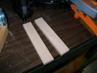
Bought some wood. Yep, oak. A $9, 36" piece of oak. It's all I could find in 1/2" thickness. That's how we roll in this house, oak for a scrap jig.
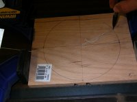
I need four collars. In order to put each one on they have to be in two pieces. So, I cut out my eight pieces (well six at first and realized I needed two more).
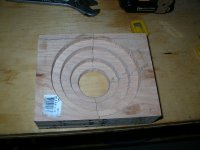
Mated two halves (consecutive cuts for flush fitment). Found my center point, marked my radius and drew out a circle with my fancy compass.
I don't have a scroll, jig or band saw so I had to cut a circle the poor man's way, with a drill. Zipped out a million 1/8" holes with the Dewalt. That thing lasted two hours on one battery, drilled out six pieces at a leisurely pace. Had to drop in a fresh battery to finish the last two pieces.
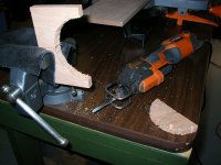
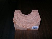
From there I used my Ridgid Fuego with a small bi-metal blade to cut out the perforations.
Because I have no drum sander or no drum sanding bit for the DP I had to use the Dremel. That actually worked quickly. I forgot how fluent I've gotten using it from my leatherwork.
Cont...
Getting started...
Bought some wood. Yep, oak. A $9, 36" piece of oak. It's all I could find in 1/2" thickness. That's how we roll in this house, oak for a scrap jig.
I need four collars. In order to put each one on they have to be in two pieces. So, I cut out my eight pieces (well six at first and realized I needed two more).
Mated two halves (consecutive cuts for flush fitment). Found my center point, marked my radius and drew out a circle with my fancy compass.
I don't have a scroll, jig or band saw so I had to cut a circle the poor man's way, with a drill. Zipped out a million 1/8" holes with the Dewalt. That thing lasted two hours on one battery, drilled out six pieces at a leisurely pace. Had to drop in a fresh battery to finish the last two pieces.
From there I used my Ridgid Fuego with a small bi-metal blade to cut out the perforations.
Because I have no drum sander or no drum sanding bit for the DP I had to use the Dremel. That actually worked quickly. I forgot how fluent I've gotten using it from my leatherwork.
Cont...
Attachments


OP
GirlnAgarage
Well-known member
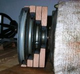
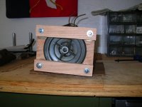
Next order of business was cut the old Cman belt. It is the spacer for the pulley grooves. These will be glued in to the wood collars. They are loose for now for mock up.
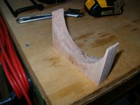
You can see a profile picture of what this will look like with only half the collars installed on the pulley. I need to run a small bevel around the top surface of the inner circle of each collar. The bottom of each pulley has a slight angle towards the center before it flattens out at the edges. The bevel will allow the collar to collapse perfectly flat instead of the corner sitting on the angle and being the main point of force.
I haven't worked through this yet but I think....
To finally apply the 2/3 jaw puller I will secure the collars together all in one block, likely a bolt or screw at all four corners. Not certain how I intend to hold the halves together. At this point I think I'm winging it for whatever grand idea hits. I'll use a strip of 1/8" x 4" long piece of angle iron to span the collar half edge. That will be my pulling point for the jaws.
Well, just needed to make some progress, even if for a psychological victory.
Attachments
Outlawmws
Well-known member
Girl, You are freaking AMAZING! If that doesn't work, I don't know what will! Great idea, and I'm sure one that will get repeated more than once! 
Re: Reorganization, it's like a renovation
Holy buckets!!!! That's freaking amazing! That's some ingenuity there!!! Great job!!
II'm gonna steal that and it will definitely be filed in my bag of tricks. Of course I'll give credit where credit is due if I ever have to use it!!!
Jeff
Sent from my iPhone using Tapatalk
Holy buckets!!!! That's freaking amazing! That's some ingenuity there!!! Great job!!
II'm gonna steal that and it will definitely be filed in my bag of tricks. Of course I'll give credit where credit is due if I ever have to use it!!!
Jeff
Sent from my iPhone using Tapatalk
OP
GirlnAgarage
Well-known member
Thanks yall. The jig is pretty extensive for such a simple task. Least it seemed that way to me. Along the way I stopped, looked around and laughed to myself at the power tools I had out. One tool for each step. Even the shop vac in between each piece. And to be a bit whimsical I marveled at the job each one had to do (my forearm was cramping a little bit, ahem, "the job I had to do"), just so I could cut out a semi-circle!
I hope it works. Don't have the jaw puller so I'll go get one today. Finish up that last bevel, double check the fit and glue the belts in place. I should be able to make a pull sometime today. Tonight I'll either be looking for parts or celebrating (It's the small stuff).
Gorilla, haven't tried heat (Don't stone me Bro!). With no way to pull on the pulley, applying heat didn't seem like it would do much good without a good way to move it. I didn't think prying on it or torsional force would be enough and heating would be a waste. Did I short change myself? Should I go back real quick and give it a quick shot in the vise again before proceeding? Guess it couldn't hurt if I can keep the shaft from spinning. At this point I kinda want to see if my jig works lol The only spot heat applicators I have around is a hair dryer, soldering iron and two welders. I think the hair dryer is the winner.
Along the way I stopped, looked around and laughed to myself at the power tools I had out. One tool for each step. Even the shop vac in between each piece. .
That's my problem. I think about all of the tools required just to do a task and I just give up and don't even start because I don't want to mess with putting everything away!!!!
Jeff
OP
GirlnAgarage
Well-known member
That's my problem. I think about all of the tools required just to do a task and I just give up and don't even start because I don't want to mess with putting everything away!!!!
Jeff
Haha Yeah this one was a real test. And it's why I hesitated going this route. Apparently my compulsion to beat the challenge is greater than the amount of work involved

I did take breaks as I went along to tidy up. Since I was drilling and cutting in the same spot, after each piece I would run the shopvac. I think I'd have gone nuts working that many pieces in a dirty space. Plus I was wearing flip flops and I had to keep the sawdust from falling and getting all in and annoying me. (I know I know, flip flops are not proper footwear for the garage/shop. I was going to wear my boots but then the sawdust falls in them when I wear them with my shorts. I know I know, shorts are not the proper attire for leg wear working in the garage/shop. But I was hot)
Well, if the jig doesn't work out, I'm happy I built it, at least right now I am. I got to "work on" something and it came out as I had planned. I goofed around taking pictures of shapes with the collars. I felt like a kid playing with wood blocks.
Perhaps if this doesn't work I shall mount it as wall art lol
Attachments


OP
GirlnAgarage
Well-known member
Oh, I think the hitch in my plan that I"m going to check out right now... For the puller I need the big 5T puller with the large 7" jaws. That will work perfectly to get around my jig. However the center drive bolt may be too large a diameter to fit in e center pulley hole. So, I have to find a work around if it is.
Or fab a puller of my own, which I admit I was just thinking about also to incorporate the method to hold the halves together...I got ideas! have to go. I smell blood in the water
Or fab a puller of my own, which I admit I was just thinking about also to incorporate the method to hold the halves together...I got ideas! have to go. I smell blood in the water
Outlawmws
Well-known member
Girl, just put a suitable socket that can reach the smaller diameter of the motor shaft in there, it should work fine.
I'm assuming you will use a C-clamp on the two wood shells to hold it together.
Heat: not too sure how much good the heat of a hair drier will do. the usual weapon of choice is either a Bernz-O-Matic torch, or a OA torch . have to be a bit careful as you down want to melt the aluminum, just heat it (without getting the motor shaft too involved...)
Outlawmws
Well-known member
Gorrilla, while 4 step pulleys are relatively common, these have a spacing not like the "common" fractional HP sheaves you see around. Commonly broken, so snapped up pretty quick when they come up on Eprey.
dsquire
Well-known member
Oh, I think the hitch in my plan that I"m going to check out right now... For the puller I need the big 5T puller with the large 7" jaws. That will work perfectly to get around my jig. However the center drive bolt may be too large a diameter to fit in e center pulley hole. So, I have to find a work around if it is.
Or fab a puller of my own, which I admit I was just thinking about also to incorporate the method to hold the halves together...I got ideas! have to go. I smell blood in the water
GirlnAgarage
One thing to be aware of is that sometimes they will put 2 set screws in the same hole to hold a pulley in place.
The first one holds it tight to the shaft. The second one keeps the first one from comeing loose. I learned that trick the hard way, many years ago.
Best of luck getting the pulley free.
Cheers

Don
OP
GirlnAgarage
Well-known member
Insert favorite victory rock anthem and turn. it. up! Get in the truck, we going out to celebrate! Woowooo!!
Oh, in case you haven't figured it out, the pulley is off. Safe and sound. I got a ton of photos and I am uploading everything start to finish from today. Happy Happy Happy.
Get in the truck, we going out to celebrate! Woowooo!!Oh, in case you haven't figured it out, the pulley is off. Safe and sound. I got a ton of photos and I am uploading everything start to finish from today. Happy Happy Happy.
Attachments
Last edited:
cbacres
Well-known member
See, if your had air horns, your could blast them on the way to celebrate.
Nice work.
Nice work.
OP
GirlnAgarage
Well-known member
See, if your had air horns, your could blast them on the way to celebrate.
Nice work.


Thanks!
Ok, getting started today wasn't exactly sure what my next steps were to complete the setup. I knew I had to bevel the edges to proceed. So I did that. Just used my Dremel and sanding drum. Quick work.
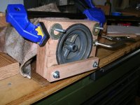
I mocked up the collars and secured them with a clamp to check fit. Liiiight bulb. Da le gas! (I say that because I have not glued the belt strips to the collars. I decided to skip that step as at this point it doesn't seem necessary)
Cut two strips of oak. Drilled holes. These will be my half connectors.
Drilled the corresponding holes in the collars. Ran 1/4" thread rod. Used a thick washer in between the strip & top collar to account for the gap created by the top pulley. Just to snug down evenly.
The unit is all bolted up and ready to attempt a pull.
Attachments


Outlawmws
Well-known member
I want a Utube vid of you doing your victory dance! 
Outlawmws
Well-known member
And there is Irony here: using one DP to fix another DP! See, you NEED 2 DP's!
OP
GirlnAgarage
Well-known member
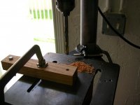
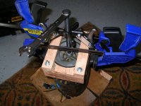
Set the motor up on the floor on the garage doormat. So in case I dropped it it didn't have far to fall.
I needed 13 hands to get the little angle iron pieces in place. They are my pull point that span the collar half gap on the bottom of the jig. These need to be in place. Finally figured out that if I use the scrap wood wedges to hand them up I could clamp the edge down. Left the middle area open for the puller jaws.
Getting the puller setup I needed 28 hands. I swear I was wrestling an octopus trying to get the set up secure. I used a second clamp to hold the jaws in place on the angle iron. I intended to prevent those suckers popping off under tension. Finally got it and started to turn the bolt with a 5/8" wrench. Not far into it I had to stop, back out and snug the arms into a position other than loose. I found the more I cranked the more the arms pulled inward, which was smashing the top strip and distorting it also leveraging the jaws off the angle iron. Once I got them set, it was easy.
I turned the wrench and got a little spooked. It turned easily and made no noise. I wondered what I broke lol Looked under and saw it was moving. Success!
I ran out of bolt. The bolt was just a hair big to fit into the pulley center hole. So I inserted a 1/4" deep 9mm socket (Cman if it matters). And it took it the rest of the way.
 I am so glad at this point. Decided I was doing nothing else in the garage other than breathing a sigh of relief, clean up and bask in the glory. I knew it would be that way. All that work just to accomplish one thing
I needed 13 hands to get the little angle iron pieces in place. They are my pull point that span the collar half gap on the bottom of the jig. These need to be in place. Finally figured out that if I use the scrap wood wedges to hand them up I could clamp the edge down. Left the middle area open for the puller jaws.
Getting the puller setup I needed 28 hands. I swear I was wrestling an octopus trying to get the set up secure. I used a second clamp to hold the jaws in place on the angle iron. I intended to prevent those suckers popping off under tension. Finally got it and started to turn the bolt with a 5/8" wrench. Not far into it I had to stop, back out and snug the arms into a position other than loose. I found the more I cranked the more the arms pulled inward, which was smashing the top strip and distorting it also leveraging the jaws off the angle iron. Once I got them set, it was easy.
I turned the wrench and got a little spooked. It turned easily and made no noise. I wondered what I broke lol Looked under and saw it was moving. Success!
I ran out of bolt. The bolt was just a hair big to fit into the pulley center hole. So I inserted a 1/4" deep 9mm socket (Cman if it matters). And it took it the rest of the way.
I am so glad at this point. Decided I was doing nothing else in the garage other than breathing a sigh of relief, clean up and bask in the glory. I knew it would be that way. All that work just to accomplish one thing Attachments


OP
GirlnAgarage
Well-known member
I want a Utube vid of you doing your victory dance!
High fives (the air with my imaginary friends), hootin', hollering, roughing up the dog, and least but not least taunting the pulley...athlete style victory celebration
And there is Irony here: using one DP to fix another DP! See, you NEED 2 DP's!
Perfect!
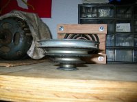
I shall tell him tonight Here's the after photos when I got the motor and pulley back on the bench. There was no metal burrs or scratch marks. Looks to me that the shaft under the last 1/4"-1/2" under the pulley just rusted and stuck. There are a number of set screw marks. So either someone used the multispeed pulley a lot (enough to keep adjusting the heights that are called for in the diagram) or they just kept moving it around for who knows why.
The pulley came out great. I don't see any distortion or cracks. There's not even any pressure marks from the wood or belt.
One thing on the shaft, I didn't notice it then but looking at the photos now, it looks like the shaft is slightly crooked. I need to go in there and have a better look. But for now. I'll just clean it up as I go through the motor rebuild.
Attachments


Wingnut65
Well-known member
Awesome and Ingenious work Girl! Very impressive!
I'm sure it was frustrating in the process, but also enjoyable to be using your tools in your own shop! Nice work!
I'm sure it was frustrating in the process, but also enjoyable to be using your tools in your own shop! Nice work!
OP
GirlnAgarage
Well-known member
Gorrilla, while 4 step pulleys are relatively common, these have a spacing not like the "common" fractional HP sheaves you see around. Commonly broken, so snapped up pretty quick when they come up on Eprey.
This is true. In the last few days as I built the jig and considered the options for pulley removal, I also searched the usual options to find a used pulley, with no success. These parts aren't common. Best option is another machine/tool head who has a spare from a tear down or parts machine.
Several suggestions in my search for help talked about the possibility of sacrificing either the motor/rotor or the pulley. I didn't like that kind of talk because of parts availability and losing more original parts.
My motor is a 115.6962. It's a 1/2HP with the tag stamp "H4 48".
GirlnAgarage
One thing to be aware of is that sometimes they will put 2 set screws in the same hole to hold a pulley in place.
The first one holds it tight to the shaft. The second one keeps the first one from comeing loose. I learned that trick the hard way, many years ago.
Best of luck getting the pulley free.
Cheers
Don
Thanks Don. Yep, checked for a second set screw just in case but this was a single. Turned out to be rust and pitting that grabbed the bottom end of the pulley to the shaft.
Awesome and Ingenious work Girl! Very impressive!
I'm sure it was frustrating in the process, but also enjoyable to be using your tools in your own shop! Nice work!
Thanks Wingnut. You are right that it was enjoyable to use my tools. I had a moment of clarity as I set up the DP to drill the strips. I had pulled out and used a lot of my tools all at once. When was the last time I did that?? As much as I wanted to get through to the pulley it was also a chance to stop and smell the roses. Made the success of the project that much sweeter
OP
GirlnAgarage
Well-known member
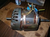
In regards to the motor wiring (115v), what gauge wires should I use to replace the worn out wires? 14ga? 16ga? Also I'll use a new 3wire power cord, any particular size suggested?
Also a far out question, would it be a problem to smear a little Anti-seize on the pulley shaft before I reinstall the pulley so we don't have a repeat stuck pulley episode? (I remember a compatibility question with electrical things).
ETA: random question, why does this motor have a shaft at both ends?
Last edited:
Outlawmws
Well-known member
Girl, you are talking the internal wires from the junctions to the windings? I'd match the current ga. (take a scrap with you to the Hdwr store, if you don't have a wire gage.)
For the cord, sort of amps/volts dependent, as well as run length, but I'd match or upgrade, but also not less than 14 ga IMO (assuming a 6 ft cord)
Anti seize would be a good idea (It's all about dissimilar metals...), as would a second set screw we have mentioned before if there is room/treads (also anti-seize).
Double shafts were common on non-reversible motors for a "mechanical" reverse (swap ends) also for mounting an arbor on each end for buffers, and wire wheels. some were used on multiple tools instead of being a dedicated motor. so this also added flexibility, and heck one end could drive a tool the other could mount a sanding disk or arbor for whatever.
OP
GirlnAgarage
Well-known member
Girl, you are talking the internal wires from the junctions to the windings? I'd match the current ga. (take a scrap with you to the Hdwr store, if you don't have a wire gage.)
A wire I know is broken (the rubber sheath is cracked off almost completely), for example, the black wire from On/Off switch to the power cord. That's one I'll have to replace. I am anticipating any other internal wires to/from the centrifugal switch, the OverLoad Switch, etc since I am separating the O/L end cap and stretching those wires which might induce cracking (hard to see sine there is a weaved cloth sheath over them).
Interesting note, the conductor wire for that switch-to-power cord is silver in color. That would make it aluminum, right? Obviously I'm going to pick up copper stranded but just thought it was neat to see the old wiring.
For the cord, sort of amps/volts dependent, as well as run length, but I'd match or upgrade, but also not less than 14 ga IMO (assuming a 6 ft cord)
I plan to go with a 6' power cord, 115v motor spec. The breaker for this garage circuit is a 15amp GFCI.
Anti seize would be a good idea (It's all about dissimilar metals...), as would a second set screw we have mentioned before if there is room/treads (also anti-seize).
Good deal. I have Antiseize and will see about a second set screw.
Double shafts were common on non-reversible motors for a "mechanical" reverse (swap ends) also for mounting an arbor on each end for buffers, and wire wheels. some were used on multiple tools instead of being a dedicated motor. so this also added flexibility, and heck one end could drive a tool the other could mount a sanding disk or arbor for whatever.
I see. So these are pretty handy little motors.
Thanks for the quick reply. Running out for an errand so I can get the small stuff while I'm out.
Outlawmws
Well-known member
Girl, the silver one is probably tinned copper. Unlikely that they would use aluminum in the 50's. inside a motor. They did start using aluminium in some house in the 60's IIR correctly.
OP
GirlnAgarage
Well-known member
Well I learn something new every day. Thanks Outlaw
ETA: looked it up http://www.arcorelectronics.com/resources/why-use-tinned-copper-wire/
Interesting.
ETA: looked it up http://www.arcorelectronics.com/resources/why-use-tinned-copper-wire/
Interesting.
Last edited:
OP
GirlnAgarage
Well-known member
Thanks Nine4. Gotta handle these classic old things with care. Sorry to hear about the hammer that got to your pulley.
I keep picturing your motor rebuild photos as I dig into this. You seem pretty fearless on this electrical stuff. I'm a nervous wreck. Need to get this finished up so I can get some sleep at night (my brain doesn't turn off when in the middle of a vexing project)
I keep picturing your motor rebuild photos as I dig into this. You seem pretty fearless on this electrical stuff. I'm a nervous wreck. Need to get this finished up so I can get some sleep at night (my brain doesn't turn off when in the middle of a vexing project)
cbacres
Well-known member
Don't know if your planning on a replacement cord with a molded plug, when I replaced the cord on my Powermatic, I used a SO type cord and a nylon cord cap (plug). I wanted a longer cord so I used a 12gage wire. A little overkill, but is is longer.
I like the nylon as its tough and won't crack if dropped.
Don't forget a strain relief/cord grip where it enters the motor.
I like the nylon as its tough and won't crack if dropped.
Don't forget a strain relief/cord grip where it enters the motor.
truckin23
Banned
Just finish reading from the beginning subscribing awesome
OP
GirlnAgarage
Well-known member
cbacres
Well-known member
I'd say you are. Serious iron and copper in that motor.
OP
GirlnAgarage
Well-known member
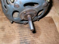
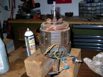
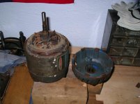
Overview of Craftsman 1/2hp motor 115.6962 disassembly
Once the pulley was out of the way I pulled the end cap using the gear puller. It did not take much effort at all. I hand tightened the puller bolt and it walked the bearing off the shaft.
Next I gently pried the metal body ring from the O/L end cap. Used some PB Blaster to lube the rust and a flat head all the way around, little by little. Careful not to crease or bend the metal with the flat head.
In pics 3 & 4 the motor waffled back and forth in these two positions for the longest time. Anyone who has disassembled one of these knows exactly the step I am on. It is the one where you try to reach the terminal bar screws with a really long screw driver. My really long screwdriver is broken (someone used it to pry something long ago) I tried to grind a flat point back on it, instead I made a shiv. Lots of frustration in this step.
Picture 5, I committed to snipping the three wires from the motor. I a in there anyway and will be replacing wires - why not? Pulled my electrical tool box off the shelf, pulled the cutters and was reaching for the wires when the solution struck.
Remove the wires from the terminal bar connection via the easily reachable nuts.
Attachments


OP
GirlnAgarage
Well-known member
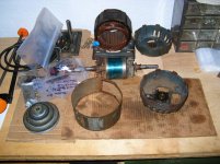
Once the wires were off the terminal bar bolts, the rotor assembly and O/L end cap came right off. I set aside the coil.
Propped up the rotor & cap and removed the centrifugal switch screws.
Flipped over and setup the rotor & cap. Installed the 3jaw puller. I needed a helper to hold the jaws while it tensioned. This end took more force. It lightly popped upon release. From there it pressed out fine.
Rotor assembly out and O/L end cap disassembled of the small pieces.
Here's my electrical map and notes. Every step, every part was written down here. If I didn't do a good job with my notes, reassembly ought to be real fun.
Attachments


OP
GirlnAgarage
Well-known member
Don't know if your planning on a replacement cord with a molded plug, when I replaced the cord on my Powermatic, I used a SO type cord and a nylon cord cap (plug). I wanted a longer cord so I used a 12gage wire. A little overkill, but is is longer.
I like the nylon as its tough and won't crack if dropped.
Don't forget a strain relief/cord grip where it enters the motor.
I am planning on a replacement cord. Not sure which direction - a prebuild power cord or making my own. Since I've got this machine inside I am leaning towards the standard 6' cord w/molded on plug.
Just finish reading from the beginning subscribing awesome
Thanks
I'd say you are. Serious iron and copper in that motor.
There sure is. I ought to weight parts out of curiosity.
- Status
- Not open for further replies.