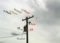
Interex
Well-known member
It's 208v in my building.

Learn something new every day ! I thought all "rotary phase converters" were built on the motor-generator principle !!Rotary phase converters do use the two legs of the SINGLE phase as two legs of the three phase when a rotary converter is constructed.
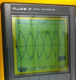
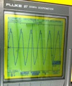
Let me appologize for the next 2 pictures. I do not have the software or cable to transfer screen captures from my Fluke 97 to a computer. I took these with my iPhone.
This picture shows channel A connected to L1. Channel B is connected to L2. You can see what appear to be two phases, 180 degrees apart.
As far as the 120 loads are concerned, each device only sees a 120 volt (RMS) sine wave. They don't care if they are connected to L1 or L2.

Appearances can be deceiving.
You posted too soon.
") Seriously, good pics. But it still won't convince some people.
Seriously, good pics. But it still won't convince some people. We can have a lot of fun playing on words......
The reality is....it's single phase....give me a transformer with an adjustable center tap and I can move the reference anywhere you want.
The key fact that shows that it's single phase is how you hook it up....both wires can go to a single transformer winding....if it was 2 phase, you would have to have two seperate transformers.
For example, I will sometimes use a 3-phase control xformer (480 to 120). I have to use a 3phase load center....which means I end up with 3 120Vac feeds....they all have the same neutral....but each phase is 120 hz out of phase with the adjacent phase. If I go and measure from the hot of one phase to the other, am I going to get 240/241? NO....I will get 208 Vac RMS (using a Fluke meter).
But in a single phase 120/240 system....if I measure from one hot to the other....I get 240/241 (what ever it takes)
I think you guys in the field are making this confusing on purpose, to keep ignorant people like me from ever learning your craft. A job security measure, I suppose.
Because, after reading this whole damn thread, I still don't know what to believe.

Bull,
There is no disputing what it is. This is not job security to obfuscate and make it incomprehensible for some. This is just plain factual. There really is only one person who continued to dispute what are plainly, and simply put, the correct interpretation. Many, many engineers and sparkies have chimed in one after the other and said that it is single phase. You can believe them. Or you can do your own homework and Google most of what they have said and find that it is true. Go to the Mike Holt electrical forum and search around. The NEC is very clear. The answer is very clear.
There's one item, research, that I see the younger generation being unable or unwilling to do -- on many topics and maybe it is only age and wisdom that turns that around -- I'm just not sure.
Cheers,
And good job to all those who continued to add on with their own information, diagrams, pictures, etc.
JimDon
Bull,
I did my graduate work in an institution in Milwaukee 37 years ago, so you can pretty much do the math. My remark about younger folks was really not aimed at you in particular, but many of the "younger" generation that I see today -- my two college graduate youngsters included. They want easy, simple fast answers with not a lot of thought put into it and not a lot of gray outside the "clearly" defined black and white borders that they see. Didn't mean to step on toes, just a bit of frustration peaking out around the edges as to what I see an an overall problem today.
Cheers,
Jim
If you google "rotary phase converters", most everyone states "single phase to three phase conversion".
Rotary phase converters do use the two legs of the SINGLE phase as two legs of the three phase when a rotary converter is constructed. But look at the waveforms - The 1st picture (lifted from another website) shows a full 3 phase waveform. The second shows the output of a rotary converter.
The two "phases" made from the single phase input is no where near 120 degrees. The 180 degree input is "pulled toward a 120 degree shift, but never makes a true 120 deg shift. This is the cause of the "wild leg", usually much higher in voltage than the other two.
Uh, yeah, that is why run capacitors are used to balance a rotary phase converter.
While you may get differing phase to neutral voltages from the three phases out of a single phase to 3 phase converter, the imperfect pulling of the phases is not the reason for a wild leg.Alchymist said:The two "phases" made from the single phase input is no where near 120 degrees. The 180 degree input is "pulled toward a 120 degree shift, but never makes a true 120 deg shift. This is the cause of the "wild leg", usually much higher in voltage than the other two.
Reminds me of a lab we did in one of my EE classes. We had to determine the length of coax by injecting a pulse at one end and then observing the reflection and the same end. Interesting especially when you change the terminator (or lack there of).Get me enough cable and I will make 3 phase from single phase.
Yep. I was very concerned after I ordered some computer equipment that was listed as 220V when I found out that only 208V was available in the building. Worse the corporate electricians install the wrong receptacle instead of the NEMA 6-20R that was requested.You can still call it 220 but remember that 220 volts versus three phase 208 volts remains a non-trivial difference and equipment meant for one cannot be used on the other unless intended for such usage perhgaps as evidenced by labeling.
Reminds me of a lab we did in one of my EE classes. We had to determine the length of coax by injecting a pulse at one end and then observing the reflection and the same end. Interesting especially when you change the terminator (or lack there of).
You can still call it 220 but remember that 220 volts versus three phase 208 volts remains a non-trivial difference and equipment meant for one cannot be used on the other unless intended for such usage perhgaps as evidenced by labeling.
While you may get differing phase to neutral voltages from the three phases out of a single phase to 3 phase converter, the imperfect pulling of the phases is not the reason for a wild leg.
The wild leg situation exists because, when the neutral is assigned to the center tap of one of the three transformers in a 3 phase delta arrangement, the phase to neutral voltage of the third leg (the leg not on the center tapped transformer) is 1.73 times the phase to neutral voltage for the other two legs. For a phase converter, any pulling away from 0 or 180 degrees to get a third leg will either result in a lower phase to phase voltage and/or result in a higher phase to neutral voltage for the third leg compared with the other two.
We were only given a 'scope so it was a bit "more challenging" !It's called TDR- Time Domain Reflectometry. There are oscilloscope like instruments for this.
Using one of these, one can pinpoint an open or short or even a mechanical problem in a cable - and tell exactly where in the cable it occurs.


 !
!It will work in theory - they are called inductors. You can cut down on the cable length by coiling the cable, and reduce it even more by using an iron core. You should see what a 1 inch length of wire does at 10 Ghz!